


Question 58: What issues are experienced at the desalter and pre-heat train when recirculating brine at the desalter?
SHENKLE (Flint Hills Resources, Ltd.)
Before answering this question, I want to clarify that the panel has defined ‘recirculating brine’ as brine going back to the freshwater makeup. For example, it may be used when insufficient makeup is available to maintain recommended washwater rates. We do not recirculate brine. We inject makeup water upstream of the second stage mix valve. Second-stage brine is pumped back to the first stage upstream of the mix valve, and then the first-stage brine is effluent. We operate washwater rates that are typically in the range of 4 to 5%.
SLOLEY (CH2M Hill)
Brine can be recirculated at the desalter. Additionally, there are some plants that recirculate brine found upstream in the heat train network. This is used in plants that have insufficient water to get proper contacting across the mix filter and which are often trying, in extreme cases, to move even from 2 or 3% water up to around 4 or 5% water. Since the freshwater rate does not increase when you do this operation, if it is more effective, you will increase the solid content of the brine. After all, that is the objective.
In some units, problems can arise due to oil and water emulsification because the pump that needs to recirculate this water – if you have oil in it – is a great mixing device. If the brine does not effectively de-oil, this water will recirculate and could cause problems with the rag layer in the desalter. Additionally, if the soap content of the water is high, you will get emulsions forming. With higher total water rates in many of these desalters also, the total water residence time is reduced, making the oil and water emulsions more difficult. The downstream exchange of equipment fouling and corrosion rate should be lower. If it is not changed or gotten worse, you should stop the brine recirculation.
HODGES (Athlon Solutions)
We are huge fans of recycling brine. In most cases, it is the Best Practice to increase the effectiveness of your desalter by increasing the effective washwater percentage through brine recycle, which will drive optimum desalting. As I mentioned earlier, one of the key items that is often overlooked when doing this is your seal flush. Make sure that you do not use the recycled water for your seal flush because it will erode your seal. Use fresh water. This may be subtle to some and obvious to others. Make sure that when you are recycling, you are not replacing your fresh water with recirculated brine. Recirculating brine is only used to add more effective percentage washwater. If you back out the freshwater, you will be taking a step back in effective desalting and contaminant removal across the desalter.
TOM COLLINS (Forum Energy Technologies)
Recirculating effluent water back to the desalter can improve efficiency by increasing water droplet population, allowing for larger droplets and faster settling. When recycle water is used, it is typically injected just before the mixing valve, not into the pre-heat train. It is also recommended that you divert the recycle when mud-washing unless a continuous mud-wash is used. Additional water volume may also allow for improved mixing efficiency, due to an increase in the water droplets created in the mixing valve or emulsification device. Care should be taken not to recycle water high in oily solids or other emulsifiers that may help stabilize interface emulsions and increase BS&W.
GLENN SCATTERGOOD (Nalco Champion Energy Services)
It is important to recognize the benefits of desalter washwater recycle, which improves dehydration and leads to improved salt removal. A higher rate of desalter washwater may also increase solids removal when processing high solids crudes.
DENNIS HAYNES (Nalco Champion Energy Services)
Recirculation of brine is a very good strategy to increase washwater to the desalter while minimizing effluent flow to wastewater treatment. The issues that may be experienced during this recirculating brine include a potential reduction in solids removal due to sending desalter effluent containing some solids through a pump motivating the flow back to the combined washwater inlet. More so, an issue is that if there is any upset or degree of oil in the effluent, the shearing action of the recycle pump will tighten the effluent emulsion. This emulsion, combined with the washwater into the raw crude oil which is then emulsified via the mix valve, may create interface growth in the desalter to the point that the system upsets. The brine recycle should be used with a non-oily effluent.
PHILIP THORNTHWAITE (Nalco Champion Energy Services)
It should be remembered that if a desalter operation is washwater-limited, the use of a brine recycle is an effective means of increasing the washwater volume and improving both dehydration and desalting performance. However, the operation is not without risk, and there are operation considerations to be made.
First, the recirculation of effluent brine is, in effect, adding salt to the crude oil when the two are mixed together. As a consequence of this combination, if the salinity of the brine significantly increases, the mixture can limit the salt removal efficiency across the desalters, the optimum salt content of the desalted crude increases, and the process efficiency can actually decrease. This reaction can be mitigated to an extent since the increased washwater volume leads to improved dehydration and desalting efficiency. Additionally, any increase in overhead chlorides can be mitigated to a degree through good monitoring and caustic management practices.
The other major consideration is that any deterioration in the effluent quality can have a significant impact on the whole desalter operation. If there is an upset leading to an oil undercarry, the oily brine will be passed through the brine recycle pump leading to the formation of a very stable emulsion. As this stable emulsion forms part of the total washwater feed, it can lead to emulsion layer growth within the desalter vessel and begin to exacerbate the already upset conditions. Key to mitigating this threat is regular visual checks of the try lines and effluent quality so that any onset in effluent deterioration can be quickly acted upon.
Year
2013
Process
Question 14: What is industry experience of using tri-metal (platinum-rhenium with promoter) catalysts?
MELDRUM (Phillips 66)
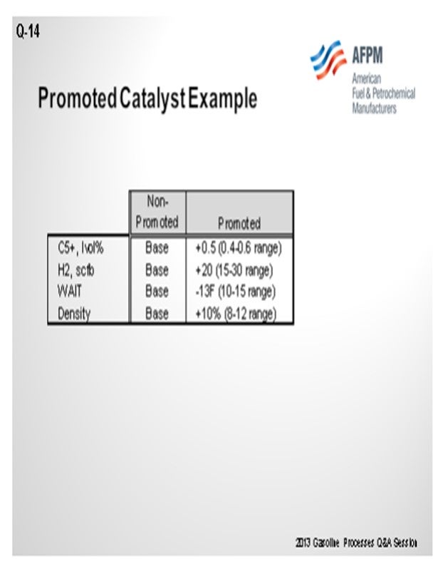
Promoted or multi-metallic reformer catalysts have been a topic of research since at least the early 1970s. They have been tried commercially in various forms over the years, all with the objective of improving yields by suppressing the demetallization reactions. The current promoted catalysts have advanced the formulation of manufacturing techniques to new levels of performance. Recently, Phillips 66 has selected promoted catalysts for future reloads in at least three of our sites. The additional cost of the catalyst is justified when considering increased product yield and improved activity that allows a lower reactor temperature requirement, which both provide for a very quick payback on the additional catalyst cost.
The example shown on the slide indicates the additional yields – both in the C5+, as well as hydrogen – and some improved activity that might be expected with a promoted catalyst. When selecting the promoted catalyst, regeneration procedures should be reviewed with the catalyst vendor to ensure that maximum catalyst performance from regeneration to regeneration is achieved, particularly in the area of reduction and dryout steps.
BULLEN (UOP LLC, A Honeywell Company)
We have two catalysts that we offer in the semi-regenerator market and also for cyclic reforming applications. One of them is the R-98 catalyst that was introduced in 2005 and which has over 50 installed applications. We have a new catalyst called R500 that has better activity and stability, and we have put it in 10 units. As Craig said, proper regeneration procedures are very important for any semi-regeneration unit, and maybe even more so for these tri-metallic systems, because of the issues related to dryout and reduction. It is important to get consistency with this procedure because you will lose the advantage of the tri-metallic system if you do not do the dryout and reduction correctly. Getting that repeatability is very important.
CRAIG MELDRUM (Phillips 66)
Regeneration procedures should be reviewed with the catalyst vendor to ensure maximum catalyst performance from regeneration to regeneration. For example, UOP R-72 was a promoted catalyst offered about 15 years ago and required a different reduction procedure than the non-promoted catalyst for hydrogen concentration, pressure, temperature, and dry-down schedule.
PATRICK BULLEN (UOP LLC, A Honeywell Company)
Trimetallic catalysts containing rhenium are typical for use in fixed-bed reforming applications, both semi-regenerative and cyclic reforming applications. In recent years, both additional metals and oxides have been added to platinum-rhenium reforming catalysts. Metal promoters have been added to increase selectivity and product yields. The additional metal partially suppresses platinum-rhenium activity, reducing metal-catalyzed hydrogenolysis that lowers selectivity.
Over the past decade, UOP successfully developed the proper catalyst base, formulations (including promoter type), and manufacturing techniques needed to generate catalysts that demonstrate excellent yield stability and regenerability. UOP’s R-98 catalyst was introduced in 2005 and has over 50 successful applications with many regeneration cycles, and our customers are benefiting from the higher yields. UOP recently introduced a new product, R-500, that shows even great activity and stability, with over 10 commercial applications. It is well suited for reforming units where even longer cycle lengths are desirable or where higher activity is needed to push more barrels. The gradual acceptance of promoted catalysts is analogous to that of the bimetallic catalysts having higher rhenium content that preceded them in this market.
Proper regeneration procedures are critical for the success of any semi-regeneration catalyst; and in particular, promoted formulations that have reduced metal activity. One Best Practice is to ensure proper dry-down, reduction, and sulfiding. Cyclic reforming applications are a little more demanding due to the regeneration environment (higher moisture and sulfur, for example), but new promoted formulations have been demonstrated in these applications as well.
SONI OYEKAN (Prafis Energy Solutions)
This question needs some more definition to elicit appropriate responses with respect to what is truly a “trimetallic” catalyst. My initial response is that my experiences in the use of “trimetallic” platinum-rhenium catalysts for fixed-bed cyclic regeneration reformer operations were good. The catalysts performed as projected by the catalyst and technology supplier for catalysts containing a third metal that was specifically added for modifying the acidic functionality of the catalysts.
Having written that, it is important to understand the type of catalysts commonly referred to as “trimetallic” catalysts. The term could cover Pt/Re (platinum/rhenium) catalysts with a third metal as a modifier for the alumina to moderate the acidic functionality of the catalysts or those in which the third metals are added to modify the hydrogenation functionality of the platinum or to moderate rhenium hydrocracking activity. In other trimetallic catalyst formulations, the third metal can work in conjunction with the rhenium as co-promoters for the platinum functionality.
The performance objective of the third metal is crucial in order to assess long-term performance and benefits of the third metal. Metals on catalytic reformer catalysts typically undergo varying degrees of reduction to different oxidation states at different temperatures and adequate metals redispersion are achieved at different oxidative conditions. Trimetallic catalysts’ expected performances and potential limitations should be well understood by oil refiners before acquiring them for use. Catalyst suppliers should provide test data to show multiple regenerations and adequate reactivations of the three metals, even if the other two metals are acting as co-promoters for the platinum. Another key factor is to ensure that optimal metals distributions are achieved during catalyst manufacture. There are other factors to consider that are beyond inclusion in this short response on trimetallic catalysts.
If the third metal has been added to moderate catalyst acidic functionality and reactivation of that third metal is not an important factor other than decoking, then the refiners’ challenges are lessened to some extent. It should be recalled, however, that the history of catalytic reforming is dotted with an oil refiner’s experiences with second metals that had been added to the platinum and which led to significant performance problems. The problems were related to inadequate metals activation, especially poor redispersion of the promoter metals, and these problems led to poor catalyst performance for subsequent cycles after the first cycle for fixed-bed catalytic reforming systems. Furthermore, in reforming catalyst development programs, the addition of metals to Pt/Re catalysts led to increased feed sulfur sensitivity challenges for the resultant trimetallic catalysts. Feed sulfur sensitivity and catalyst regeneration challenges should be studied sufficiently by the catalyst and technology supplier during that supplier’s catalyst development studies leading to the production of “trimetallic” catalysts.
Year
2013
Process
Question 35: When processing tight oil crudes, are lower bed pressure drop problems in VGO/resid hydrotreater reactors a concern? If so, what mechanisms explain this issue?
LIOLIOS (DuPont Clean Technologies)
The highly paraffinic nature of the tight crudes and the destabilization of asphaltene molecules can cause precipitation and agglomeration. One of our customers with a gas oil mild hydrocracker switched feedstock to increase amounts of black wax crude. This was a five-reactor system. A guard bed reactor was first, followed by four other reactor beds. In the polishing reactor bed, this customer saw an increase in pressure drop. It was theorized that this pressure drop was caused by asphaltene precipitation and polymerization in the bed.

The following graphs show some of what was happening at this unit. It is a constant feedstock. They raised the temperature to get some additional cracking. You will notice an elevated pressure drop in the last bed shortly after they increased the severity of the unit. If you look at the next chart, you can see where they decreased the severity of operation of the unit and the pressure drop recovered. Our theory is that there was a recombination of those asphaltenes.

SHARPE (Flint Hills Resources, LP)
We have had no second and third bed ∆T problems when running high rates of Eagle Ford crude. When there were high bed ∆Ps in the lower treating beds, they were usually a result of coke fouling due to hydrogen starvation, and low hydrogen partial pressure.
GLENN LIOLIOS (DuPont Clean Technologies)
The highly paraffinic nature of tight oil crudes, and the potential increase in asphaltene precipitation when these crudes or cuts of these are mixed with polar asphaltenic oils or cuts, has been well documented. The increase in paraffin content can lead to destabilization of the asphaltene core which can then agglomerate to form larger macromolecules that may precipitate out under hydrotreating conditions.
A number of published documents2 detail the causes and reactions behind this phenomenon and outline methods to determine which crude type and cuts are compatible and what ratios are required to minimize the chance of this phenomenon occurring.
Much of the industry experience indicates that asphaltene precipitation and fouling in process units normally occurs in regions of high heat flux when agglomerated asphaltenes easily crack or dehydrogenate leaving coke-like deposits such as feed/effluent exchangers or where hydrotreater reactions are initiated; i.e., the top bed of a hydrotreating reactor. However, it was observed that a gas oil mild hydrocracking unit experienced a noticeable increase in pressure in a final polishing reactor after the feed to the unit was switched to process a feed that had been mixed with an increased percentage of highly paraffinic (black wax crude) feedstock. At the same time, the severity was increased by lowering the throughput without reducing inlet temperatures. The polishing reactor was the last in a series of five reactor beds, the bed being a separate bed reactor. During the observed increased pressure drop in the polishing reactor, no appreciable pressure drop was observed in the guard bed or main reactor beds. It is important to point out that after the space velocity and feedstock to the system were normalized, the pressure drop decreased almost to the baseline range prior to the event.
It is theorized that the observed bed pressure drop increase in the last bed was a result of asphaltene precipitation and polymerization on the bed that occurred after increased severity reactions cracked the smaller molecules that kept the increased asphaltenes in solution. According to work conducted by Wiehe on asphaltene precipitation3 , asphaltenes are maintained in solution in oil by a micelle type of configuration. This theory has been also explained by other authors4 . The asphaltene core is surrounded by a solvated shell that consists of resins. Resins are molecules with aromatic and naphthenic rings.
Under high severity conditions such as those experienced in this mild hydrocracker operation, the resins can crack into smaller molecules. This can disrupt the micelle type configurations at which asphaltenes are kept in solution, and the asphaltenes can precipitate upon cooling.
Analytical tests carried out on the hydrocarbon feed samples indicated that the asphaltene content (heptane insolubles), although low in comparison with a heavy residue5, was found to be approximately three times higher than the one on the sweet GO FCC feed sample that was being recirculated to the unit and the regular GO sample fed to the GHC.
This theory explains why the upstream reactor beds did not experience a corresponding increase in pressure drop. If it were due to deposits, catalyst fines, or simply rust from upstream units, the first two reactors should have acted as filters preventing the last bed from getting plugged-up.
JUAN ESTRADA (Criterion Catalysts & Technologies)
Two primary mechanisms for pressure drop in bottom beds are coking and asphaltene precipitation. Coking results from operation at elevated temperatures and hydrogen deficiency. Asphaltene precipitation results from a reduction in liquid solvency. The design of VGO hydrotreaters with elevated pressure, low space velocity, and high treat gas rates helps minimize coking; however, elevated saturation of aromatics reduces the solvency of the oil, increasing the potential for asphaltene precipitation in the catalyst bed.
Processing tight oils in the crude diet reduces the aromatic content of the gas oils. For this reason, the coking potential of the feed is lowered, but the potential for asphaltene precipitation increases. With lower feed aromatics and severe hydrotreatment, the solvency change may be sufficient in the lower catalyst beds to precipitate asphaltenes introduced with the other gas oil components from conventional or synthetic-derived crude sources.
The mechanism of asphaltene precipitation from a reduction in liquid solvency has been connected to many historical pressure drop problems involving changes in operation and feedstock qualities such as aromatic and C7/C9 asphaltene contents and the distillation tail. Applying this accepted mechanism to lower bed pressure drop problems in units processing tight oil derived gas oils logically explains recent pressure drop problems in a few VGO hydrotreaters. Refiners continue to learn compatibility limitations of co-processing tight oils in the crude diet, including impacts on VGO reactor pressure drop growth has become a consideration.
Year
2013
Process
Question 16: What is the typical carbon monoxide (CO) concentration in the reformer net gas? How is the CO content measured? What are the potential effects to downstream units from the CO?
MELDRUM (Phillips 66)
Carbon monoxide can form in reformer units as the hydrocarbon reacts with moisture under very low-unit pressure conditions. Typically, semi-regeneration reformer net gas would have nil CO and only a minimal amount in a CCR-type unit. I expect it to probably be on the order of 5 ppm (parts per million), though some units report routine measurements of 10 to 20 ppm CO in their net hydrogen off gas.
One of our cyclic units that was operating at 400-pound had CO as high as 20 ppm in its net hydrogen stream when the recycled moisture rose to around 300 ppm. The excessive water entered the reformer from a leaking side reboiler on a wet debutanizer that used a slipstream of the reformer reactor effluent as the heat source. The water then returned to the reformer product separator. The high CO caused deactivation in the catalyst in a downstream isomerization unit.
Accurate measurements of CO in the net gas are difficult. Reformer units are not expected to have much CO, so they seldom have an online analyzer. A colorimetric tube – Gastec or Dräger type – can be used to give an indication of the presence of CO, but accuracy for a quantified number is difficult and requires the use of a carbon pre-tube to remove the hydrocarbons.
CO is detrimental to downstream hydrogen-using units in three principal areas. CO in hydrogen being fed to a distillate hydrotreater will methanate, consuming the hydrogen that would have otherwise been used for the desulfurization reactions. This will have the effect of lower catalyst activity. CO in hydrogen fed as a makeup stream to an isomerization unit will also methanate and form moisture that will deactivate the isomerization catalyst. CO that did not methanate in the second example could act as a poison to the platinum metal function of the isomerization catalyst. UOP suggests a CO limit of 1 ppm max for isomerization hydrogen makeup gas. My Answer Book response also includes some of the common steps used to minimize CO formation in reformer units, particularly in a CCR unit.
BULLEN (UOP LLC, A Honeywell Company)
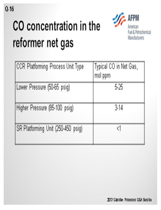
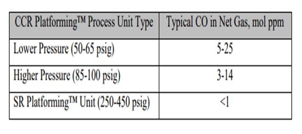
As you can see in this table, we have correlated some different types of operation and ranges of CO levels. As Craig alluded, the numbers vary quite a bit, which can be due to conditions in the unit, as well as analytical capabilities. There seems to be a trend that the lower pressure units generate more CO than higher pressure units.
The laboratory method we recommend using is UOP 603, which is a laboratory method for CO and CO2 and hydrogen. However, a lot of refiners cannot do this method. The gas detection tube route is fairly common. Our point of view is that with the gas detection tubes, if one carbon pre-tube is good, then two is better. So, we usually ask them to use two tubes instead of one to help eliminate the breakthrough of hydrocarbons that can make a false high value for CO.
As Craig said, the issue with chloride and alumina isomerization catalyst is that you will deactivate the catalyst. However, if you are using another type of catalyst, like the Par-Isom catalyst or zeolitic catalyst, the actual suppression you will get will be very dependent on what temperatures you are running. As you approach the 400°F temperature, you tend to methanize the CO in the first part of the bed. So CO tends to have less of an effect on the metal function of the isomerization catalyst and becomes more of an issue of activity suppression due to the water on the acid sites. The same would apply if you had a saturation unit with platinum catalyst. It would also behave in a similar manner to these higher temperature isomerization units.
R.K. (RICK) GRUBB (Chevron Products Company)
Another aspect needs to be mentioned for the lower pressure reforming units. You have to take into consideration your nickel carbonyl formation when you shut down a hydroprocessing unit that is using the reformer hydrogen. You may have to either swap the hydrogen source or think of another shutdown procedure that will ensure no nickel carbonyl formation.
CRAIG MELDRUM (Phillips 66)
CO is detrimental to downstream hydrogen using units for three principal reasons:
1) CO will methanate in HDS (hydrodesulfurization) units consuming hydrogen, which will take away catalyst activity.
2) Much of the CO will methanate in isomerization units, forming water that will deactivate the isomerization unit catalyst.
3) The non-methanated CO in the isomerization unit will poison the metal function of platinum on the catalyst.
Note: The UOP suggested CO limit on isomerization unit hydrogen makeup gas is 1 ppm (10 ppm for CO + CO2). UOP reports that CO levels greater than 6 ppm will not allow the isomerization unit catalyst to meet its cycle life guarantee.
The common steps to minimize CO formation in the reformer are:
• Minimize moisture in the system (feed water control and good regeneration drying),
• Minimize the last reactor temperature,
• Maximize the H2/HC ratio, and
• Minimize catalyst circulation rate in a CCR.
PATRICK BULLEN (UOP LLC, A Honeywell Company)
The CO concentration in reforming unit net gas can be impacted by a number of factors: system pressure, temperature, and moisture in the recycle gas, as well as the H2/HC (hydrogen/hydrocarbon) of the operation. Operating pressure has the most significant impact on CO production in a reforming unit. CO formation in reforming operation is produced via steam reforming of hydrocarbons:
H2O + CH4 ↔ CO +3H2
Thermodynamically, this CO formation reaction is more favorable at lower pressures. CO production is inversely proportional to the pressure squared. As such, a semi-regeneration reforming unit, being significantly higher pressure than typical continuous reforming units, will tend to produce less CO than a typical continuous reforming operation. Likewise, the lower pressure high severity reforming unit operation is more favorable for CO productions.
Commercial reforming net gas CO data from CCR Platforming™ process units can range from 1 to 40 mol ppm. The table below indicates typical ranges for various unit types. Typically, CO levels in the semi-regeneration reforming units are at trace ppm levels due to the high pressure and low-moisture range operation.
For testing of CO in reformer net gas, UOP recommends method UOP 603 for trace CO and CO2 in hydrogen. For CO in light gaseous hydrocarbons, analysis by GC is recommended. Analysis by gas detector tubes can also be considered for measuring CO at elevated levels when used with several carbon adsorbing pre-tubes.
CO in reforming net gas can have an impact on downstream users that may be sensitive to CO or H2O that may be formed due to the reverse steam reforming reaction, also known as the methanation reaction. In the case of a Butamer™ and Penex™ catalyst, water is a permanent deactivator. A typical rule of thumb is that 1 pound of H2O kills 62 pounds of Butamer™ and Penex™ catalyst.
For other types of catalysts, such as Par-isom™ Process and zeolitic isomerization catalysts that operate at higher temperature, the water generated from methanation of CO is a temporary activity suppressant. Platinum-based BenSat™ catalyst behaves similarly to these isomerization catalysts.
GARY HAWKINS (Emerson Process Management)
With respect to the second part of the question, the carbon monoxide content, as well as other components in the net gas of a naphtha reforming unit, can be measured with a variety of measurement principles depending upon the accuracy and reliability required, other species present that may interfere with a particular technology, and the expected range of concentration of carbon monoxide. These same comments apply to measuring other refinery gases, such as the net hydrogen and PSA (pressure swing adsorption) tail gas from steam reforming units for hydrogen production.
Year
2013
Process
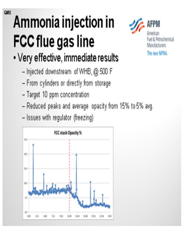
Question 98: What is your experience with the use of ammonia or steam in the FCC flue gas line in order to improve the operation of the ESP? Please comment on system configuration and operational issues
PIMENTEL (CITGO Petroleum Corporation)
We have extensive experience with the use of ammonia in the FCC flue gas line in order to improve the conductivity of the particles and improve the operation of the ESP. We inject ammonia at the target level of 10 parts per million or less. It is very effective at that concentration and has helped us reduce our baseline opacity level from about 15% to less than 10% or 5%. It also reduced the peaks. The peaks that you see in the chart are related to soot blower operations of the waste heat boiler. Thanks to the ammonia, we now operate the soot blowers more often without the fear of violating the opacity limit. So it is also an energy-saving project.
In our unit, the ammonia is injected directly downstream of the waste heat boiler from cylinders or from a storage tank located outside of the FCC battery limits. The only issue I can recall with this operation has been the loss of ammonia flow due to the regulators plugging with ice. If the ammonia is not completely dry, it will freeze in your regulator. That is easy to fix by putting some steam tracing in the lines. The chart shows typical performance before and after starting the injection of ammonia. As you can see in the chart, it helps us operate the soot blowers more often.
BROOKS (BP Refining)
As Sergio mentioned, the common use for putting in steam and ammonia is to reduce the resistivity of the particulate so it can be picked up easier in the ESP. We do not have a lot of experience with steam helping our ESP operations, apart from the example I mentioned about using steam on start-up before meeting temperatures necessary to use ammonia.
We do have quite a bit of experience with ammonia injection. All of our ammonia injection systems are fairly similar because, again, we use the same consultant for the vast majority of our ESPs. We also found that it is key to focus on your ammonia injection system providing good dispersion in the flue gas stack and good vaporization of your ammonia. Typically, all of our systems include heaters for vaporization and metering injection pumps, so we know how much ammonia we are injecting. The systems also include good dispersion nozzles for the flue gas stacks.
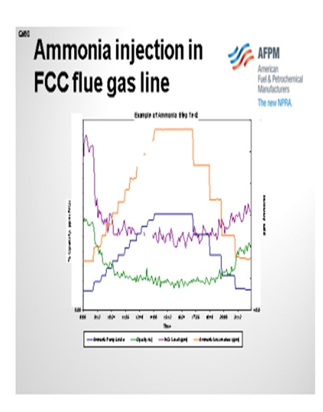
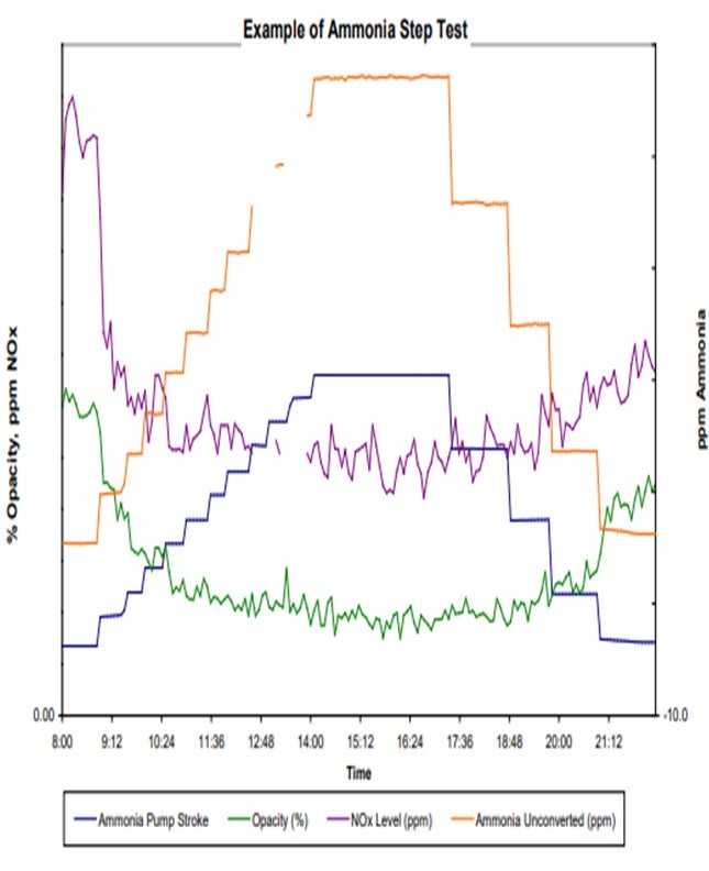
When we use ammonia in our unit, we typically try to optimize it. As shown in the example of an ammonia step test in the slide, the blue and orange lines are essentially the same. They both tell you how much ammonia we are injecting. However, we tend to double-check the meter on the pump stroke versus the actual amount coming in just to make sure we are getting good readings.
You can see that the test includes our stepping up injection rates until we meet a level where we feel like the opacity – the green line – has leveled out. You keep stepping up your ammonia until you believe you have leveled that on opacity, and then you step back down until you feel like your opacity has gone back up. Those are the areas where you would target your ammonia injection rates because you know that is the minimum necessary to maintain your opacity.
I also want to add that I am not sure if other sites have seen instances similar to what we have noticed. Some, but not all, of our sites with ammonia injection into their ESPs also saw a reduction in NOx as a result. It makes sense because you use ammonia in a SNCR (selective non-catalytic reduction) and also in a SCR (selective catalytic reduction) to reduce NOx. However, we do not see it in all of our units.
Those units with high NOx tended to show a good step down and leveling out similar to what we saw with the opacity, which can be seen in the purple line representing NOx. So, you may get an added NOx reduction benefit if you use ammonia on some of your units. We also did the same step test on other units and saw no response to NOx; so, it is not a guarantee.
SCHOEPE (Phillips 66)
I do not have much to add. Halle highlighted all of the points. Phillips 66 has a few installations where we inject ammonia into the ESP. Collection efficiencies were increased by 25% to 50%. It is critical to have good ammonia injection quilts which inject ammonia across the entire duct. Typically, we have not seen any issues with ammonium salt deposition anywhere in the downstream equipment.
MARTIN EVANS (Johnson Matthey Intercat)
To give a contrary comment, I heard a few people talk about the importance of dispersion. We recently had one refiner start ammonia injection and have trouble with the quill. When the quill was removed and the ammonia was injected straight into the nozzle, he got a similar reduction in opacity as he had been getting with the quill. So go figure. It is always the same with the FCC. You can prove something on one unit and then prove the exact opposite in another unit. Another point I want to make is that we have seen that opacity can increase when refiners go to low SOx emissions, typically below 50 ppm and certainly below 20 ppm. This occurs, if you are not using ammonia, because the SO2 (sulfur dioxide) actually acts in the same way as does the ammonia to decrease the resistivity of the catalyst and improve the efficiency of the ESPs. So, when you take out the SO2, you have to replace it with ammonia. Otherwise, you will lose ESP efficiency when you get down to very low SOx levels.
PIMENTEL (CITGO Petroleum Corporation)
We have extensive experience using ammonia in the FCC flue gas line to improve the performance of the ESP. NH3 is a very effective way to improve the conductivity of the flue gas at the levels as low as 10 ppm. In our experience the use of ammonia helped to reduce the flue gas opacity from an average of 15% to less than 5%. Ammonia is injected directly in the flue gas line downstream of the waste heat boiler (at about 500°F) from cylinders or directly from an ammonia storage tank located outside of the unit battery limits. The only operational issue with this system was plugging the regulators with ice, which was solved by steam tracing upstream of the regulator/orifice plate. We do not have experience injecting steam in the flue gas line to improve the operation of the ESP.
BROOKS (BP Refining)
BP does not have a great deal of experience using steam to improve ESP operations. We have one site that uses steam in the ESP during start-up to improve efficiency before the ESP is hot enough to add NH3 injection. This is to prevent possible salt formation that can result from adding NH3 into a cold ESP. The majority of our units use ammonia (NH3) injection successfully to improve ESP collection efficiencies. The purpose of using steam or NH3 injection upstream of the ESP is to condition the particulates by decreasing their resistivity. Decreasing particulate resistivity makes them easier to attract to the walls of the ESP, thus leading to higher collection efficiencies.
As mentioned above, BP uses an industry consultant with a multitude of ESP experience to help guide our ESP operations and optimization efforts. The majority of our NH3 injection systems are similar and follow the consultant’s guidelines, which typically include heaters for vaporization and metering injection pumps. Some sites have basic injection nozzles in the ducts while others have full injection grids. The key considerations for this injection system are around ensuring the injection point provides good dispersion in the flue gas duct and that they NH3 is sufficiently vaporized. Un-vaporized NH3 injection can cause issues with particles remaining on the collecting plates and falling off in chunks or hopper pluggage caused by sticky fines which leads to difficulty evacuating hoppers.
BP has also done a series of NH3 step-tests to optimize NH3 injection. These tests are simple adjustments to NH3 flow rates that are compared to improvements in stack opacity for each step as can be seen in the example graph below. During these tests we have seen that the reduction in opacity with increasing amounts of NH3 injection lines typically lines out at some point, as can be seen in the graph below.
Our experience with NH3 injection has generally been very good at sites with good injection systems. In addition to improvements in opacity with NH3 injections, BP has also seen some reduction in NOx at some of our sites. Generally, we have seen sites with higher base NOx levels see reductions in NOx with NH3 injections and others with lower base NOx levels may not see any change in NOx emissions with NH3 injection.
SCHOEPE (Phillips 66)
Ammonia has been used effectively in a number of refineries to increase electrostatic precipitator (ESP) collection efficiency. Ammonia decreases the resistivity of the catalyst which makes it easier for a catalyst particle to accept a charge. Depending on the ESP design aqueous ammonia injection can increased the ESP collection efficiency by 25% to 50%. A successful installation requires good distribution of the aqueous ammonia. Injection quilts need to be designed to distribute the ammonia equally across the area of the flue gas duct upstream of the ESP and resist catalyst erosion. Deposition of ammonium salts is typically not an issue.
Year
2012
Process
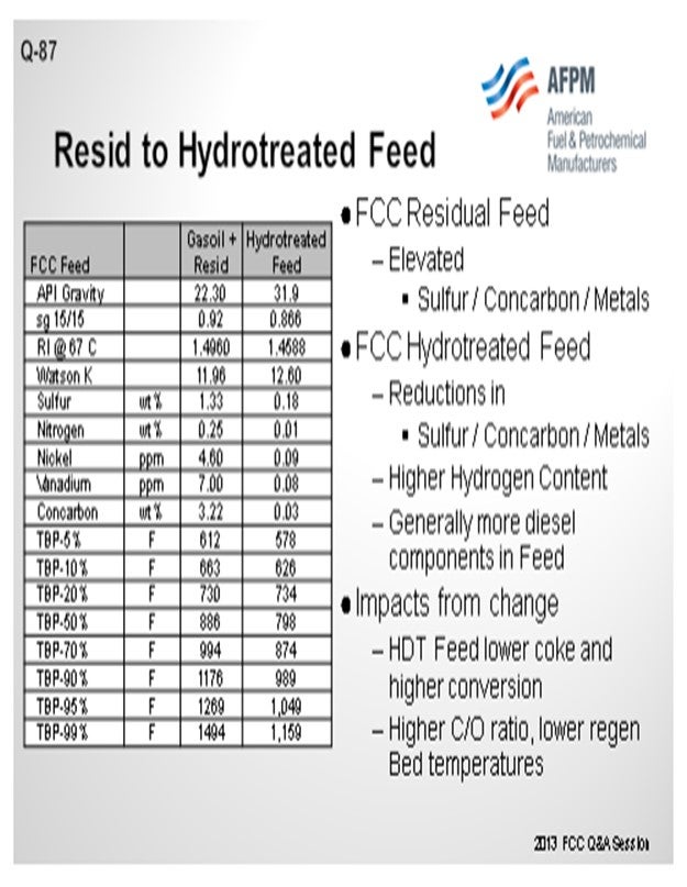
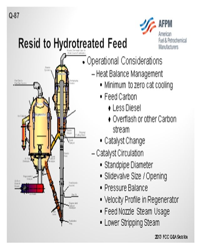
Question 87: The operation of a resid FCC can be challenging as more of its feed is hydrotreated to meet ULSG and ULSD specifications. What changes can be made to improve its operation?
LARSON (KBC Advanced Technologies, Inc.)
For the purpose of this answer, we will look at this as a resid cat cracker that would have a catalyst cooler or be in a two-stage operation. Any increase in feed hydrotreating which increases the portion of hydrotreated feed, or an increase in hydrotreating severity, will obviously improve the feed quality. The slide shows a representative material of a gas oil plus resid and then what it might look like on the basis of a hydrotreated feed. You will notice that by using Watson K or refractive indices, the quality of the feed improves quite substantially. We see that the Concarbon (Conradson carbon) is dropping quite significantly. In those cases, you will have a substantially different coke balance in the unit, and you will see the regenerator fall.
So, what are some of the conditions that you might evaluate to change the operation? One condition is that you will see a much higher cat-to-oil in the unit. Operationally, catalyst circulation itself will go up. The slide valve may need to be increased further. So, then what will be the counter-condition you will need to examine? Can you circulate the catalyst rate that is needed to operate? If you have a two-stage system and a cat cooler, can you keep the cat cooler in operation? Do you just turn it off completely?
Make sure you can get as much trapped diesel out of the unit as possible; because if you distill it in, even if it is only 10%, it will be acting like another cat cooler. With regard to catalyst change, we have a lot of catalyst vendors here. That may be one of the first product you examine in order to maintain the heat balance. You might also consider adding carbon. If you have hydrotreated feed, you can add carbon through the HCO recycle overflash, provided you can maintain the sulfur specifications on your products. You also need to consider the pressure balance to keep the unit operating within targeted range.
In a step change on the existing unit, if you are far enough away from turnaround, you might have to take actions that you would not do in an optimized situation, like reducing the actual steam to the feed nozzle to reduce mixing to allow the addition of carbon. Because it is a situation that exists now and has to be lived with it until the next shutdown, we have clients who have actually pulled steam out of the stripper and let hydrocarbon slip into the regenerator to keep up the profile, which allows them to run the unit. These are non-ideal situations and are done in lieu of mechanical adjustments so you can stay online. Before doing any of the above recommendations, you should consider first a catalyst change.
KOEBEL (Grace Catalysts Technologies)
I want to add one comment about hydrotreated resid. I made a quick query of Grace’s worldwide catalyst database and found some examples of people running hydrotreated resid or partially hydrotreated resid. There were still very, very high levels of metals: much higher than you would consider for a traditional hydrotreated feed operation. Certainly, from a catalyst standpoint, a unit running some hydrotreated resid and a portion of actual resid can still have very high metals; so, you need to make sure you are considering that as part of your solution on the catalyst side as well.
Another phenomenon we see regularly is that the unit running some hydrotreated feed and some resid has a dumbbell-type distribution – a lot of light feed but also some 1300°F plus material – so that type of feed will not behave as if it was blended properly. So, consider the overall distillation of the feed when selecting catalyst as well.
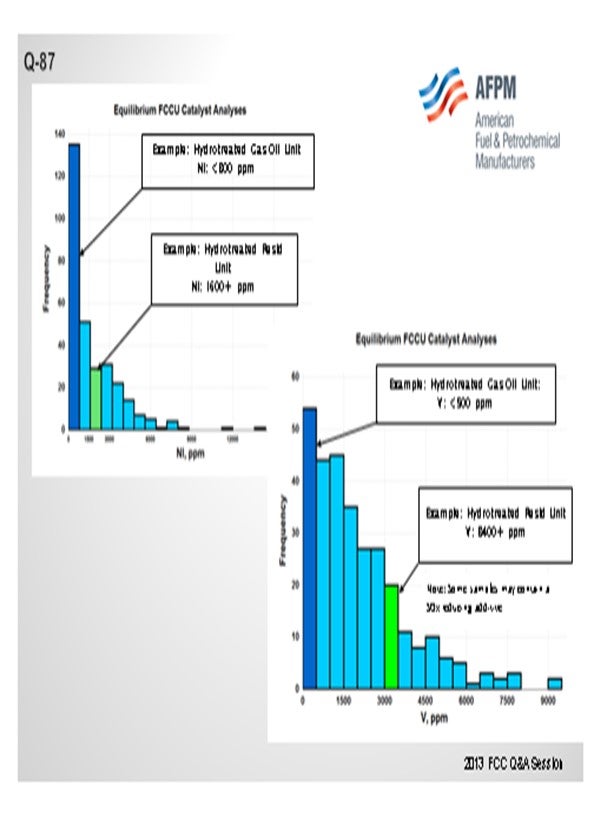
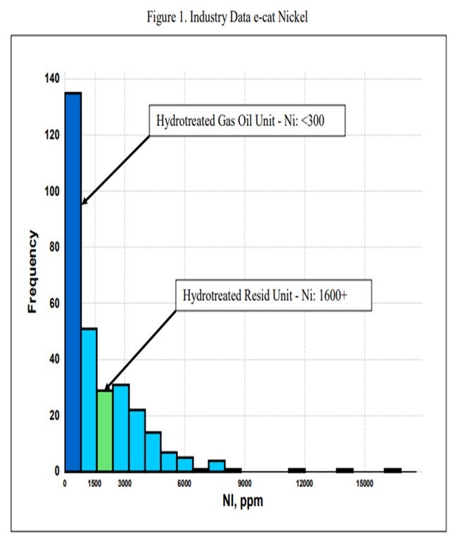
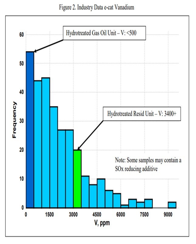
JEFF KOEBEL (Grace Catalysts Technologies)
One catalytic challenge related specifically to resid units that process hydrotreated feed is delivering the proper balance of catalyst activity, metals tolerance, and bottoms cracking. Hydrotreated resid, or a mix of resid and some sort of hydrotreated feed, can still contain a significant amount of contaminant metals. One example of a unit processing hydrotreated resid has in excess of 1600 ppm Ni and 3500 ppm V on e-cat, which is much higher than traditional hydrotreated gas oil operations (Figure 1 and Figure 2). With this level of metals contamination, it is important that the catalyst have proper metals tolerance, which one does not normally think of when considering a hydrotreated feed. Having the proper balance of zeolite and matrix activity is also critical to achieve an optimal level of bottoms conversion. In instances where the feed is a mixture of hydrotreated and untreated resid, the resulting feed blend will not behave at all like a feed with its blended API and K factor. Therefore, the capability to optimize the zeolite and matrix balance in the FCC catalyst becomes even more critical.
MEL LARSON (KBC Advanced Technologies, Inc.)
For the purposes of this answer, the designation of resid FCC will be defined by those units with either a catalyst cooler or a two-stage operation. Any increase in feed hydrotreating (either increased hydrotreater severity or an increased portion of the feed being hydrotreated) will improve the feed quality resulting in a lower regenerator temperature. Resid cat crackers, which are designed to burn large amounts of coke, often have problems maintaining sufficiently high regenerator temperature with treated feeds.
When the coking tendency of the feed drops or lowers dramatically, it is a good time to review the crude and vacuum unit operations and any post-hydrotreating fractionation to ensure that the diesel content of the FCC feed is reduced as much as possible since light boiling feed will reduce regenerator temperature. We have found several instances where a minor revamp of the vacuum unit allowed an increase in the vacuum gas oil cutpoint by up to 90°F (or more). This results in more and heavier charges to the FCC, which will increase regenerator temperature.
The normal considerations with lower regenerator temperatures are catalyst circulation issues and regenerator combustion profiles and carbon removal from the catalyst that are very different than the design basis. Therefore, the objective is how to maintain regenerator temperatures that keep the unit within reasonable operating parameters. Operational changes are defined as follows:
• Minimize heat removal via catalyst coolers or quench systems as much as possible. Longer term and depending upon the situation, eliminating regenerator heat removal system could be considered.
• With two-stage regeneration systems, minimize air rate and coke burning in the first stage and shift it to the second stage so a greater percentage of the coke is burned in the total combustion mode. For single-stage regenerators with cat coolers, move toward total combustion with minimum excess oxygen in the flue gas if the unit is in partial combustion.
• Consider a catalyst change. RFCC (resid FCC) units typically use catalyst with low coke selectivity to help minimize regenerator temperatures. Whenever a significant change in feed quality is anticipated, a catalyst evaluation should be conducted to assure that the best catalyst for the new operation is selected. Moving from a low coke-selective catalyst to a high coke-selective catalyst can add 30°C to 50°C to the regenerator temperature.
• Add slurry recycle to the riser.
• Lower stripping steam.
• Lower dispersion steam.
• And lastly, introducing torch oil (in the extreme case) can be considered. The addition of an external fuel source directly to the regenerator (torch oil) has a deleterious effect on the FCC catalyst.
Lower coke yield or lower regenerator temperatures can be an especially severe problem for units with two-stage regenerators. With some of these designs, some coke must be burned in partial combustion; so, there may well be insufficient heat available to run the unit on gas oil or severely hydrotreated resids. This really highlights the need to consider feed flexibility when designing new units as changes in relative crude prices, crude availability, or product specifications (especially sulfur content) can make resid cracking unattractive.
Despite the drawbacks of reducing stripping steam mentioned earlier, we have at least two clients who, after exhausting the other options, have found it economical to do this rather than continue to charge resid to the FCC. In one case, this was a temporary solution used until a catalyst reformulation could be put into effect. In the other, it is still used as a trim variable.
Hardware changes to consider accommodating higher catalyst flux rates would include, but not be limited to:
• Elimination of heat removal system on regenerator,
• Review of standpipe and slide valve sizing, and
• Expansion of capacity given that the air blower is less constrained.
Consider post-treat options that allow a more carbonatious feed.
Year
2013
Process