
Question 86: What are the advantages and disadvantages of pre-blending FCC additives with FCC catalyst? What is the experience with incorporating FCC additive functionality into the catalyst particles?
KOEBEL (Grace Catalysts Technologies)
Certainly, the obvious advantage of pre-blending additives with your base catalyst is improving your logistics and not handling totes. Another advantage is in not needing an additive loader that you have to maintain. Additionally, pre-blending avoids the possibility of human error in the additive injection process. There are significant drawbacks to doing this as well.

Certainly, if you will be pre-blending additives, the best instance will be when you are using an additive at a constant rate every day. Because if you get into a situation of increasing catalyst additions, you may be over-adding the additives unintentionally and could even get into a bind where you have over-added promoter or ZSM-5.

There are applications for pre-blending additives. Sometimes refiner’s consent decrees call for them to add 10% SOx additive on a daily basis. That was a great example of an application where pre-blending SOx additive worked out very, very well. But certainly, working with your catalyst and additive suppliers will help you come up with what is best for your particular situation.
As far as incorporating additive functionality into the catalyst particles, this is an area where Grace has had a lot of success. In nickel trapping, it is particularly important to have that type of additive functionality. In the catalyst part of this, nickel is not mobile in FCC conditions in the catalyst section; so, you need to trap the nickel where it lands on the FCC catalyst. We have also had good success with our interoperable vanadium trap, which is rare earth based. That trap is depicted in the lower left-hand corner of the slide. The hotspots you see in the picture on the left represent where you find concentrated lanthanum on the surface of the catalyst particle. On the right is the concentrated vanadium. You can see that the two overlap and the vanadium trap is working. We find that having the vanadium trap widely dispersed throughout the catalyst inventory works very well.

We do also have gasoline sulfur reduction technology. That is an additive Grace sells. We do have our SuRCA® family line of FCC catalysts which incorporates that functionality into the catalysts as well. That is one area where people generally tend to use it on a day-in and day-out basis at the same concentration. And where people are long-term gasoline sulfur reduction technology users, we tend to incorporate that functionality into the catalyst.
Finally, Grace recently developed our newly achieved catalyst platform for tight oil and unconventional feeds. One of the comments we sometimes get from refiners is that octane and alkylation of feed stock shortages become an issue. So, in response, we developed the dual zeolite catalyst that will incorporate some isomerization zeolite into the catalyst particle. We find that we can get maximum octane and butylenes for the alkylation unit without the traditional increase in propylene that you would see when using a traditional ZSM-5-based zeolite additive. We have had good success with this product in development, and we are expecting the first commercial trial of it coming really soon.
BULL (Valero Energy Corporation)
As far as pre-blending additives, to reiterate what Jeff said, I will say that if it one being used every day, then add a base amount with the catalyst. What we have done, even when pre-blending, is to always have a loader because we never know more additive might need to be used. Situations do occur that necessitate totally changing the supply chain, taking the additive out of the pre-blend, and then adding it at a different ratio. The only caveat I will add is that even if you are pre-blending, just maintain the facilities so that you will be able to put in the additive.
The second half of the question asks about incorporating FCC additive functionality. We have had extremely positive experiences with trials at various sites, and we are currently using this variety of catalyst at several of them. With reference to metals trapping, we have incorporated that type of additive into the base catalyst for many years; but more recently, we have begun using more of the C4/butylene maximization kinds of additives incorporated into our base catalysts. Again, we have had multiple trials. I cannot really get into all the details of it, but it has been a very big success.

MARTIN EVANS (Johnson Matthey INTERCAT, Inc.)
My experience has been that in North America, most refiners generally tend to keep their additives separate from their fresh catalysts, adding them separately through their own addition systems, as Jeff advocated. I think that pays off. My own experience in this area, from when I was an FCC engineer in the U.K., really taught me that lesson very severely. We had just started using ZSM-5 additives. Because the refinery did not want to pay to put in the addition system, they decided to pre-blend. That worked great until our downstream LPG (liquefied petroleum gas) processing unit broke down. Then at that point, we were left with more LPG than we could handle, and the cost to us – in terms of lost profitability from having to turn down the FCC operation to keep the LPG under control – was a hell of a lot more than it would ever have cost us to put in an addition system. That really taught us a lesson about short-term economics. You think you are gaining something in the short-term by not putting in a loader, but it is a false economy. You definitely end up paying for it long-term.
ROBERT “BOB” LUDOLPH [Shell Global Solutions (US) Inc.]
For your awareness, if you are considering the use of, or have been using, e-cat, pay particular attention to the chemical properties. The presence of certain additives in the e-cat can be indicated like platinum for combustion promoter, phosphorus for ZSM-5, and copper for NOx reduction. Also be aware that the additive activity may be in excess of your need, and you many need to create other operating issues. For example, NOx emissions can take an unexpected step up if the pre-blended combustion promoter activity is too high.
KEN BRUNO (Albemarle Corporation)
Indeed, Best Practices for additive addition are highly influenced by the additive type and any kind of refinery-specific factors. Albemarle offers a full line of not only additive products, but also integrated products with integrated technologies. Again, please consult the Answer Book for a description and our recommendation for when, where, and how to use all these products.
ALEXIS SHACKLEFORD (BASF Corporation)
With regard to the second half of that question about experience with incorporating additive functionality in the catalyst particle, BASF uses a separate particle vanadium trap. It allows the refiner to have additional catalyst flexibility when the vanadium trap is not incorporated with the active catalyst particles.
BART de GRAAF (Johnson Matthey INTERCAT, Inc.)
In the case of metal excursion, we find that it is beneficial to have the possibility of adding additives to mitigate deleterious metal effects. Various base catalysts can contain a built-in metal trap, and there are various additives available which trap metals. When using an additive, you can react quickly to metal excursions when you use, for example, a different type feed. There are advantages of trapping metals on a separate particle instead of keeping them in close proximity to the base catalyst particles containing Y-sieve.
JEFFREY BULL (Valero Energy Corporation)
Pre-blending additives that are used every day for operational controls (combustion promoter), for regulatory/environmental controls (SOx reduction additive), or for yield selectivity changes (ZSM-5) at a base amount is advantageous, because it reduces the complexity of getting those additives in the unit. I would always recommend having facilities be able to add an individual additive in addition to the pre-blended amount in the case of an upset or for a “quick boost”. We have very positive experience with incorporating FCC additive functionality in the catalyst particle. I am not able to relate specific details; but overall, we have had favorable experiences with this type of catalyst. We have completed trials with positive results and are looking to expand to other units.
JEFF KOEBEL (Grace Catalysts Technologies)
Grace has extensive experience with pre-blending and incorporation of FCC additive functionality into the catalyst particle. Specifically in this discussion, we will focus on:
JEFF KOEBEL (Grace Catalysts Technologies)
Grace has extensive experience with pre-blending and incorporation of FCC additive functionality into the catalyst particle. Specifically in this discussion, we will focus on:
• SOx reduction,
• LPG olefins maximization,
• CO promoter,
• Metals traps, and
• Gasoline sulfur reduction.
Pre-blending of separate additives is advantageous when they are used at a fairly constant rate on a continuous basis. This pre-blending eliminates operator action, minimizes the possibility of over- or under-dosing according to plan, reduces the need for additional additive loader equipment, and eliminates the need to handle totes. If the need for the additive is consistent but the usage rate is variable, it is possible to pre-blend additive functionality into the catalyst at a minimum concentration and then supplement with additional dosing as required. A potential scenario for this would be if a refiner is regularly adding a SOx-reducing additive. One may consider pre-blending the minimum amount and supplement with additional dosing via totes to maintain the desired SOx emission level. Finally, purchasing your FCC base catalyst and additives from a single source provides for single-point accountability for your FCC catalyst and additive needs.
If the additive is only used on a spot basis, or if the fresh catalyst addition strategy changes, it is certainly possible to over-add or under-add an additive in a pre-blend setup. Some potential operational concerns are prematurely hitting production limits with ZSM-5 or elevated NOx emissions from overdosing combustion promoter. Either scenario can be managed. We recommend working with your vendor’s technical service representative to optimize your logistics.
Grace has extensive experience with incorporating additive functionality directly into the FCC catalyst particle. We have been extremely successfully in incorporating both nickel and vanadium metals trapping into the catalyst system. In the matter of trapping nickel, it is important to trap the contaminant nickel in the FCC catalyst particle because nickel is not mobile in the catalyst section and needs to be trapped where it is initially cracked on to the catalyst. To do this, Grace utilizes a proprietary alumina that absorbs the nickel into the catalyst particle forming a stable nickel aluminate that is no longer active for dehydrogenation reactions. Grace has been highly successfully in utilizing this technique. Currently, more than 65% of our worldwide customers are taking advantage of this technology.
For vanadium trapping, incorporating a trap on the catalyst system can provide widely dispersed trapping capability to more effectively reduce the negative impacts of the contaminant. Grace’s IVT-4 is an integral rare earth-based vanadium trap that converts contaminant vanadium into an inert rare earth vanadate, greatly reducing zeolite deactivation and coke and gas production. Grace is currently using IVT-4 in 60%+ of our worldwide catalyst formulations.
Gasoline sulfur reduction is another technology that can be readily incorporated into the FCC catalyst particle. Grace’s SURCA® catalyst can be used to reduce gasoline sulfur by 25 to 35% on full-range gasoline. Refiners can utilize this technology to potentially extend FCC feed hydrotreater catalyst life, reduce naphtha hydrotreater severity to preserve octane, or run a higher FCC feed sulfur during FCC feed hydrotreater outages. Typically, these applications require the technology consistently over an extended period, so incorporating this technology into the catalyst formulation is appropriate.
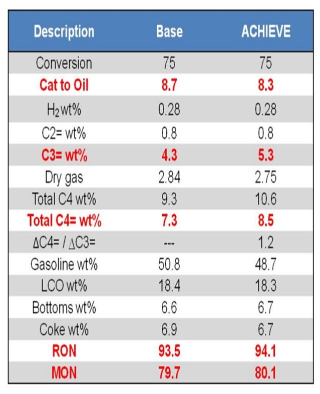
Finally, Grace has recently developed a new catalyst platform for unconventional feeds called ACHIEVE™. A common challenge reported by refiners operating on unconventional feeds, such as shale or tight oil, is a loss of gasoline pool octane, often caused by reduced volume of alkylation feedstock. ACHIEVE™ catalyst can be formulated with multiple zeolites to deliver an optimal balance of LPG-to-gasoline yield and an optimum level of butylenes to keep the alky unit full and maintain refinery pool octane. Incorporation of isomerization activity into the catalyst particle itself results in a more desirable yield pattern than would be realized by use of a traditional octane-boosting FCC additive. An example of the yield shifts possible with this technology is found in Table 1. At constant conversion, ACHIEVE™ delivers higher gasoline octane and higher LPG olefins, with preferentially more butylenes over propylene, providing more total octane barrels for the refinery.
RYAN NICKELL, CAREL POUWELS, and KEN BRUNO (Albemarle Corporation)
Best Practices for additive addition are highly influenced by additive type and refinery specific factors. For environmental applications like SOx control, excursions must be avoided. Separate addition offers flexibility and can also be tailored for feed quality and trouble situations. Pre-blending is utilized in limited cases where a refiner prefers to avoid operating and maintaining a second loader. In these cases, the refiner may also have less strict emissions requirements.
For after-burn control, many refiners prefer to have a separate additive that can be quickly added during emergency situations. If a problem is chronic, pre-blending is a viable and preferable option. Furthermore, chronic problems are well managed by technologies like Albemarle’s InsituPro™ whereby the additive is incorporated into the catalyst particle. In such cases, the active metal is deposited on every single catalyst particle, and optimal distribution in inventory is obtained.
Metal traps capture nickel and vanadium that degrade catalyst performance. The Best Practice with metal traps is direct incorporation into the catalyst. Vanadium species attack zeolite in the regenerator, and incorporation of the metal trap into the attack zone typically works best. Albemarle’s SMR technology incorporates vanadium capture and nickel control directly in the catalyst. Pre-blending is an excellent option when using bottoms upgrading additives like Albemarle’s BCMT™ technology or olefins-octane additives like DuraZOOM™.
Pre-blending simplifies logistics at the refinery and avoids the maintenance and overhead associated with operation of a second loader. Many refiners pleased with BCMT™ performance have ultimately transitioned to a full catalyst solution like UPGRADER™ for maximum bottoms cracking.
While the use of separate additives often offers flexibility to the refiner, in some cases this can lead to suboptimal performance. One salient example is the refiner who believes he can have best of both worlds and simply change between max gasoline and high or max propylene mode by the use of additives. When operating in a high or maximum propylene mode the use of a separate additive, combined with the max gasoline catalyst, will lead to suboptimal propylene yields due to activity dilution and inefficient chemistry. A true max propylene catalyst, like Albemarle’s AFX™, makes use of a proprietary zeolite technology (ADZT-150) with high activity and low hydrogen transfer structured to produce unsurpassed propylene, which never would have been achieved by the aforementioned combination of catalyst and separate additive.
Lastly, for refiners seeking maximum butylenes with minimal gasoline loss, together with octane improvement, Albemarle’s ACTION® catalyst, with its specialized zeolite technology (ADZT-100), is preferred. The use of this specialized zeolite technology optimizes the chemistry and maximizes performance compared with the use of a base catalyst and separate additive.
Year
2013
Process

Question 87: The operation of a resid FCC can be challenging as more of its feed is hydrotreated to meet ULSG and ULSD specifications. What changes can be made to improve its operation?
LARSON (KBC Advanced Technologies, Inc.)
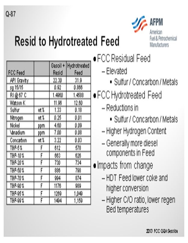
For the purpose of this answer, we will look at this as a resid cat cracker that would have a catalyst cooler or be in a two-stage operation. Any increase in feed hydrotreating which increases the portion of hydrotreated feed, or an increase in hydrotreating severity, will obviously improve the feed quality. The slide shows a representative material of a gas oil plus resid and then what it might look like on the basis of a hydrotreated feed. You will notice that by using Watson K or refractive indices, the quality of the feed improves quite substantially. We see that the Concarbon (Conradson carbon) is dropping quite significantly. In those cases, you will have a substantially different coke balance in the unit, and you will see the regenerator fall.
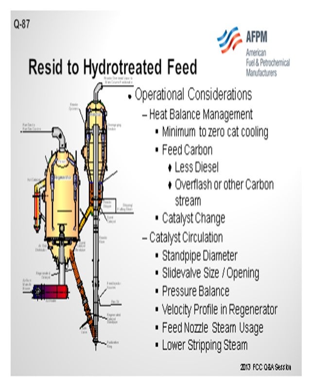
So, what are some of the conditions that you might evaluate to change the operation? One condition is that you will see a much higher cat-to-oil in the unit. Operationally, catalyst circulation itself will go up. The slide valve may need to be increased further. So, then what will be the counter-condition you will need to examine? Can you circulate the catalyst rate that is needed to operate? If you have a two-stage system and a cat cooler, can you keep the cat cooler in operation? Do you just turn it off completely?
Make sure you can get as much trapped diesel out of the unit as possible; because if you distill it in, even if it is only 10%, it will be acting like another cat cooler. With regard to catalyst change, we have a lot of catalyst vendors here. That may be one of the first product you examine in order to maintain the heat balance. You might also consider adding carbon. If you have hydrotreated feed, you can add carbon through the HCO recycle overflash, provided you can maintain the sulfur specifications on your products. You also need to consider the pressure balance to keep the unit operating within targeted range.
In a step change on the existing unit, if you are far enough away from turnaround, you might have to take actions that you would not do in an optimized situation, like reducing the actual steam to the feed nozzle to reduce mixing to allow the addition of carbon. Because it is a situation that exists now and has to be lived with it until the next shutdown, we have clients who have actually pulled steam out of the stripper and let hydrocarbon slip into the regenerator to keep up the profile, which allows them to run the unit. These are non-ideal situations and are done in lieu of mechanical adjustments so you can stay online. Before doing any of the above recommendations, you should consider first a catalyst change.
KOEBEL (Grace Catalysts Technologies)
I want to add one comment about hydrotreated resid. I made a quick query of Grace’s worldwide catalyst database and found some examples of people running hydrotreated resid or partially hydrotreated resid. There were still very, very high levels of metals: much higher than you would consider for a traditional hydrotreated feed operation. Certainly, from a catalyst standpoint, a unit running some hydrotreated resid and a portion of actual resid can still have very high metals; so, you need to make sure you are considering that as part of your solution on the catalyst side as well.
Another phenomenon we see regularly is that the unit running some hydrotreated feed and some resid has a dumbbell-type distribution – a lot of light feed but also some 1300°F plus material – so that type of feed will not behave as if it was blended properly. So, consider the overall distillation of the feed when selecting catalyst as well.
JEFF KOEBEL (Grace Catalysts Technologies)
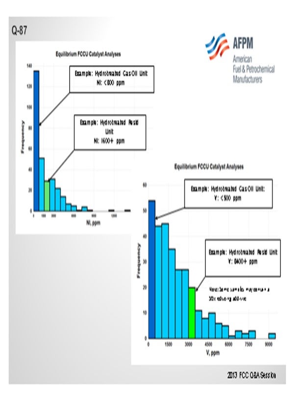
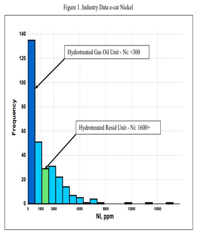
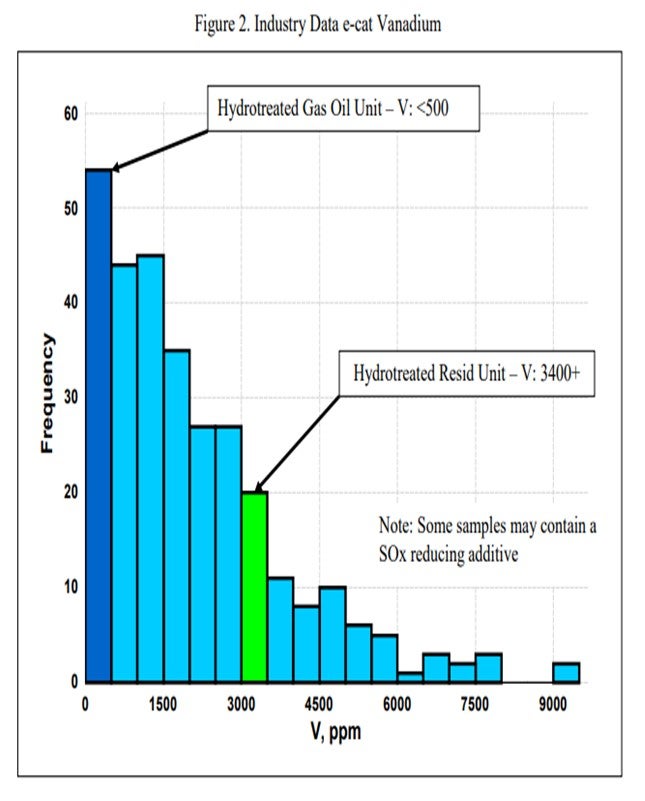
One catalytic challenge related specifically to resid units that process hydrotreated feed is delivering the proper balance of catalyst activity, metals tolerance, and bottoms cracking. Hydrotreated resid, or a mix of resid and some sort of hydrotreated feed, can still contain a significant amount of contaminant metals. One example of a unit processing hydrotreated resid has in excess of 1600 ppm Ni and 3500 ppm V on e-cat, which is much higher than traditional hydrotreated gas oil operations (Figure 1 and Figure 2). With this level of metals contamination, it is important that the catalyst have proper metals tolerance, which one does not normally think of when considering a hydrotreated feed. Having the proper balance of zeolite and matrix activity is also critical to achieve an optimal level of bottoms conversion. In instances where the feed is a mixture of hydrotreated and untreated resid, the resulting feed blend will not behave at all like a feed with its blended API and K factor. Therefore, the capability to optimize the zeolite and matrix balance in the FCC catalyst becomes even more critical.
MEL LARSON (KBC Advanced Technologies, Inc.)
For the purposes of this answer, the designation of resid FCC will be defined by those units with either a catalyst cooler or a two-stage operation. Any increase in feed hydrotreating (either increased hydrotreater severity or an increased portion of the feed being hydrotreated) will improve the feed quality resulting in a lower regenerator temperature. Resid cat crackers, which are designed to burn large amounts of coke, often have problems maintaining sufficiently high regenerator temperature with treated feeds.
When the coking tendency of the feed drops or lowers dramatically, it is a good time to review the crude and vacuum unit operations and any post-hydrotreating fractionation to ensure that the diesel content of the FCC feed is reduced as much as possible since light boiling feed will reduce regenerator temperature. We have found several instances where a minor revamp of the vacuum unit allowed an increase in the vacuum gas oil cutpoint by up to 90°F (or more). This results in more and heavier charges to the FCC, which will increase regenerator temperature.
The normal considerations with lower regenerator temperatures are catalyst circulation issues and regenerator combustion profiles and carbon removal from the catalyst that are very different than the design basis. Therefore, the objective is how to maintain regenerator temperatures that keep the unit within reasonable operating parameters. Operational changes are defined as follows:
• Minimize heat removal via catalyst coolers or quench systems as much as possible. Longer term and depending upon the situation, eliminating regenerator heat removal system could be considered.
• With two-stage regeneration systems, minimize air rate and coke burning in the first stage and shift it to the second stage so a greater percentage of the coke is burned in the total combustion mode. For single-stage regenerators with cat coolers, move toward total combustion with minimum excess oxygen in the flue gas if the unit is in partial combustion.
• Consider a catalyst change. RFCC (resid FCC) units typically use catalyst with low coke selectivity to help minimize regenerator temperatures. Whenever a significant change in feed quality is anticipated, a catalyst evaluation should be conducted to assure that the best catalyst for the new operation is selected. Moving from a low coke-selective catalyst to a high coke-selective catalyst can add 30°C to 50°C to the regenerator temperature.
• Add slurry recycle to the riser.
• Lower stripping steam.
• Lower dispersion steam.
• And lastly, introducing torch oil (in the extreme case) can be considered. The addition of an external fuel source directly to the regenerator (torch oil) has a deleterious effect on the FCC catalyst.
Lower coke yield or lower regenerator temperatures can be an especially severe problem for units with two-stage regenerators. With some of these designs, some coke must be burned in partial combustion; so, there may well be insufficient heat available to run the unit on gas oil or severely hydrotreated resids. This really highlights the need to consider feed flexibility when designing new units as changes in relative crude prices, crude availability, or product specifications (especially sulfur content) can make resid cracking unattractive.
Despite the drawbacks of reducing stripping steam mentioned earlier, we have at least two clients who, after exhausting the other options, have found it economical to do this rather than continue to charge resid to the FCC. In one case, this was a temporary solution used until a catalyst reformulation could be put into effect. In the other, it is still used as a trim variable.
Hardware changes to consider accommodating higher catalyst flux rates would include, but not be limited to:
• Elimination of heat removal system on regenerator,
• Review of standpipe and slide valve sizing, and
• Expansion of capacity given that the air blower is less constrained.
Consider post-treat options that allow a more carbonatious feed.
Year
2013
Process
Question 88: What FCC products are candidates for blending into jet fuel? What are the limitations and considerations?
LARSON (KBC Advanced Technologies, Inc.)
A review of our clients worldwide did not find any client that was blending any FCC product with just sweetening into jet. Limiting issues would be olefins (gum formation) and aromatic and potentially naphthalene content of unhydrotreated FCC jet boiling range components. Hydrotreated FCC product has the potential to be blended to jet provided the blended product meets the jet specification closely monitoring gum, aromatics, smoke, and/or naphthalene content. Some corporate policies prohibit any cracked stocks blended to jet fuel.
Year
2013
Process
Question 89: How are FCC simulation models being used as part of routine performance monitoring and optimization?
BULL (Valero Energy Corporation)
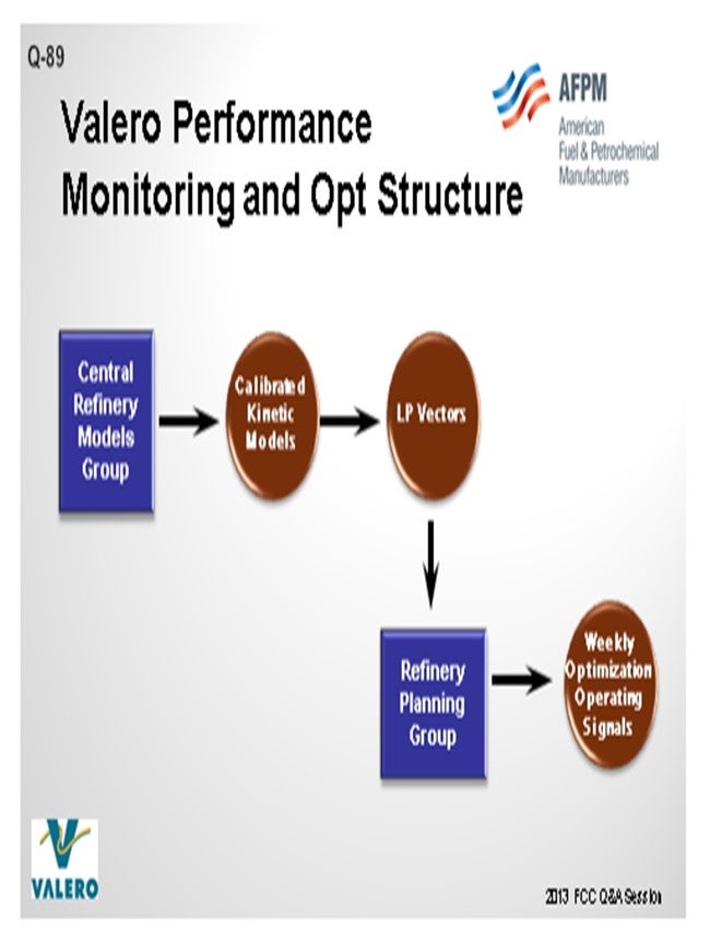
At Valero, we have a centralized group in the Planning & Economics area that is responsible for the kinetic modeling for all of the major process units. The primary driver behind the kinetic models at Valero is to get good data into our LP (linear program) models. The data from the FCC simulation is translated into LP vectors, which are used by our LP group to build LP models for each refinery. Using this data, we then do all of our crude selection, as well as our weekly, one-month, and three-month optimization plans in the LP.
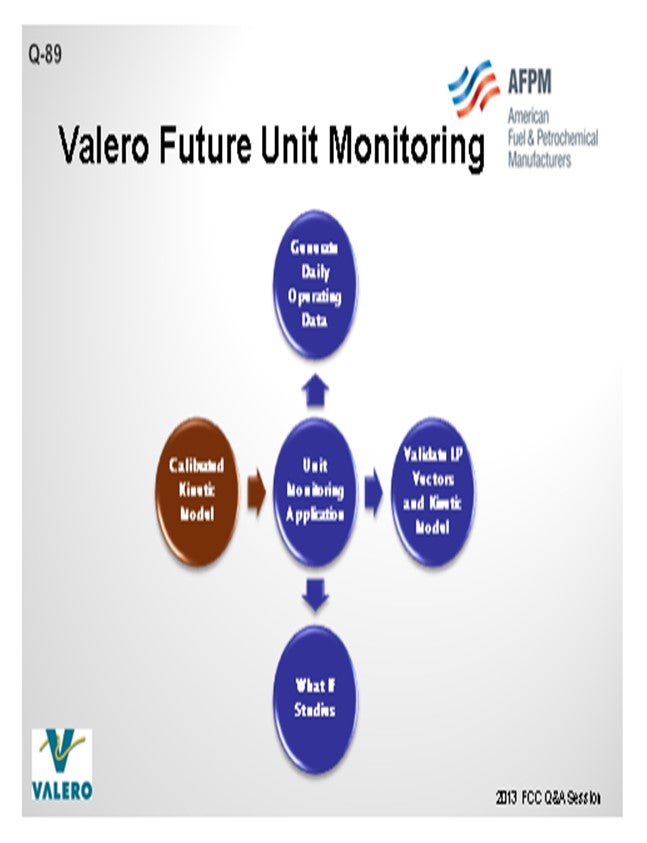
The other influence on simulation models is the engineers who use kinetic models at the refineries and also at the corporate level for different applications. Our group calibrates the kinetic models that are used throughout the company. We have put the kinetic models into unit monitoring applications at Valero to validate LP vectors. These models are also used to conduct what-if studies. The monitoring application also helps us generate our daily operating data. Usage varies greatly amongst the plants at Valero. Some of our refineries are running the kinetic models on a weekly basis. There are other plants that have probably not touched the kinetic model in the entire eight years that I have been at Valero; so, it is hit or miss.
One of our main goals is to train the engineers to leverage kinetic models to do optimizations, look at case studies, or troubleshoot. We need to make it easier for them to use so they will utilize the kinetic models. That is why we have a central group. It is our job to calibrate the model, ensure its accuracy, and then put it in a format that is easy to use.
STEVE GIM (Technip, Stone & Webster)
I have had the luxury of observing more than 200 units around the world over the last 20- plus years. As Jeff alluded, there is a great variation in terms of the quality of data that we get from our customers and how we go about using it to propose or benchmark future changes. Ideally, you would like to have test-run quality data and a stable unit operation associated with laboratory data, but this is not always the case. In terms of the actual use of the kinetic model for optimization and proposal of the operational changes, that would be the most ideal way to look at the operation. But in the absence of these conditions (for example, we only had access to raw pi data), another extreme way to monitor and engage their performance would be either simple time-based benchmarking or statistical benchmarking. My Answer Book response includes actual examples of these different types of benchmarking, ranging from easy to hard. For the sake of time, you can look at those examples and definitions at your convenience.
STUART FOSKETT (BASF Corporation)
I want to add an additional use that we have in service. We use the FCC simulation model from KBC. We have had a very successful experience using a catalyst database that we developed for catalyst factors for all of our various technologies, in combination with the optimizer, to fine-tune offerings for catalyst reformulations.
KEN BRUNO (Albemarle Corporation)
While some already use models, Albemarle strongly encourages all refiners to use their simulation model to do very careful post-audits, particularly around catalyst changes. Make sure that what got in the unit is, for example, what your laboratory would show in catalyst testing. It is critical to post-audit your units to make sure you are making the right decisions. If lab testing is also involved, use these results to make adjustments to how you translate your lab data to commercial projections.
LARSON (KBC Advanced Technologies, Inc.)
Since we were mentioned, one of the other strong values beyond the catalyst evaluation—the kinetic modeling—the platform actually gives you an extreme value in troubleshooting other elements of the unit: cycle velocities and bed velocities. The other values are gotten with kinetic modeling and go beyond simple yields. Based on my experience at KBC, I echo what Jeff said. Quite frankly, with the age of computers, kinetic models are actually underutilized. We are not getting the value of the information available, particularly as a training tool.
As younger engineers are coming through, using a model to train with is a safer alternative to adjusting an operating unit. You can go out and cultivate the models to teach them some of the fundamentals of the unit processing, so they will become better engineers in a more rapid startup into the process. We advocate not just for the purpose of kinetic modeling, but also for the training and troubleshooting aspects, to help you make a long-term profit potentially in your refinery.
ROBERT “BOB” LUDOLPH [Shell Global Solutions (US) Inc.]
When it comes to model calibration/fitting, are unit material balances used or are special tests surveys conducted? Once calibrated, do you attempt to validate the model with newly collected plant data?
BULL (Valero Energy Corporation)
Bob, to address that with the most recent version I will tell you that we utilize KBC models for all of our applications. The recent version 4.1 that is being implemented in our system contains a data reconciliation function, so we are using plant data to feed data reconciliation functions. The data reconciliation function actually trues up the mass balance to 100% before any information goes into the model. Within that platform, we also have designed the capacity for you to bring your data directly from the historian into the kinetic model. There is also data conditioning so we can go through and trap errors in the data. We can use data from a different timeframe when you have a bad flue gas analysis or a TI (temperature indicator) has failed. One of the benefits of the model is that it has allowed us to pin down the location of bad indicators in the laboratory or if it is a TI or flow meter. By performing this data reconciliation, we have more information to identify these issues.
In the past, engineers tried to show this on spreadsheets and then justify it with unreconciled plant data. Now we have it all on a database, so we know where the meters are off when doing the reconciliation. You also have the whole heat balance function which also goes into the evaluation, and you can back into some of your thermocouples and other analyses. Having historical data helps us with our justification to get meters or indicators fixed.
J.W. “BILL” WILSON (BP Products North America Inc.) I would like to ask Jeff for a little bit more clarification. As I understand, your group calibrates the models, generates the LP vectors, and puts them into the LP. Do you perform the actual LP work as well or turn it over to the refinery to operate?
BULL (Valero Energy Corporation)
We have a central LP group that is separate from our Kinetic Model group, so we have people who specialize in just the LPs. That is where the interface comes between our groups. We will generate the data and then check it ourselves. When we send it over to them, there is another check that is done inside the LP; so, there are two rounds before it actually gets sent to the plant.
J.W. “BILL” WILSON (BP Products North America Inc.)
But then the plant actually uses the LP for its short-term planning?
BULL (Valero Energy Corporation)
That is correct. All the planning work is done at the plant. We purchase all of our crude centrally, so that group is a strong user of these LPs as well.
JOE McLEAN (BASF Corporation)
I agree with all the good comments that have been said. We do use the KBC model extensively and incorporate it into all of our other data management systems that use for tech service, but there are drawbacks as well. One of the drawbacks of the model is that it is a steady-state predictive model. It will give you a prediction, but then it will assume that you will just sit there at those fixed conditions until you get to steady state. Of course, FCCs in the real world never run that way.
So, what we found works very well as a companion tool to accompany with the model is to include statistical analysis and multi-variable statistical regression, which is not that scientific by any means, but which is much better at handling transients. Just depending on the specific unit and how well it runs at constant conditions or how far it deviates from that, we may use one versus the other, or a combination of both, to get the best compromised solutions.
LARSON (KBC Advanced Technologies, Inc.)
To add to Bob’s point, one of the concerns that refiners have in collecting data is that they are going to overload the lab with certain laboratory analysis; so, there has been a trend to reduce the amount of lab schedules. I have personally done this. You can sequence your lab collection information so that it does not change the lab schedules or overload the lab. As a result, you can get weekly rigorous test data that is of high quality. If you look at your lab schedule appropriately and mirror what Jeff said Valero is doing in reconciliation of your data, as well as fine-tune the instruments that exist, you could have a reliable, high-quality set of data on a routine basis. But really, go to the lab work to make sure that you do not have the ghost of too many lab samples going in.
JEFFREY BULL (Valero Energy Corporation)
At Valero, we have a Central Refinery Models Group that is part of our Planning & Economics organization. The Refinery Models Group is responsible for the maintaining the kinetic models for every major process unit. FCC simulation models are used as part of routine optimization in two ways. As part of our planning process, the LP models are updated using data generated from the kinetic models. The LP models are used for refinery optimization on a weekly basis. This is an established work process used at all of our sites.
The other way that FCC simulation models are used for optimization is at the process engineer level. This is done in a less formal manner and varies from site to site. Some sites look at the unit performance on a weekly basis or conduct periodic case studies, and other Process Engineering departments do not use the kinetic models. It really depends on the culture at that site and the actual process engineer. As far as routine monitoring, we have recently explored using the kinetic models as a backbone for mass and heat balancing FCC units and then comparing actual performance to model predictions. We see benefits in establishing this work process but still need to quantify the best means to roll this out to our system.
STEVE GIM (Technip Stone & Webster)
Usage of FCC simulation models has to be put into a context of what is workable for day-to-day operation and what is not. For proper usage of FCC simulation models, it is prudent to have test-run quality data with unit stability and accurate lab data that correspond to the set of data we want to analyze. In the absence of these two conditions, we use descriptive and statistical analysis of available data on day-to-day basis. As required, FCC simulation models are used in three main areas of performance monitoring and optimization: (1) analyzing and benchmarking the performance of the FCC unit, (2) recommendations for improved unit performance, and (3) routine updates of FCC sub-model vectors in refinery LP.
Monitoring and Benchmarking
Time-Based Benchmarking
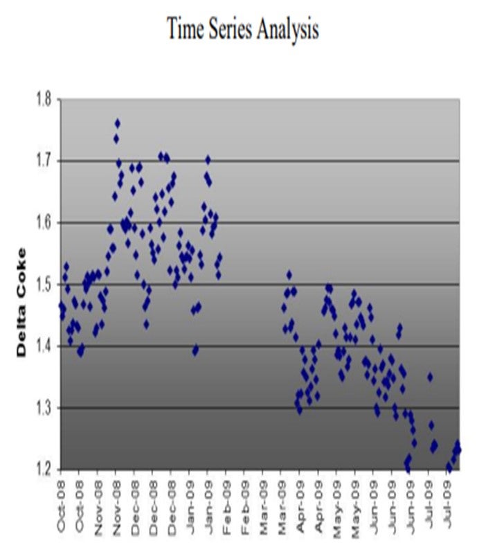
Time-based benchmarking offers visual interpretation of change in both the inputs (feed, catalyst, hardware changes, and independent operating variables, for example) and corresponding outputs (yields and dependent operating variables). These are simple plots that are routinely produced as part of weekly reports. Some of the examples are shown for clarity:
Statistical Benchmarking
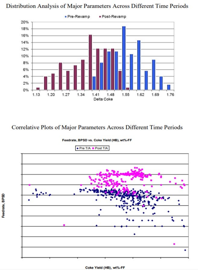
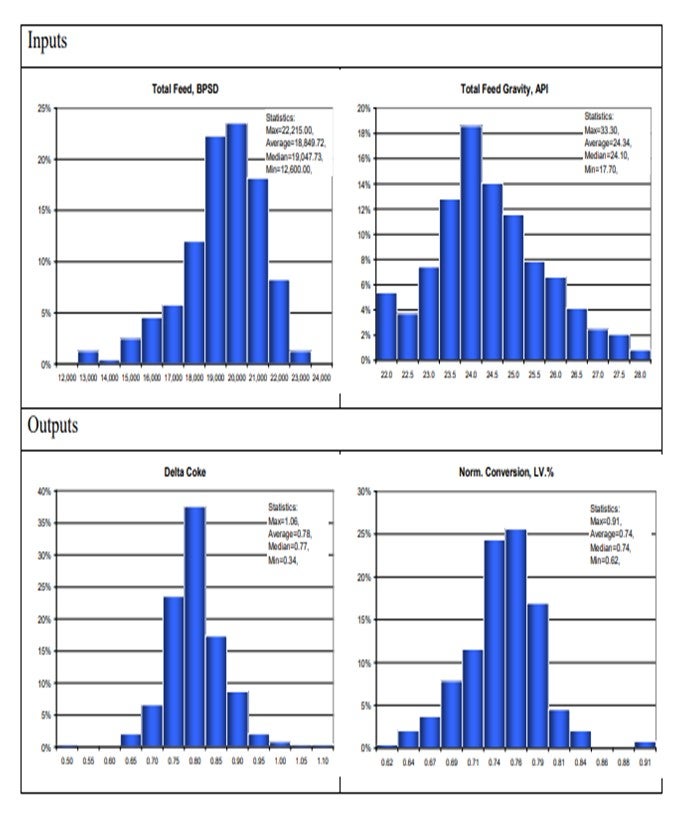
Statistical analyses of various operating parameters serve several purposes. First, provide deeper understanding of distribution in both inputs and outputs of the unit has operation, as shown on the charts below.
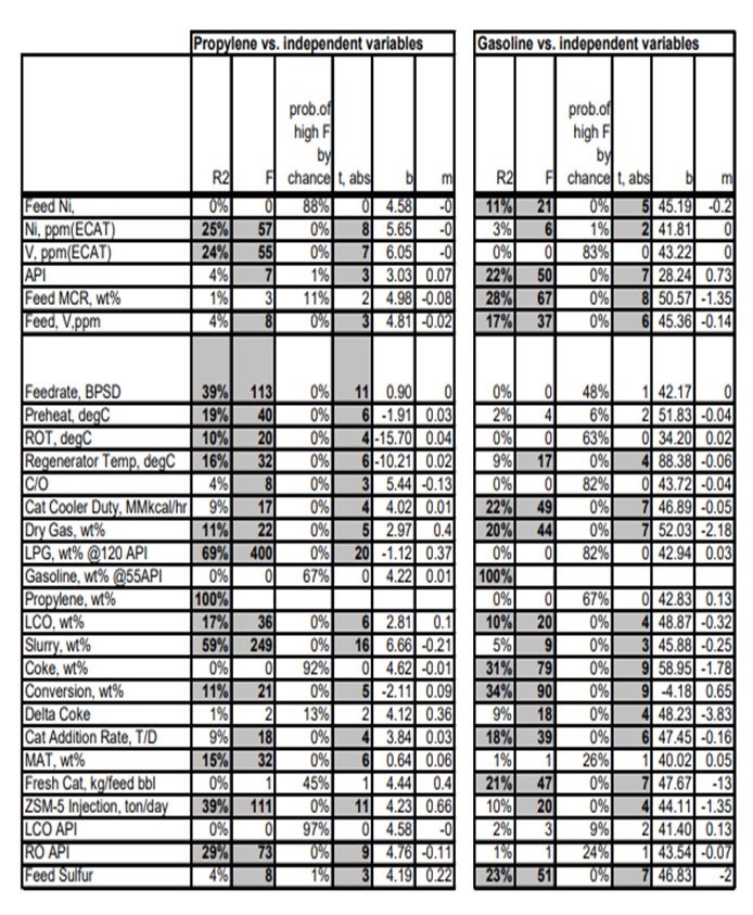
Secondly, create potentially valuable correlations, which are illustrated below:
Physical Benchmarking
Periodic check of the unit performance against various hardware of each FCC identifies both the bottlenecks and opportunities to improve the operation by installation of new technologies and/or revamping of the existing hardware. Yields and operating conditions can be checked against our physical simulation of the FCC as it is actually built. Catalyst fluxes, superficial velocities, and residence times in stripper and regenerator bed are some of the examples of physical attributes of as-built model against industry-accepted criteria.
Kinetic Benchmarking
Technip utilizes an in-house kinetic model co-developed with Axens, IFP, and Total for FCC yield prediction. Periodic “tuning” of the model using the actual operating data serves three purposes: (1) benchmarking the current performance of the unit in various key performance indicators, (2) forecasting and/or recommending future operation of the unit from fine-tuning operational parameters and/or inputs (feed blends, for example), and (3) back-testing the model to close the gap between predicted versus actual to fine-tune the capabilities of the kinetic model built specific for each unit.
Reconciliation
Sizable shifts in feedstock properties, unit hardware, and operating conditions are reconciled using simulation models. Kinetic models can segregate individual effects to better understand the differing contribution of major shifts.
Update of LP Vectors for FCC Sub-model
Updates of the FCC sub-model of the linear program (LP) can be provided by FCC models. Perturbations of bulk feed properties and operating conditions, as well as their resulting yields vectors, are provided for the LP. They provide valuable refresh of FCC’s operations upon a step change in the feed qualities and/or hardware changes that provide a sizable shift in the unit has performance.
ALAN KRAMER (Albemarle Corporation)
Albemarle routinely uses FCC simulation models to support our customers’ operations. Simulator models provide an excellent platform for evaluating the impact of changes on an FCC unit, whether they are catalyst, feed, operational, or mechanical. There are four main ways by which we use models as part of our routine technical service support:
1. Forecasting with Optimization: We use simulators to help select the optimal catalyst formulation and operating parameters to maximize profitability. Most often, these results are used in a standalone manner; however, they can be fed to other process simulators (such as those for feed or product hydrotreaters) or used as inputs to refinery-wide LP models.
2. Unit Monitoring: We routinely feed unit operating data into our FCC simulators, especially during transition periods such as when changing catalysts. The model is used to predict what would have happened had the change not occurred. This is accomplished by applying the calibration factors determined from the previous catalyst as the new catalyst replaces it in the unit. A delta will appear between the predicted and actual dependent process variables and product yields, corresponding directly to the impact of the change. Economics can be applied to the deltas and the value of the change directly quantified.
3. Unit Optimization: Part of the routine technical services we provide is to optimize the current operation against unit constraints to maximize the objective function. We pass along our findings from the process simulators as suggested actions for our customers pursue.
4. Post-Audit/Side-by-Side Analysis: This is similar to unit monitoring but performed after the change is complete. We project time periods, both before and after the change, back to a consistent basis. This allows us to measure the impact of the change and evaluate it economically versus the initial projections.
Albemarle views FCC simulators as very powerful tools for assisting with routine performance monitoring and optimization. When coupled with our other technical service tools (such as equilibrium catalyst and fines analysis, equilibrium catalyst performance testing, and our extensive technical service knowledge and experience base), they help Albemarle provide best-in-class, high value-added technical support to our customers.
Year
2013
Process
Question 90: Regenerator flue gas often contains hydrogen and/or light hydrocarbons, even in the presence of excess oxygen. What are the likely sources of these materials? What are the implications of operating under these conditions?
BULL (Valero Energy Corporation)
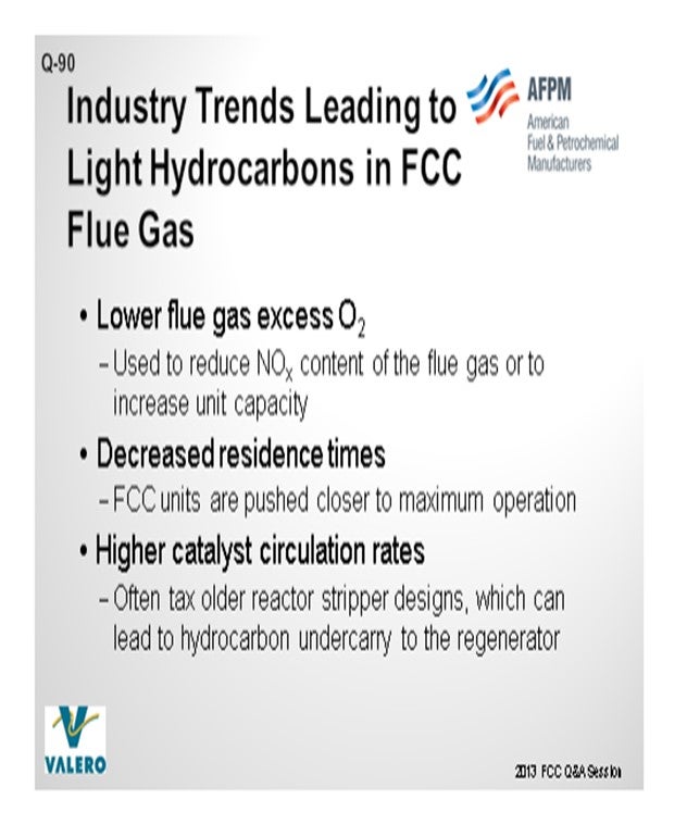
Some light hydrocarbons can be found in the flue gas in very small quantities, depending on the unit. The factors that contribute to light hydrocarbons in the flue gas are poor stripping in the reactor and maldistribution of the spent catalyst and very high catalyst circulation rates. Several industry trends have pushed the FCC units to operate in these undesirable regimes. Lower flue gas oxygen concentrations used to reduce NOx content of the flue gas or increase unit capacity have contributed to these materials being in the flue gas portion of the system. In the past, higher excess oxygen often masked distribution issues in regenerators that were not mixed well. Resonance times have decreased as FCC units have gone closer to their maximum mechanical operation, which has increased the superficial velocity of the regenerator in the flue gas system. Higher catalyst circulation rates often tax older reactor stripper designs, which can lead to hydrocarbon undercarry to the regenerator.
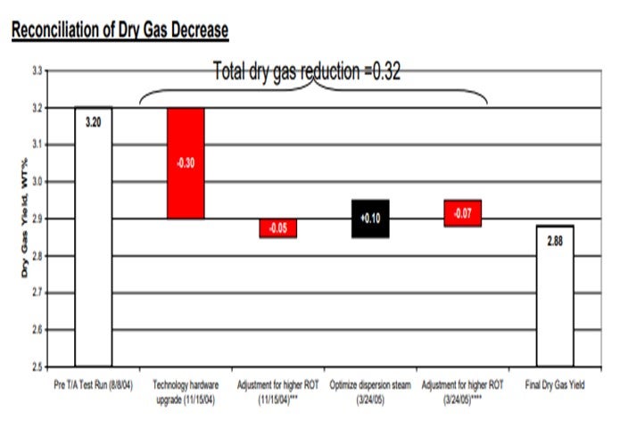
We have experience with an R2R first-stage regenerator where we installed a new CO boiler on the first-stage flue gas line; and when we calculated the efficiency of the burners, we were getting numbers at or above 100%. After thoroughly analyzing the flue gas, we found several peaks which had not previously been taken into account by the laboratory. These peaks turned out to be light hydrocarbons. When we adjusted the efficiency calculations to take into account the additional light hydrocarbon from the flue gas, we found that the efficiency came in at around 85%, which is what we had anticipated. We revalidated this finding when we installed the CONOx system on the same line. It consumed twice as much oxygen as we had anticipated for the same result on NOx reduction. We attributed the higher consumption to the light hydrocarbons. Now we believe a lot of this is not really due to the original licensor at all, but rather some installation of a spent catalyst distributor that we later added onto this unit. I want to put that caveat in there.
GIM (Technip Stone & Webster)
There are two possible reasons for such phenomenon to occur. First is the source. Poor catalyst stripping will create the opportunity for these hydrocarbons to escape to the regenerator. For the actual hydrogen-rich molecules to escape to the regenerator, the hydrogen coke has to be quite high. Many of the cat crackers operate way beyond their original design capacity which, frankly, taxes the traditional disc-and-doughnut or baffle stripper. It can benefit a lot from a more modern pack stripper technology, which is quite circulation-independent with high flux tolerance.
The actual distribution of stripping steam has also come into play. For example, if you have a stripper with a spent catalyst standpipe, then using two half-steam rings would be better than one full ring to distribute the steam in the stripper. And depending on the residence time and temperature, the severity of the stripper could also result in new formation of these light hydrocarbons.
Now when these molecules actually do escape to the regenerator, as Jeff alluded, the distribution of the spent catalyst into the regenerator will play a big role, in terms of how it promotes these light hydrocarbons, in enabling them to escape to the dilute phase. There would be less flash if the spent catalyst was evenly distributed into the regenerator, which becomes especially problematic for those regenerators with a larger diameter.
ROBERT “BOB” LUDOLPH [Shell Global Solutions (US) Inc.]
The light hydrocarbon can be a carrier of NOx and SOx precursors. So, if you experience a step change increase in SOx or NOx, look at your stripper operation for any performance changes.
J.W. “BILL” WILSON (BP Products North America Inc.)
On the unit that runs in partial burn, we have seen that if you watch the calculated hydrogen on coke, as you change the amount of CO combustion that is going off, you will actually see a change in hydrogen and coke. Nothing else is affected. Whether the absolute number is right or wrong, the fact is that it is changing with no change in the stripping steam: not a really significant change in catalyst circulation rate, just a change in the amount of excess oxygen being put into the unit. In this case with the amount of oxygen or the air we are putting in the unit, the excess oxygen is still quite low. This is because we never get out of partial burn.
So, one of the things we think might be happening, and we are still investigating, is that we may actually be forming, under certain circumstances, some of these light hydrocarbons, especially methane, in there. Since methane does not show up in your normal flue gas analysis, the hydrogen that is involved in that methane is now lost from the calculation for hydrogen on coke.
JEFFREY BULL (Valero Energy Corporation)
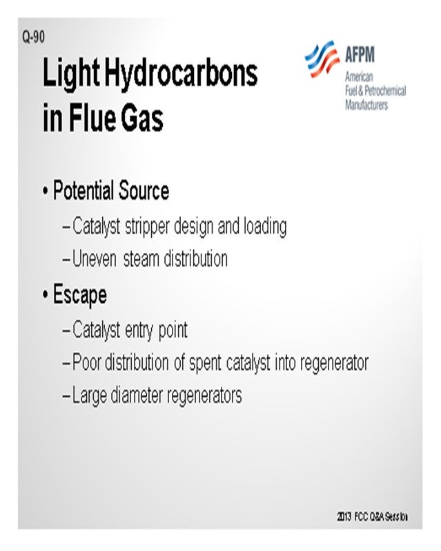
Some light hydrocarbons can be found in the flue gas in very small quantities, depending on the FCC unit. Poor stripping in the reactor, maldistribution of spent catalyst and air in the regenerator, and high catalyst circulation rates are all potential causes of hydrogen or light hydrocarbon in the flue gas. Several industry trends have pushed FCC units to operate in these undesirable regimes:
• Lower flue gas and excess oxygen used to reduce NOx content of the flue gas or to increase unit capacity has contributed to these materials in the flue gas portion of the system. In the past, higher excess oxygen often masked distribution issues in the regenerator.
• Residence times have decreased as FCC units are pushed closer to maximum operation, which increases the superficial velocity through the regenerator and flue gas systems.
• Higher catalyst circulation rates often tax older reactor stripper designs, which can lead to hydrocarbon under carry to the regenerator.
We have experience with an R2R first-stage regenerator where we installed a new CO boiler on the first-stage flue gas line; and when we calculated the efficiency of the burners, we were getting numbers at or above 100%. After thoroughly analyzing the flue gas, we found several peaks that had previously not been accounted for by the laboratory. These peaks turned out to be light hydrocarbons. When we adjusted the efficiency calculations to take the additional light hydrocarbon from the flue gas into account, we found that the efficiency came in at around 85%, which is what we anticipated. We revalidated this finding when we installed the CONOx system on the same line. It consumed twice as much oxygen as we had anticipated for the same result on NOx reduction. We attributed this to the light hydrocarbons. We feel that some of this is due to a spent catalyst distributor that we installed several turnaround cycles ago outside the scope of the original licensor.
Light hydrocarbons in the regenerator flue gas have historically not affected unit operation and are primarily a concern from an environmental standpoint. Most of the actions that the industry is taking to lower emissions in the FCC flue gas would tend to lower the light hydrocarbon content in the regenerator flue gas as well.
STEVE GIM (Technip Stone & Webster)
There are two possible reasons such phenomenon can occur: source and escape.
Source:
Poor catalyst stripping will let these hydrocarbons have a chance to escape to the regenerator. For actual hydrogen molecules to escape to the regenerator, the “hydrogen on coke” must be quite substantial. Many cat crackers operate way beyond their original design capacity, and traditional baffle or disc and donut designs can greatly benefit from modern packed stripper technology, which is really cat circulation-independent with its high flux tolerance. Distribution of steam is also important in the efficiency of stripper. For example, for strippers with a side spent catalyst standpipe, two half-steam rings are better than one full ring. You want both sides to have less potential for bypassing and the same residence time. You could be wasting steam on one side. Depending on the residence time and temperature, the severity of stripper can result in new formation of these molecules in the stripper.
Escape:
Poor catalyst distribution into the regenerator allows these light hydrocarbon escapees to continue their journey to the dilute phase. There will be less flash if spent catalyst is evenly distributed into the dense phase. This is especially problematic for regenerators with large diameters or catalyst entry is not optimal for introduction of the spent catalyst into the combustion sites.
JACK WILCOX (Albemarle Corporation)
Entrained un-stripped hydrocarbons resulting from inefficient or poor spent catalyst stripper operation are a common source of trace hydrocarbons in the regenerator flue gas. These entrained hydrocarbons are not burned due to maldistribution of the combustion air and/or spent catalyst allowing the light hydrocarbons to leave the regenerator with the flue gases. At the elevated flue gas temperature, and if there is, in fact, excess oxygen in the flue gas, the hydrocarbons will burn in the flue gas system potentially causing significant damage to the downstream equipment, particularly power recovery expanders, flue gas coolers, electrostatic precipitators, etc.
Year
2013
Process
Question 91: What FCC operating variables can be used to control the formation of acetone? What typical acetone concentrations are observed?
GIM (Technip Stone & Webster)
First of all, acetone is hard to detect by itself. It requires a special column in GC (gas chromatography) to pick up the polar species. Normal GC just picks up the regular hydrocarbons. We have seen acetone concentration in the C4 stream, butane and butylene (or BB, to be specific) as high as 800 ppm. In the same unit, we also measured average acetone concentration of 300 ppm over the course of the same month with values as low as 50 ppm. So, what are these sources of acetone? Oxygenates are byproducts of entrained oxygen in the regenerator and hydrocarbons in the reactor. Entrained oxygen from the regenerator to the reaction zone provides an opportunity for acetone formation in the reactor. Excess oxygen in the regenerator standpipe increases with higher catalyst circulation rate. High catalyst circulation rate entrains more air from the regenerator because the entrainments are among the catalyst particles.
Now, what are some of the potential ways to reduce this acetone formation? A few solutions for preventing acid formations are as follow:
1. Replace the instrument air in the reaction taps from air to nitrogen.
2. Tweak the operating variables may lead to some unnecessary increase in catalyst circulation rates such lowering the ROT (reactor outlet temperature), raise feed preheat, or use a higher activity and lower catalyst cooler duty, if you have them. Many of these will decrease the cat circulation rate and, therefore, the formation of the acetone.
3. Properly design the C3/C4 contaminant removal bed to help remove this acetone as well. Keep in mind that there may be other sources of oxygenates that had been introduced into the FCC system, such as external oxygenates or oxygenates that are being recycled, as well as some of the oxygenate-containing sludge in pipings.

BULL (Valero Energy Corporation)
We have seen levels of 50 to 200 ppm acetone in the BB stream in our refineries. Now for refiners in general, a move from 50 to 200 ppm is normally not that large; but if you are selling the stream as a chemical feedstock, the difference between the 50 and the 200 ppm can be significant on the downstream plants. That is definitely a consideration. Another concern about acetone in the feed to the alkylation unit is that it does result in higher acid consumption and can increase the ASO (acid-soluble oils) formation; but in low levels, this can normally be managed.
MICHAEL WARDINSKY (Phillips 66)
This question came up in 2007 when I was on the panel, and I remember answering it. You might want to consider making sure you have a good washwater rate going to your main frac overhead system because acetone should partition out to the sour water system when contacted with washwater.
MARTIN EVANS (Johnson Matthey INTERCAT, Inc.)
A question for Steve: You mentioned the use of contaminant removal beds to remove acetone. What type of beds are you suggesting?
GIM (Technip Stone & Webster)
We are talking about the activated alumina adsorbent bed.
STEVE GIM (Technip Stone & Webster)
Measuring Acetone: First, acetone is hard to detect by itself. It requires a special column in GC to pick up the polar species such as acetone, other oxygenates, and ECL. Normal GC just picks up regular hydrocarbons. We have seen acetone concentration in the C4 stream (butanes/butylenes or BB) as high as 800 ppm, but the same unit also measured acetone concentration averaged 300 ppm in daily measurements over the course of the same month, with values as low as 50ppm.
Source of Acetone: Oxygenates are byproducts of entrained oxygen and hydrocarbons. Entrained oxygen from regenerator to the reaction zone provides an opportunity for acetone formation in the reactor. O2 in the regenerated catalyst standpipe increases with higher catalyst circulation rate; higher catalyst circulation entrains more air from the regenerator because most of the entrainments are among the catalyst particles.
Reducing Acetone Formation: Some of the solutions for acetone are:
(1) replacement of instrument air on reaction taps from air to nitrogen.
(2) tweaking of operating variables that may result in an unnecessary increase in catalyst circulation rates such as lower ROT, higher feed pre-heat, higher catalyst activity, and lower catalyst duty; and,
(3) properly designing C3/C4 contaminant removal bed (such as activated alumina adsorbents).
It is also important be keep aware of potential other sources [of?] oxygenates that get introduced to the system including external oxygenates, oxygenates that are being recycled, and oxygenate containing sludge in pipings.
JEFFREY BULL (Valero Energy Corporation)
Ketone formation in the FCC is heavily dependent on the amount of air entrained from the regenerator into the reactor through the regenerated catalyst. As catalyst circulation is increased, more air is entrained and the formation of ketones will increase; so any operating variable that raises catalyst circulation can contribute to the formation of acetone. Specifically, reactor temperature, catalyst formulation, and stripping steam all have a strong correlation to catalyst circulation. Valero does not have much data on concentrations of acetone in the LPG product, but we have seen it in the 50 to 200 ppm range. We had a recent experience with not being able to sell some of our LPG product due to high acetone numbers. For refiners, the change in acetone formation from 50 to 200 ppm usually will have no effect on product quality. However, if the LPG is being sold as a chemical feedstock, this shift in concentration can adversely affect the downstream chemical plant. Acetone in the feed to the alkylation unit does result in higher acid consumption and increased acid soluble oil (ASO) formation; but in low levels, this can be managed. I will also refer you to the 2007 NPRA FCC Q&A response to Question 14 for further information on this topic.
JACK WILCOX (Albemarle Corporation)
Oxygen entrained in the circulating catalyst resulting from excessive instrument and standpipe aeration using air as a source, as well as excessive excess combustion air for catalyst regeneration, can provide the oxygen necessary for the generation of acetone. Instrument tap and standpipe aeration air rates should be properly controlled by utilizing appropriately sized restriction orifices in these locations. If possible, the aeration media should be changed to sweet fuel gas or nitrogen. Excess flue gas oxygen levels should be optimized to maintain the desired level of carbon on regenerated catalyst and carbon monoxide in the flue gas. Acetone is formed from the reaction between propylene and benzene plus oxygen. Avoid, if possible, charging extraneous streams to the vapor recovery unit containing cumene which reacts with oxygen to form acetone. High FCC reactor temperature will produce more propylene and benzene, the combination of which can react to produce cumene. The use of ZSM-5 additive will obviously produce higher levels of propylene as well. Units operating at elevated cracking temperatures to maximize light olefin will see acetone levels in the debutanizer overhead C3 + C4 stream as high as 1500 ppm. Acetone levels in the range of about 100 to about 1200 ppm have been observed in the C4 fraction.
Year
2013
Process
