Question 90: Regenerator flue gas often contains hydrogen and/or light hydrocarbons, even in the presence of excess oxygen. What are the likely sources of these materials? What are the implications of operating under these conditions?
BULL (Valero Energy Corporation)
Some light hydrocarbons can be found in the flue gas in very small quantities, depending on the unit. The factors that contribute to light hydrocarbons in the flue gas are poor stripping in the reactor and maldistribution of the spent catalyst and very high catalyst circulation rates. Several industry trends have pushed the FCC units to operate in these undesirable regimes. Lower flue gas oxygen concentrations used to reduce NOx content of the flue gas or increase unit capacity have contributed to these materials being in the flue gas portion of the system. In the past, higher excess oxygen often masked distribution issues in regenerators that were not mixed well. Resonance times have decreased as FCC units have gone closer to their maximum mechanical operation, which has increased the superficial velocity of the regenerator in the flue gas system. Higher catalyst circulation rates often tax older reactor stripper designs, which can lead to hydrocarbon undercarry to the regenerator.
We have experience with an R2R first-stage regenerator where we installed a new CO boiler on the first-stage flue gas line; and when we calculated the efficiency of the burners, we were getting numbers at or above 100%. After thoroughly analyzing the flue gas, we found several peaks which had not previously been taken into account by the laboratory. These peaks turned out to be light hydrocarbons. When we adjusted the efficiency calculations to take into account the additional light hydrocarbon from the flue gas, we found that the efficiency came in at around 85%, which is what we had anticipated. We revalidated this finding when we installed the CONOx system on the same line. It consumed twice as much oxygen as we had anticipated for the same result on NOx reduction. We attributed the higher consumption to the light hydrocarbons. Now we believe a lot of this is not really due to the original licensor at all, but rather some installation of a spent catalyst distributor that we later added onto this unit. I want to put that caveat in there.
GIM (Technip Stone & Webster)
There are two possible reasons for such phenomenon to occur. First is the source. Poor catalyst stripping will create the opportunity for these hydrocarbons to escape to the regenerator. For the actual hydrogen-rich molecules to escape to the regenerator, the hydrogen coke has to be quite high. Many of the cat crackers operate way beyond their original design capacity which, frankly, taxes the traditional disc-and-doughnut or baffle stripper. It can benefit a lot from a more modern pack stripper technology, which is quite circulation-independent with high flux tolerance.
The actual distribution of stripping steam has also come into play. For example, if you have a stripper with a spent catalyst standpipe, then using two half-steam rings would be better than one full ring to distribute the steam in the stripper. And depending on the residence time and temperature, the severity of the stripper could also result in new formation of these light hydrocarbons.
Now when these molecules actually do escape to the regenerator, as Jeff alluded, the distribution of the spent catalyst into the regenerator will play a big role, in terms of how it promotes these light hydrocarbons, in enabling them to escape to the dilute phase. There would be less flash if the spent catalyst was evenly distributed into the regenerator, which becomes especially problematic for those regenerators with a larger diameter.
ROBERT “BOB” LUDOLPH [Shell Global Solutions (US) Inc.]
The light hydrocarbon can be a carrier of NOx and SOx precursors. So, if you experience a step change increase in SOx or NOx, look at your stripper operation for any performance changes.
J.W. “BILL” WILSON (BP Products North America Inc.)
On the unit that runs in partial burn, we have seen that if you watch the calculated hydrogen on coke, as you change the amount of CO combustion that is going off, you will actually see a change in hydrogen and coke. Nothing else is affected. Whether the absolute number is right or wrong, the fact is that it is changing with no change in the stripping steam: not a really significant change in catalyst circulation rate, just a change in the amount of excess oxygen being put into the unit. In this case with the amount of oxygen or the air we are putting in the unit, the excess oxygen is still quite low. This is because we never get out of partial burn.
So, one of the things we think might be happening, and we are still investigating, is that we may actually be forming, under certain circumstances, some of these light hydrocarbons, especially methane, in there. Since methane does not show up in your normal flue gas analysis, the hydrogen that is involved in that methane is now lost from the calculation for hydrogen on coke.
JEFFREY BULL (Valero Energy Corporation)
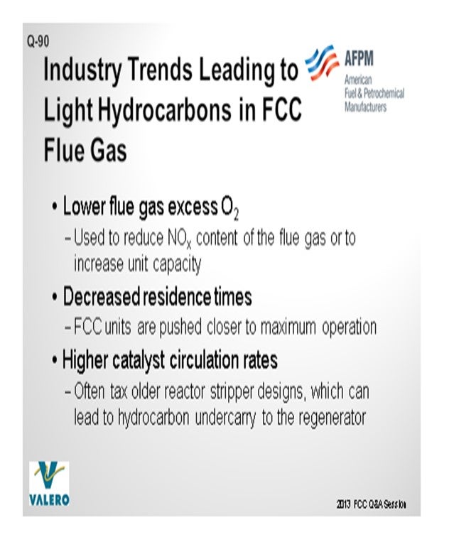
Some light hydrocarbons can be found in the flue gas in very small quantities, depending on the FCC unit. Poor stripping in the reactor, maldistribution of spent catalyst and air in the regenerator, and high catalyst circulation rates are all potential causes of hydrogen or light hydrocarbon in the flue gas. Several industry trends have pushed FCC units to operate in these undesirable regimes:
• Lower flue gas and excess oxygen used to reduce NOx content of the flue gas or to increase unit capacity has contributed to these materials in the flue gas portion of the system. In the past, higher excess oxygen often masked distribution issues in the regenerator.
• Residence times have decreased as FCC units are pushed closer to maximum operation, which increases the superficial velocity through the regenerator and flue gas systems.
• Higher catalyst circulation rates often tax older reactor stripper designs, which can lead to hydrocarbon under carry to the regenerator.
We have experience with an R2R first-stage regenerator where we installed a new CO boiler on the first-stage flue gas line; and when we calculated the efficiency of the burners, we were getting numbers at or above 100%. After thoroughly analyzing the flue gas, we found several peaks that had previously not been accounted for by the laboratory. These peaks turned out to be light hydrocarbons. When we adjusted the efficiency calculations to take the additional light hydrocarbon from the flue gas into account, we found that the efficiency came in at around 85%, which is what we anticipated. We revalidated this finding when we installed the CONOx system on the same line. It consumed twice as much oxygen as we had anticipated for the same result on NOx reduction. We attributed this to the light hydrocarbons. We feel that some of this is due to a spent catalyst distributor that we installed several turnaround cycles ago outside the scope of the original licensor.
Light hydrocarbons in the regenerator flue gas have historically not affected unit operation and are primarily a concern from an environmental standpoint. Most of the actions that the industry is taking to lower emissions in the FCC flue gas would tend to lower the light hydrocarbon content in the regenerator flue gas as well.
STEVE GIM (Technip Stone & Webster)
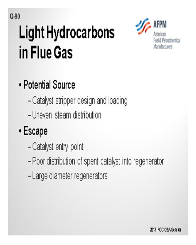
There are two possible reasons such phenomenon can occur: source and escape.
Source:
Poor catalyst stripping will let these hydrocarbons have a chance to escape to the regenerator. For actual hydrogen molecules to escape to the regenerator, the “hydrogen on coke” must be quite substantial. Many cat crackers operate way beyond their original design capacity, and traditional baffle or disc and donut designs can greatly benefit from modern packed stripper technology, which is really cat circulation-independent with its high flux tolerance. Distribution of steam is also important in the efficiency of stripper. For example, for strippers with a side spent catalyst standpipe, two half-steam rings are better than one full ring. You want both sides to have less potential for bypassing and the same residence time. You could be wasting steam on one side. Depending on the residence time and temperature, the severity of stripper can result in new formation of these molecules in the stripper.
Escape:
Poor catalyst distribution into the regenerator allows these light hydrocarbon escapees to continue their journey to the dilute phase. There will be less flash if spent catalyst is evenly distributed into the dense phase. This is especially problematic for regenerators with large diameters or catalyst entry is not optimal for introduction of the spent catalyst into the combustion sites.
JACK WILCOX (Albemarle Corporation)
Entrained un-stripped hydrocarbons resulting from inefficient or poor spent catalyst stripper operation are a common source of trace hydrocarbons in the regenerator flue gas. These entrained hydrocarbons are not burned due to maldistribution of the combustion air and/or spent catalyst allowing the light hydrocarbons to leave the regenerator with the flue gases. At the elevated flue gas temperature, and if there is, in fact, excess oxygen in the flue gas, the hydrocarbons will burn in the flue gas system potentially causing significant damage to the downstream equipment, particularly power recovery expanders, flue gas coolers, electrostatic precipitators, etc.