
Question 1: What is a typical hydrofluoric (HF) acid inventory (pound of acid per bpdC5+ alkylate), and what steps are refiners considering reducing this volume? What other risk mitigation steps are refiners considering for their HF units?
BULLEN (UOP LLC, A Honeywell Company)
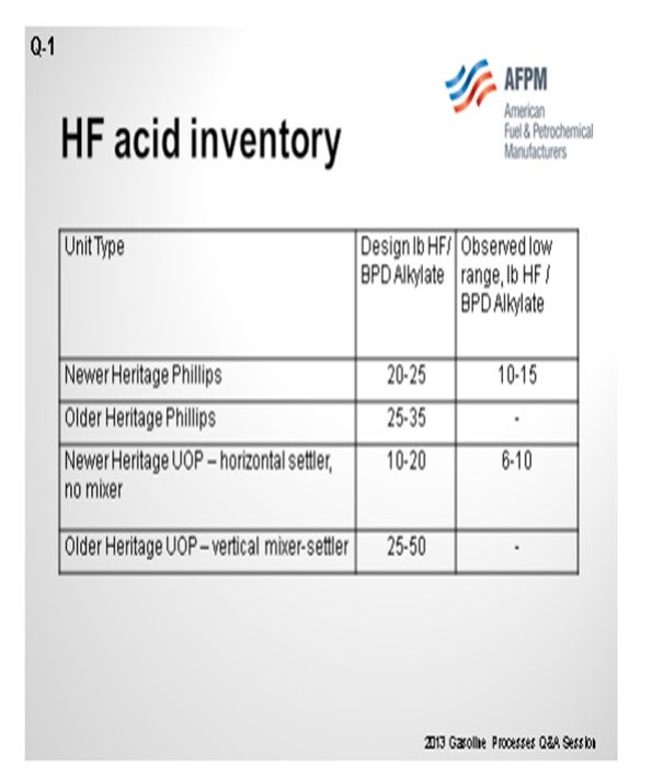
As you can see on the slide, there is a big variation in the design HF-to-alkylate ratios. The order of older units, as denoted by old Heritage-Phillips and old Heritage-UOP types, has fairly high ratios. The more modern ones were designed with lower ratios. The actual observed ratios are even less than that. A lot of this depends on whether units have been revamped. If they have a higher throughput, then the ratio will reduce further. If you have an old-designed UOP vertical mixer settler, you can take advantage of reducing the ratio by eliminating that mixer and then just having the settler. However, you will increase your organic fluorides and your product streams approximately two times. There are some other things in the design that you can do to help reduce it down further.
Regarding risk mitigation steps, if you follow the mitigation options in the API (American Petroleum Institute) 751, you can reduce your risk. Some of these include utilizing acid leak detection systems, water spray mitigation systems, rapid acid inventory systems, remotely operated isolation valves, and passive mitigation systems. You can find more details in my Answer Book response to this question.
MELDRUM (Phillips 66)
Phillips 66 has seven operating HF alkylation units. Based on these units, our average acid inventory is 16 pounds per barrel of alkylate. The range is from 11 to 20 pounds of acid per barrel of alkylate. Our UOP pumped acid unit is on the low end of that range.
Inventory minimization is accomplished principally through two areas. One is process design. The older units were designed with a riser of about 50 feet. Newer designs have risers of about 30 feet. The shorter riser then equates to a lower settler level. The reduction in this riser height also reduces the acid-to-hydrocarbon ratio from 4:1 to about 3.5:1. The second way that acid in the unit is minimized is through limiting the stored fresh acid inventory. In my Answer Book response, I have provided some of the risk management methods grouped in the areas of prevention, detection, and mitigation.
PATRICK BULLEN (UOP LLC, A Honeywell Company)
The acid inventories of the HF alkylation units in operation vary significantly and depend on the type of reactor section design and the actual operating isobutane-to-olefin (I/O) ratio. Lower I/O ratio allows higher alkylate throughput in a given unit, which reduces acid inventory when measured in pound of HF/bpd (barrel per day) alkylate. The table below indicates the ratio range of various types of HF alkylation units.
Proper control of the acid settler level, maintaining sufficient level to prevent hydrocarbon carry under into the circulating acid stream can minimize the acid inventory in any given design. Reliable level indication in the settler helps to achieve good acid level control. Also, good coordination between the refiner and acid supplier to deliver acid at the right time will prevent excessive acid inventory in the acid storage drum. Elimination of the 20-tray mixing section from the vertical mixer-settlers in the older Heritage-UOP design units can be the biggest step toward inventory reduction. Eliminating the mixing section has been done at several units. The downside of eliminating the mixing section is that the number of organic fluorides in the product streams (propane, n-butane, and alkylate) approximately doubles.
Depending on the specific unit design, there may be other design changes that can be made to achieve relatively smaller reductions in acid inventory.
There is a good summary of the various risk mitigation options in Section 6 and Appendix H of the new 4th Edition of API RP 751 which was released in May 2013. In general, the basic risk mitigation options are:
• acid leak detection (which includes sensors, cameras, and flange paint),
• water spray mitigation systems,
• rapid acid de-inventory systems,
• remotely-operated isolation valves, and
• passive mitigation systems (such as barriers, acid inventory control, and vapor suppression additives).
Continuous acid leak detection and remotely operated and controlled water spray mitigation are generally considered to be requirements in an HF alkylation unit.
CRAIG MELDRUM (Phillips 66)
A Quantitative Risk Assessment (QRA) study can give valuable information on the benefits of reducing acid inventory compared to other mitigation options. Risk management is based on prevention, detection and mitigation.
• Prevention: proper equipment design (including management of change for equipment or process changes), routine maintenance, effective inspection, well trained and disciplined operators and maintenance, and ongoing risk assessments studies and corrective action
• Detection: rapid and reliable HF detection (point and/or open path), HC detection as a surrogate for HF, visual detection (camera and acid detection paint), and alert personnel (operations, maintenance, technical, and management)
• Mitigation: isolation valves, acid transfer, water spray, barriers (used principally by one operating company), and modified acid additive (limited use in the industry)
Year
2013
Process
Question 2: Have seal-less pumps (magnetic drive or canned pumps) been used successfully in HF and sulfuric acid alkylation units? What services are considered for this equipment?
MELDRUM (Phillips 66)
Yes, sealless pumps have been successfully used in both HF and sulfuric alkylation processes, typically in the acid rerun system for the HF process and fresh acid service for the sulfuric process. However, the API-610 sealed pump is, by far, the most commonly used pump based on the fact that API 610 pumps are familiar within the refinery for the Maintenance and Projects groups and also because of their robust design and relatively low initial cost.
As I reviewed some of Phillips’ process design specifications, I found a statement referring to both magnetic drive and canned pumps: “We do not have enough experience with this type of pump to recommend features and styles.” It was also mentioned in the specification: “Because of the slightly magnetic nature of nickel copper alloys, the containment shell of the mag-drive pump for HF service should be Hastelloy C-276.”
The interest in sealless pumps is due to the lower risk from potential seal leaks. However, it is now quite common practice to use dual seals for acid service. Also, the seal reliability has improved over the years. Therefore, the risk of a sealed pump in HF acid service, in particular, has been reduced. One risk consultant stated that the limited history on sealless pumps in HF acid service results in his refinery using the same failure rate as that of a dual-sealed pump when they conduct their quantitative risk assessment studies. What I have concluded is that when considering sealless pumps for new construction or major equipment replacements, you should work with a risk consultant to determine if the sealless pump is effective at achieving your risk management objectives. I have also provided, in my Answer Book response, several considerations to review as you look at selecting a pump for HF acid service.
BULLEN (UOP LLC, A Honeywell Company)
UOP has limited experience with sealless pumps in HF units. The one concern we have is that these types of pumps are different than most of the other pumps in the refinery; so, you really need to have Operations and Maintenance crews who are experienced dealing with this type of pump. A lot of human error can creep in and cause the pumps to fail. The experience we have had has been in relatively small-sized applications such as the acid rerun feed pump. One of our customers in Europe has actually been successfully using three pumps in circulating acid, settled acid, and isostripper reflux operations since 1994. So, it is possible to have a long run with these types of pumps. Also, sealless pumps tend to not meet requirements for API standards; they are ASME (American Society of Mechanical Engineers) standard type pumps; so that can be an issue. As Craig said, dual seals have gotten a lot better in the past 20 years and become more reliable; so, it is questionable whether you are actually safer with the sealless system, in terms of reliability and leaks.
ROBERTSON (AFPM)
Does anyone else in the audience have experience with sealless pumps?
CHRIS GREEN (Marathon Petroleum Corporation)
I work at the Galveston Bay Refinery. We use the mag drive style pump on the rerun to our feed. We had previously experienced a bolting failure on the conventional style pump and the case opened up. We had good reliability. We have been using them since about 2003, and they have proven to be reliable in that service.
CRAIG MELDRUM (Phillips 66)
Some consideration for HF acid pump selection:
• Service Conditions: Temperature (mag-drive pumps limited to ~350°F, canned pumps can take up to 1000°F) and solids content of the pumped fluid (sealless pumps can be more sensitive to solids in the fluid)
• Durability: Operation under upset conditions or from poor operations such as dead-headed and run dry
• Cost: Initial pump cost plus the seal cost plus ongoing maintenance costs. Sealed pumps will likely have a lower initial cost, but long-term seal maintenance costs may favor sealless pumps.
• Alignment and Foundation Requirements: Pump-to-driver alignment and foundation requirements are minimal for canned pumps.
• Containment against Catastrophic Failure: Canned pumps have secondary containment by design.
• Failure Scenarios and Mitigation: Sealed pumps are most likely to fail at the seal; sealless pumps are most likely to fail at the bearing.
• Maintenance: Onsite knowledge for repairs versus factory service and spare parts inventory needs
• Technical Support: Factory support to assist in working through any ongoing issues
PATRICK BULLEN (UOP LLC, A Honeywell Company)
There are two basic types of sealless pumps: magnetic drive and canned motor. UOP has limited experience with both types in HF alky units. In general, UOP’s experience is that the magnetic drive and canned motor pumps can work in HF alkylation service, but they are sufficiently different from standard single-stage process pumps that require special design considerations, maintenance, and operating procedures for successful operation. UOP is aware of several cases where a refiner installed a sealless pump and experienced serious damage to that pump within a very short time due to issues such as incorrect operating procedures or insufficient spillback or flush supply. This type of damage to a sealless pump is typically VERY expensive to fix and typically requires shipment of the pump back to the manufacturer, causing the pump to be out of service for several weeks.
Most of the sealless pumps used in HF alkylation units have been relatively small sized pumps. One specific service where a few refiners have used a sealless pump is the acid rerun column feed pump.
One UOP licensed unit in Europe has had good experience with canned pumps in HF service. This refiner installed three canned pumps in 1994, and those pumps are still used today. The specific pump services are circulating acid, settled acid, and isostripper reflux. This same refiner had negative experience with a magnetic drive pump in isostripper reflux service. This refiner uses sealless pumps in other applications in the refinery such as FCC sour water.
Another licensee in Europe uses magnetic drive pumps in two very large flow services. One is the acid circulation pump, and the other is the isostripper feed pump. The experience has been good with both of these pumps. These pumps receive special mechanical attention and service, which are probably keys to their successful performance.
It is worth noting that some of these sealless pumps are not built to be compliant with all of the requirements of the API standard for refinery service pumps. Instead, they are built to ASME standards that are used predominantly in the chemical industry.
Many refiners have chosen dual seals over sealless pumps because the reliability of dual seals in acid service has improved significantly over the past 20 years or so. In addition, the dual seals have a lower cost to install on existing pumps, and the maintenance and operation of the dual seals is typically well-understood by the refinery staff.
Year
2013
Process
Question 3: What drives the decision to load presulfided, presulfurized, or oxidized catalyst in naphtha hydrotreaters? What are the different safety considerations for each case?
MELDRUM (Phillips 66)
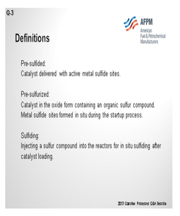
I would like to begin my responses by grounding us in some definitions. Pre-sulfided catalyst is the catalyst that is delivered with an active metal sulfide site. Pre-sulfurized catalyst is catalyst in the oxide form but which then has added to it an organic sulfur compound. The metal sulfide sites are then formed in-situ during the startup process. Finally, sulfiding is the process of injecting a sulfur compound into the reactor for in-situ sulfiding after the catalyst is loaded.
At Phillips 66, we use pre-sulfided catalyst in naphtha units when there is no off-test product line or tankage or where we want to save our startup time. We plan for about one to two days to complete an in-situ sulfiding step which can be eliminated using the pre-sulfided catalyst. We will also use pre-sulfided catalyst if we skim and replace a portion of a catalyst bed. If we are skimming more than 20 to 25% of the bed, we will come in with the pre-sulfided catalyst. If we are only skimming and replacing about 15% of the bed, then non-sulfided catalyst will be used; so there will be no need to do a separate sulfiding step during startup.
We generally do not use pre-sulfurized catalyst in naphtha service based on a slight concern about how the passivating agent might come off causing a sulfur slip to the reformer. This is not a major issue, but it might impact the downstream reformer for a couple of days.
Most of our naphtha high-treating catalysts are loaded in the oxide form and then sulfided in-situ as part of the startup process. When we do use pre-sulfided or pre-sulfurized catalysts, we make it a practice to order some of the inventory in the oxide form so that it can be returned if it is deemed surplus material. Once the catalyst has been sulfided or treated with the sulfurization chemical, then any surplus catalyst will be difficult to return. As precaution, we load sulfided and pre-sulfurized catalysts under inert conditions to prevent self-heating. We also use respiratory protection, usually supplied air, regardless of the catalyst condition to protect against any of the dust.
STREIT (KBC Advanced Technologies, Inc.)
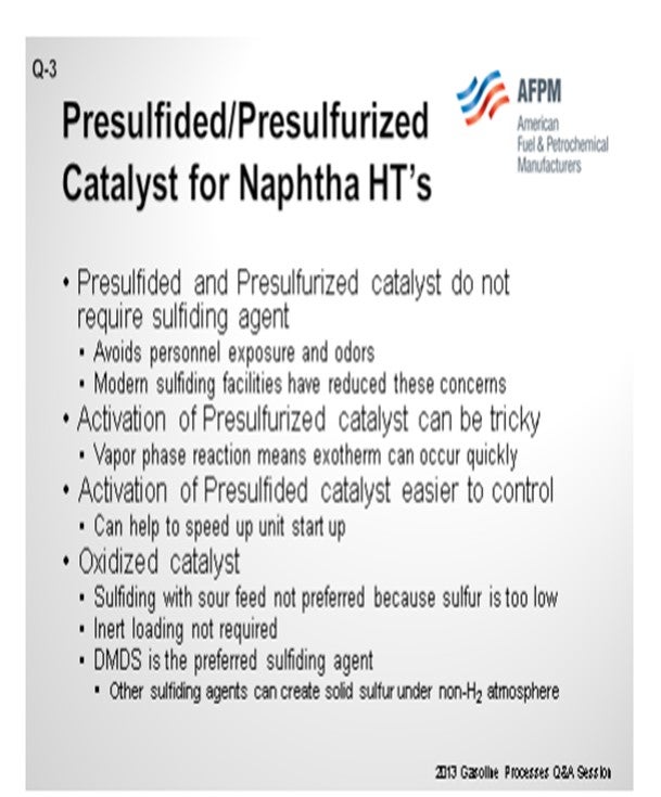
I will mostly confirm what Craig just said. Pre-sulfided and pre-sulfurized catalysts do not require sulfiding agents. That is really one of the drivers for why you might want to purchase that material. Also, it avoids personal exposure and odors. It is less of a problem than it was in the past with the modern injection facilities and sulfiding agents, but still a concern.
Pre-sulfurized catalyst: One point that should be noted on a naphtha unit is that because of the vapor phase and the reaction, you can end up with some temperature issues when you are activating it. So be a little wary of this when using pre-sulfurized catalyst in this service. The activation of pre-sulfided catalyst is a lot easier to control, and the typical driver is just startup time. You can get the unit up a lot more quickly.
Oxidized Catalyst: If you decide to go with oxidized catalyst and have to go through the sulfiding step, then you will need to use some solid sulfurizing agent. In other services, you could use the feed sulfur to sulfurize a catalyst. In naphtha service, that is usually not high enough to be the case. The advantage of oxided catalyst is that you do not need inert loading facilities.
ERIC STREIT (KBC Advanced Technologies, Inc.)
Sulfiding with sour feed is usually not preferred in naphtha hydrotreaters because the low feed sulfur results in an H2S partial pressure too low to adequately activate the catalyst. So, the catalyst does need to be sulfided in some way.
If oxidized catalyst is used, the refiner must use a stream with a high H2S content or add a sulfiding agent of some type to activate the catalyst. DMDS (dimethyl disulfide) is the best sulfiding agent for this service. Other sulfiding agents, like polysulfides, have the potential to produce solid sulfur when no hydrogen is present. There are concerns with personnel exposure and odors with any sulfiding agent. Many refiners choose to avoid these issues by ordering catalyst with the sulfur already on the catalyst. With modern injection systems, leakage of sulfiding agents is usually a minor issue.
Presulfurized catalyst, where the sulfur has added to the catalyst but has not been activated, can cause problems in naphtha hydrotreater service. Because the reactions are occurring in the vapor phase, temperature control during the sulfiding step can be difficult, and the operator may experience a temperature excursion that could damage the catalyst. This is exacerbated by the fact that most naphtha hydrotreaters do not have bed thermocouples, so it is particularly difficult to control the heat release.
Adding presulfurized catalyst as makeup from a reactor skim can usually be done without major problems. In this case, only a small portion of the bed is being replaced; so, the exotherm during activation is not great. Loading presulfided catalyst, where the catalyst has been fully sulfided and activated by the supplier, provides the fastest way to bring the unit online. Presulfided catalyst is more expensive but can be justified in some instances. Examples of where presulfided catalyst may be justified include 1) units where pre-heat is limited and proper activation temperatures are hard to reach and 2) units where a fast startup is required, such as when the only hydrogen source in the refinery is the reformer.
Using catalyst with sulfur already on it should be done in an inert environment. Loading oxidized catalyst does not require an inert atmosphere, so operators who want to avoid loading under these conditions should choose oxidized catalyst.
STEVE TREESE (Phillips 66)
The following are a few definitions to establish a foundation for the answer.
• Presulfided: Catalyst manufactured and delivered with active metal sulfide sites on the catalyst.
• Presulfurized: Catalyst in the oxide form that has an organic sulfur compound added in the manufacturing step then passivated with a heavy organic material. Sulfiding occurs in-situ as part of the startup process, but the sulfur compound does not need to be injected onsite.
• Sulfiding: The process of injecting a sulfur compound into the reactors after catalyst loading for in-situ sulfiding as part of the startup process.
We use presulfided catalyst in naphtha units where there is no off-spec product line or tankage or where we need to save startup time (one to two days to sulfide in-situ). We also use it if we have skimmed and replaced more than about 20 to 25% of the bed (~15% of the bed can be skimmed and replaced with non-sulfided catalyst and without sulfiding as a separate startup step). The presulfided catalyst is handled under inert conditions as a precaution.
We generally do not used presulfurized catalyst in naphtha services based on slight concerns over the heavy, high endpoint passivation material going to the reformer and the amount of sulfur slip to the reformer. This is not a big issue, but it may hit the reformer for a couple of days. Most of our naphtha hydrotreating catalysts are loaded in the oxide form and then sulfided in-situ as part of the startup process.
When presulfided or presulfurized catalyst is used, we order some of the catalyst in the oxide form so it can be returned if there is surplus material. Once catalyst has been sulfided or loaded with sulfurization chemicals, then any surplus catalyst will be difficult to return. +
For presulfided and presulfurized catalysts in any service, we load under inert conditions to prevent self-heating. In theory, the catalysts are often passivated so they can be handled in air, but we are concerned about how long that protection lasts (one to two days) compared to how long it takes to load the beds (should be one to two days; but if delayed, it could be three to four days). In all cases, respiratory protection (usually supplied air) is used, regardless of the catalyst condition to protect against the dust
Year
2013
Process
Question 4: Is there any experience producing on-specification jet fuel without any sulfur/mercaptan treating, including any form of caustic, from feedstocks produced from ‘tight’ formations? What other jet specifications are adversely impacted by the changed feedstock?
STREIT (KBC Advanced Technologies, Inc.)
The main idea here is that there is no real change to the way you make jet fuel based on tight oil. There may be slight changes to the freeze point due to the paraffinicity of the tight oil, but that is actually just dependent on the tight oil itself. If that is the case, really all that is required is a cutpoint adjustment in the crude unit to get on-spec on the freeze. You normally have to do some sort of treating through a clay treater in order to get on-spec for JFTOT (Jet Fuel Thermal Oxidation Test) and WSIM (Water Separation Index Modified), but that is not really different with tight oil versus conventional oil. You do not strictly have to treat for sulfur/mercaptan to make jet fuel, but most places like to do some sort of treating as a safety net to make sure that the final product is on-spec, particularly on mercaptan.
GROPP (GE Water & Process Technologies)
In support of what Eric said, we are not aware of anyone consistently producing on-specification jet fuel without some type of processing or treatment to address sulfur compounds including H2S, mercaptans, and thiophenols. Typically, we see refiners using hydrotreating and/or caustic extraction processes to remove these trace contaminants. It only takes a small amount of sulfur in the right form to throw the fuel off specification. Without removing the contaminants, refiners can expect to fail the JFTOT, as well as the Copper Strip Corrosion and Mercaptan or Doctor tests. In addition, without treatment, the fuel may not pass acidity specifications.
TERRY HIGGINS (Hart Energy Research and Consulting)
Regarding the freeze point, I would have thought that freeze point would be more of an issue for people who are running a large amount of Eagle Ford crude. I think you indicated that it was not too much of an issue, just a small cutpoint. Are you familiar with situations where there were large volumes of the tight oils that would have been difficult to make at all, in terms of having a strong impact on that freeze point?
STREIT (KBC Advanced Technologies, Inc.)
I am not personally aware of any particular issue with that situation. It is more of an assumption based on the presumed paraffinicity of the tight oils, which may or may not be true, depending on the specific tight oil we are discussing. I would be very interested to hear if anyone else has any issues with that. R.E. “ED” PALMER (Wood Group Mustang, Inc.) I know that in some designs we are doing on these condensate splitters, where we are making distillates, that distillation cutpoint is limited by the freeze point of the product.
RONALD GROPP (GE Water & Process Technologies)
We are not aware of any finished, on-specification jet fuel produced without some sort of processing to remove sulfur and/or sulfur compounds including H2S (hydrogen sulfide), mercaptans (thiols), and thiophenols. Typically, we see caustic extraction and/or sweetening processes or hydrotreating processes utilized to remove sulfur or change the sulfur compounds to less objectionable forms. If these sulfur contaminants are not addressed, the fuel will likely fail to meet specifications including Thermal Stability (ASTM D3241), Copper Corrosion (ASTM D130), Mercaptan Sulfur (ASTM D3227), and/or Doctor Tests (ASTM D4952-12). In addition, caustic treating or hydroprocessing methods may be required to meet Acidity (ASTM D3242) specifications.
ERIC STREIT (KBC Advanced Technologies, Inc.)
Virtually all jet fuel needs to be processed through a clay treater to ensure that the product meets JFTOT and WSIM specifications. Tight oil processing does not really change this requirement. Although there may be some freeze point differences due to the higher paraffinicity of some tight oils, this can be countered by changing the cutpoint upstream.
Jet fuel can be produced without treating for sulfur or mercaptans due to its high sulfur specification. Some refiners have had success doing this. However, operating with no treatment can be risky. To avoid the risk of producing off-spec jet, many refiners use some type of caustic treating or hydrotreating to ensure that they will not have problems with mercaptans. In any case, tight oil is lower in sulfur content than conventional oil; so, it should only help lower the jet fuel sulfur level. In cases where sulfur may be an issue and hydrotreating is not used, adjustments to upstream cutpoints can be made to marginally reduce sulfur.
Refiners producing jet fuel from tight oils should be aware that the jet fuel final boiling point may need to be decreased due to the freeze point. The economics of processing tight oil should consider this, and linear program cutpoints should be adjusted accordingly. However, it is unlikely that any adjustments to jet fuel final boiling points will influence whether or not to process tight oil.
Year
2013
Process
Question 5: Reforming of feedstocks from ‘tight oil’ crudes offers unique challenges such as low naphthene and aromatic (N+A) content, lighter feed, and differences in coke yield.What are refiners doing to address these challenges and generate opportunities for these new crudes?
BULLEN (UOP LLC, A Honeywell Company)
From a project standpoint, there have been inquiries related to tight oil and proposals generated, but not a significant number of actual projects realized for revamping units. It appears that most refiners are able to accommodate the tight oil in their existing units. Some of this accommodation has to do with the naphtha area capacity issues in the U.S. of which I am sure everyone is aware. There are opportunities to change the catalyst types to be a more active type and come up with a more coke-tolerant type catalyst to address the higher coke make you get with more paraffinic feeds.
MELDRUM (Phillips 66)
This whole subject of tight oils or shale oils is interesting. I am not sure there has been an event in the industry that has had as quick and broad of an acceptance as the bringing of tight oils to market. A typical operating company could probably anticipate seeing a doubling (or greater) of their use of tight oils over the next five years from where they are currently processing. Tight oils are typically more paraffinic and lighter than many of the current crude oils. As such, the naphtha cut being fed to the reformer unit from these oils will be leaner and have a lower naphthene and aromatics content. Additionally, the quantity of that cut will increase, which will impact the reformer in all areas of activity, selectivity, and stability, the extent of which depends upon the type and amount of the tight oil or shale crude that is processed.
One of our sites processes 20% of an Eagle Ford crude. They have experienced a 4 to 6- number drop in their naphtha feed quality as measured by the naphthene and aromatic content (N+2A). The process impact was a 1-number drop in the octane number that was offset by adding 4 to 6°F additional reactor temperature to hold the previous octane target. The associated yield decline has been about 1.5 liquid volume percent C5 plus. The coke make is expected to increase by about 10% due to the added severity on the unit. This would then have an associated shorter cycle life to the catalyst from regeneration to regeneration.
Another of our sites processing 35% of Bakken crude has seen a 5-number drop in its naphtha feed quality (N+2A), which has lowered the reformate octane. The additional naphtha from that processing, which is not able to fit into the reformer unit, bypasses the unit and goes directly to fuel blending.
STREIT (KBC Advanced Technologies, Inc.)
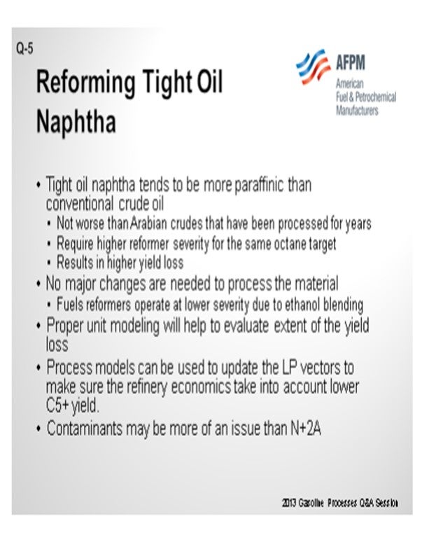
I do not have a lot to add, more of a confirmation. We alluded to it in the last question. We make some assumptions or generic statements about tight oil; but in fact, it is a rather broad spectrum. It does tend to be more paraffinic, but it is not, by definition, more paraffinic. It is not really worse than any of the Arabian crudes that have been processed through the years, as far as N+2A. Typically, it will be a little more paraffinic, which means you need a little more severity for the same octane target, as was stated before. This results in a slightly higher yield loss through the reformer; but in general, no major changes are needed to process this material. Because of ethanol blending and the corresponding lack of demand for octane from a reformer, most reformers in the United States now have the room to go up on severity. So, there is likely available capacity to make up for that additional severity that you need.
I want to point out that it is very possible that the LP (linear program) models, which are making the decisions on what kinds of crudes to buy and the economic value of those feedstocks, may not properly reflect the yield loss that you might see from a tight oil. So those LP vectors need to be updated to make sure the LP is up to speed to properly reflect that yield loss. The final point outside of the N+2A or the paraffinicity issue is that there seems to be a lot more contaminants which we have not seen in the past that are showing up, and those may be a larger concern than the actual N+2A or the reformer feed quality.
VICTOR TAILER (Commonwealth Engineering & Construction)
I have a general question. Since the quantity of tight oil processing is going to increase, how does this increase impact delayed coker units which operate at the low pressure, and how will the coker yields will change? How does tight oil processing impact the fractionator operation? Do they need any revamp, or is it done with any equipment modification?
MEL LARSON (KBC Advanced Technologies, Inc.)
If I understand the question correctly, you are asking about the impact of the tight oils that would go through the coker. The issue is going to be with the quantity. We would expect that quantity of material because there is not as much bottoms within 50-plus in the material. In general, for that material, if the Conradson carbon residue content is about the same, we would not expect the yield shift to be too much more dramatic or even the yield profile to be an issue. Most of what we have seen so far in the coking conferences I have attended are strictly hydraulic rate issues about the minimum feed rate. If those change, the coker distillate or coker naphthas will not be too much different than they are today, as far as their properties; only the mass rate will drop quite substantially.
JESUS CABELLO (Foster Wheeler USA Corporation)
What we have seen with some of the clients processing tight oils is some kind of incompatibility between tight oils and conventional oils that is creating issues in the heaters.
TERRY HIGGINS (Hart Energy Research and Consulting)
I have a quick comment on the crude N+A (naphthene plus aromatic content). One of the biggest impacts has to do with the crude oil you are backing out. For example, many people have had to back out Nigerian crude in order to accommodate the excess domestic light crudes. There you have a significant N+A shift. However, it is true that if you start backing out crude oil such as Arabian, you will not see that much difference.
PATRICK BULLEN (UOP LLC, A Honeywell Company)
Refiners are looking at potential options such as CCR (continuous circulation rate) Platforming™ process unit regeneration section revamps to increase coke burn capacity or even catalyst volume increases via reactor additions. Other options include catalyst changes to more active and more coke-tolerant catalysts.
The general activity for revamps is not particularly high for tight oil-related additions presently. Some of the potential reasons for this are the following:
a. Tight oil is difficult to define as the assays vary within the field and over time, depending on the recovery. This difficulty makes long-term predictions and economics harder to calculate. This, in turn, makes projects more difficult to justify.
b. Tight oil in the naphtha range is not too different from some paraffinic crudes, such as Saudi Light, so the general effects are known and can be put into existing systems that may be underloaded.
c. The volumes of tight oil are still growing and being established.
Contaminants vary in tight oil as well due to the unique processing to recover these oils. Combined nitrogen and olefin spikes have been noted by refiners. These types of contaminants tend to require severe hydrotreating similar to that required for coker naphthas.
ERIC STREIT (KBC Advanced Technologies, Inc.)
First of all, reformer feed from tight oil is not any worse than Arabian crudes, which many folks processed for a number of years without major issue. Tight oil naphtha does tend to be more paraffinic and, therefore, makes worse reformer feed than naphtha from most conventional crudes.
More paraffinic reformer feed means higher severity, higher coke makes, and lower hydrogen yield for the same octane. However, in the U.S. and elsewhere, there has been a big drop in reformer octane target (due to ethanol/oxygenates use) on units that are not making BTX (benzene, toluene, and xylene). As a result, there is likely room for handling the additional severity required due to tight oil.
A separate challenge may be due to the various contaminants that might be in the naphtha from various chemicals used in the production field. This may require tighter monitoring of contaminants in the naphtha and better management of the naphtha hydrotreater performance. A particular contaminant that may be present in higher-than-expected concentrations is nitrogen. High levels of nitrogen can result in severe corrosion and fouling in the reformer, so anyone changing crudes should be regularly monitoring naphtha nitrogen content in the reformer feed.
SONI OYEKAN (Prafis Energy Solutions)
First, we know that the cheaper ‘tight oils' or unconventional oils have had the beneficial economic impact of lowering overall average prices of crude slate processed by oil refiners who are favorably positioned to capitalize on processing the tight oils. Within the refineries, there are some processing challenges due to some changes in the compositions of the resultant oil fractions. The challenges with low naphtha N+A qualities from ‘tight oil’ crudes are typically and reasonably managed by co-processing ‘tight oil’ crudes with crude oils that produce more naphthenic naphthas. Via the processing of mixed crude oil slates, total naphtha qualities can be adjusted over a broad range to meet fixed-bed semi-regenerative reformers cycle targets and regeneration frequency schedules if those are of concerns to the refiners. If product selectivity is a concern, moderating the low naphtha quality of such oils via co-processing with crude oils that produce naphthenic naphtha would also aid in improving product selectivity.
In the case of CCR reformers that are being operated with low coke naphtha reforming operations challenges, the lower N+A quality of the total naphtha feed is a bonus for the reformer as that would lead to increased catalytic coke make and aid in maintaining steady-state, complete, continuous catalyst regenerator operations at constant reforming process conditions. By complete regeneration, I mean that due to the higher coke make as a consequence of reforming lower N+A, quality naphtha could lead to steady-state white burn operations and full catalyst regeneration and redispersion of the metals in reforming bimetallic catalysts. Therefore, in the case of a continuous catalyst regeneration reformer, the reforming of lower N+A quality naphtha at constant reforming process conditions could aid in optimizing the reforming operations of the previous low coke reforming operations and non-steady-state catalyst regenerations and activation. All of the above could help minimize some of the reformate octane barrel losses from processing a more paraffinic naphtha from ‘tight oils’ crudes.
Year
2012
Process
Question 6: Has isomerization become more important as feedstocks have become more paraffinic with the increased processing of ‘tight oil’ feedstocks? Do ‘tight oil’ feedstocks contain more benzene?
ADAMS (HollyFrontier Corporation)
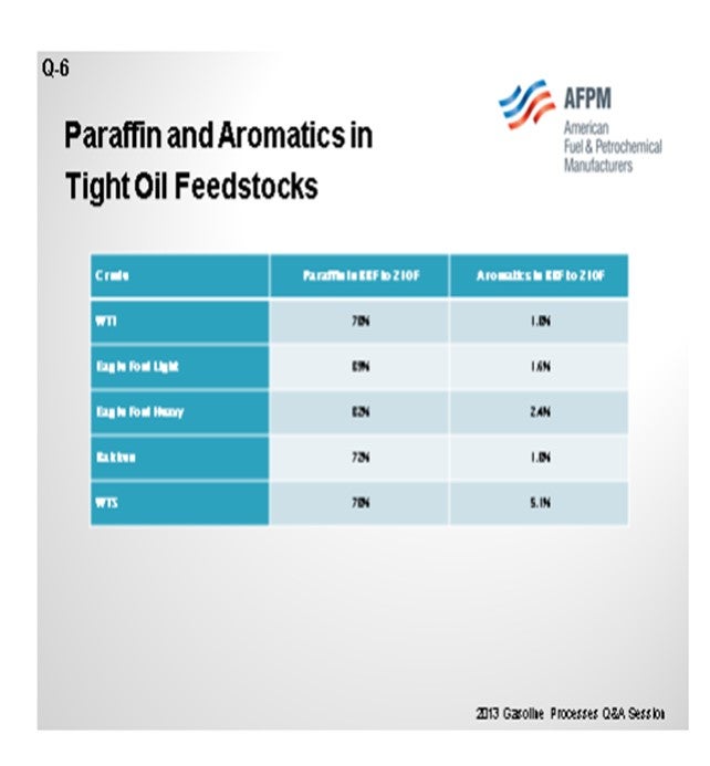
For this question, I looked in our assay database at the light straight-runs since we spoke a little about isomerization then. Really, if you think about benchmark crudes like WTI (West Texas Intermediate) and WTS (West Texas Sour), and if you consider Bakken and some of the Eagle Ford crudes as tight oil crudes, then the only one that really pops out as being meaningfully different is the Eagle Ford Light or the Eagle Ford condensate that some people are running. This generalization is that, at least in light straight-runs, we have a much higher paraffin in that stream. I am not sure I am seeing it. The one caveat I will make is that those WTI and WTS assays are fairly recent. Since they are blended crudes, there might already be a fair amount of that material in those streams.
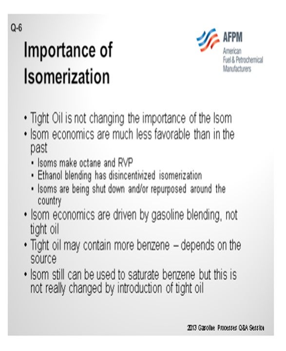
There is really not meaningfully different amount of benzene in the tight oil crudes versus the WTI that we see. As far as the importance of isomerization, if your naphtha does, in fact, have less N+A in it and the reformer performance is dropping off, then you will have to make up that octane somewhere, or make less gasoline, or do something different with crude selection. So the answer for isomerization is sort of yes. Isomerization is nice because it does work on the paraffins. The motor octane is relatively high, and it polishes off benzene. We have isomerization at a number of our plants. We look at it as benzene polisher plus some octane improvement.
STREIT (KBC Advanced Technologies, Inc.)
I think, in general, the economic value of an isomerization unit (Isom) is not really changing that much with the presence of tight oil. The reformers typically have the capability of making up the octane because of what I mentioned before with the ethanol blending. Of course, the problem with isomerization units is that they make octane, but they also make RVP (Reid Vapor Pressure). So as RVP has gotten more restrictive, the value of isomerization units has generally gone down. Many units are being shut down or repurposed around the country. Tight oil may or may not contain more benzene. Isomerization units still have a value for destroying or saturating benzene, but it is not really significantly impacted by the presence of tight oil.
STEVE BAKAS (GE Water & Process Technologies)
Eric, you mentioned that in reforming, there are contaminants that may be of concern regarding tight oils. Do you see the same issue in isomerization?
STREIT (KBC Advanced Technologies, Inc.)
In general, yes. The contaminants are going to be in the naphtha range. How they are distributed between light and heavy I do not know for sure. Many places treat the whole naphtha together, so you do not really worry about that; just split it afterwards. Maybe one of these other guys has a better answer than that. I would tend to say that you still have the same concerns; but personally, I am used to looking at whole naphtha lately as opposed to light versus heavy and where the contaminants lie.
MARK ADAMS (HollyFrontier Corporation)
There does not appear to be a rule for paraffin concentration in light straight-run gasoline from ‘tight oil’ crudes except for the Eagle Ford condensate as shown below. Similarly, there does not appear to be a generalization you can make about benzene in ‘tight oil’ crudes
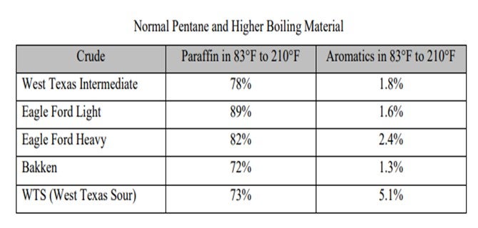
In either case, C5/C6 isomerization is an important process for reducing benzene in gasoline and increasing octane in the gasoline pool. The octane boost comes mostly from converting normal pentane 62 [RON and MON (motor octane number)] 16 RVP to isopentane 92 RON, 90 MON, and 20 RVP. The isomerate product is 83 to 84 RON. In the end, crude quality versus price guidance comes from the economic model as would the incentive to debottleneck the isomerization unit given expected relative values of light crudes.
ERIC STREIT (KBC Advanced Technologies, Inc.)
Isomerization, in itself, has become increasingly less desirable over recent times due to the mandate to increase ethanol in gasoline and the restrictive RVP specifications on finished gasoline. Isomerization units increase octane, which is worth less than it used to be, and increase RVP, which is a major constraint. As a result, isomerization unit economics have suffered greatly. Numerous isomerization units are run at highly reduced rates or shut down completely.
One area in which isomerization units are useful is in saturating benzene. As restrictions on benzene in gasoline have increased, refiners have taken many steps to reduce benzene. One way to reduce benzene is to feed it to an isomerization unit. Not only will the benzene be saturated in the isomerization unit, but many benzene precursors are removed from reformer feed in the process.
The benzene content of tight oil varies with the source. Some tight oils may contain higher levels of benzene, but this depends on the tight oil and the conventional oil to which it is being compared. Isomerization units will continue to have value in reducing the gasoline benzene content, but their value is not significantly affected by the addition of tight oils to the crude mix.
SONI OYEKAN (Prafis Energy Solutions)
The importance of isomerization units for oil refiners, as naphtha feedstock becomes more paraffinic with increased processing of ‘tight oil’ crudes, is highly dependent on refiners’ configuration of naphtha processing units and whether the refiner had elected to use pre-fractionation and/or post-fractionation for meeting low benzene gasoline production across its refineries. Those with multiple refineries and varying configurations of naphtha processing units have broader capabilities and flexibilities for producing a range of gasoline grades and benzene within limits.
The refiners with significant naphtha processing capabilities and who use C5/C6 or mixed C4 through C6 isomerization units have the flexibility to send more of the paraffinic naphtha feed to reformers to produce more reformate octane barrels. The amount of reformate octane barrels produced is dependent on the degree of optimization of the quality of the naphtha feed to the reformer. Isomerization units provide much needed flexibility for upgrading low light naphtha octane fractions and lowering overall refinery reformate and isomerate benzene. The importance of isomerization units is highly dependent on the naphtha processing flexibilities of the refiners. In addition, with potential future regulations for lower total aromatics in gasoline, oxygenate blending, isomerization, and alkylation, units would become increasingly more important for meeting regular and premium gasoline octane blends.
Year
2013
Process
Question 7: Given challenges in gasoline Reid vapor pressure (RVP), benzene, low-carbon fuels, and other requirements, are refiners considering expansion or other changes to make more alkylate? Has increased catalytic polymerization become a consideration?
BULLEN (UOP LLC, A Honeywell Company)
UOP has not observed a big uptake in project activity related to this issue. However, we have observed more interest in revamping existing alkylation units rather than new projects. Compared for the catalytic condensation process, or another process called InAlk™, we observed activity in the area where the refiners are not able to use HF for sulfuric acid. So that is an option. Also, some of the refiners are processing more C5 olefins in their alkylation units to help reduce the RVP in the pool, but this does not always work as well as you think it would on paper. Some of the C5 olefins react via hydrogen transfer and then crack to higher RVP compounds, so they reduce some of that benefit that you get in lower RVP.
ADAMS (HollyFrontier Corporation)
I just think about where we have come with alkylation and polymerization. Historically where octane was the goal in the pool, alkylation won. You could take a certain amount of olefin that you had in your plant and match it up with isobutane, and you could get one and three-quarter times the volume of gasoline component versus how much olefin you started with before it was alkylated. Whereas with the polymerization, you are not really matching up with any other intermediate stream; so, you get the volume shrink and just get about half as much gasoline blending component.
Also, the motor and the research octanes are much closer than the poly gas motor and research octanes. The poly gas is somewhere more in the 90s on the research and then somewhere in the 80s on the motor. If you are motor-limited, then you are looking for alkylation process, which is a better process. If you are limited by gasoline blend olefin content and gasoline, you also want to alkylate. Poly gas does not have any olefins in it, but it is still olefinic.
As far as the environment that we are in today, because all of these light LPGs (liquefied petroleum gases) and condensates, a lot of the ethylene-producing capacity is turning to ethane, propane, and lighter materials. You are not getting the byproducts from the naphtha cracking that you used to get; nor are you getting the benzene, butadiene, butylene, or propylene. So, there are projects that people are building for the Gulf Coast for propane dehydrogenation. If someone is going to make propylene on purpose, you can imagine that it will set a floor for the price of propylene that will either get bid into or out of your alkylation unit. So that is a challenge for expanding alkylation units as well.
As much as I just talked a little about how lousy the poly gas can be in the current circumstances, HollyFrontier bought an old cat poly unit from Western, and we are moving it from a Bloomfield, New Mexico refinery to Woods Cross. This project is a consequence of the capital costs being really low for the relocation compared to the costs associated with the obstacles encountered when expanding an HF alkylation unit. We just looked at that whole map and said that we will just put in the cat poly.
As far as alkylation unit expansions, depending on what you have, which bottlenecks you have to take out (whether is in fractionation or in the reaction section), and if you need a new compressor or not, it is a matter of cost and benefit and those regulatory obstacles. So, we do not have any on the books, but others may.
PATRICK BULLEN (UOP LLC, A Honeywell Company)
Revamp options to increase production in an existing alkylation unit are a major driver for making more alkylate. The handling and safety aspect of using HF and sulfuric acid are already well established, thus making greater use of liquid acid technology more manageable from an environmental and safety perspective.
Some refiners are processing more C5 olefins in their alkylation units to reduce RVP in the pool. However, a fraction of the C5 olefins converts to isopentane via hydrogen transfer and cracking reactions, thus reducing some of the RVP benefit.
For new unit projects, liquid acid alkylation is typically the most cost-effective investment. Alternate technologies, such as UOP Catalytic Condensation Process and UOP Indirect Alkylation (InAlk™) Process, are considered when availability of acid and environment restrictions of using acid are a concern. The UOP InAlk™ process does not use liquid phase acid.
MARK ADAMS (HollyFrontier Corporation)
Alkylate is a high octane (90+), low RVP (5 to 6), low olefin gasoline blendstock that can be a sink for light naphtha blending into the gasoline pool. Expansions of alkylation units would depend on the cost and the economics for additional olefin feed. One of the dynamics of the shale revolution is the abundance of LPGs and the shift in ethylene cracking from naphtha to lighter feeds, such as ethane-propane mix. One of the implications of the shift in ethylene cracker feedstocks is that byproducts of naphtha cracking (such as propylene, butylene, butadiene, and benzene) are not produced and will be shorter in the marketplace. Refiners with access to these markets may find incremental alky feed bid away into a stronger petrochemicals market.
More alkylate is not necessarily the answer to all blending problems. Reformate may be more desirable than alkylate in ethanol blended fuels if distillation is a constraint. Ethanol blended fuels must have a T-50 of 150°F after the addition of ethanol. You might have to start with a T-50 as high as 220°F in the neat gasoline to make the spec after ethanol blending. The T-0 of alkylate and reformate are typically 200°F and 250°F, respectively.
With regard to catalytic polymerization versus alkylation, an advantage of alkylation over polymerization is that you get more barrels of high octane blendstock per barrel of olefin feed because you can match it up with reasonably available isobutane. Additionally, poly gas from catalytic polymerization is less desirable for the gasoline pool than alkylation products from the same feedstocks. The RVP and RON of alkylate and poly gas are comparable, but the MON of the poly gas can be 12 numbers lower than the RON, while the MON-RON difference for alkylate is 2 to 3 numbers. The poly gas product is still an olefin and could be less desirable in certain regions.
HollyFrontier is relocating a catalytic polymerization unit from Bloomfield, New Mexico to Woods Cross, Utah as part of a refinery expansion. The driver for installing the cat poly gas is low capital cost and a lower hurdle for permitting versus an HF alkylation unit expansion.
Year
2013
Process
Question 8: What is the industry experience with de-isobutanizer (DIB) feed pre-heatexchanger or reboiler fouling? What are the typical causes of the fouling? How do you mitigate this problem? Comment on both HF and sulfuric technologies.
BULLEN (UOP LLC, A Honeywell Company)
I am going to talk about HF alkylation units only. The feed pre-heaters for the isostripper or main fractionator have experienced corrosion and fouling. There are several possible causes. One is getting the metallurgy, which is typically carbon steel, too hot. If you go over 160°F in the presence of HF, it gets very corrosive; so, you can lose metal that way. How does that happen? Often it will be caused by the hot side being too hot, which leads to the metal tubes becoming too hot. For instance, if you use the bottoms alkylate for heating up the feed, you can get the skin temperatures on the tubes hot enough to accelerate corrosion. So, we recommend that you actually heat-exchange the isostripper bottoms prior to using it as a pre-heater. If you continue to have issues with corrosion, upgrading to Monel™ or 70/30 copper-nickel (Cu-Ni) is a way to address the issue, though our standards have not changed for this exchanger. It is still carbon steel.
Another possibility for corrosion would be if you are getting excessive carryover from an acid settler and more than just the normal low level. One cannot heat up the feed to dissolve that extra acid into the feed, given the temperatures involved. Again, if the problem cannot be fixed with settler modifications, some refiners have upgraded the tubes again to Monel™ and 70/30 Cu-Ni.
Also, fouling can occur due to scale carryover from the acid settler. When that happens, the particles can settle out and accumulate in the feed pre-heater. We recommend that you actually have the feed go into the exchanger in a downward direction to help flush out the scale particles, so they do not settle out.
Finally, in the isostripper reboiler aspect of corrosion, we typically do not see an issue in HF alkylation units. We are aware of only one unit that had issues. You can read about that in the Answer Book response if you like.
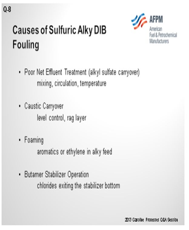
MELDRUM (Phillips 66)
Patrick covered the issues with the HF technology, so I will address my comments to the sulfuric technology. Therein, the primary reasons for DIB fouling from the sulfuric alkylation units are poor net effluent treatment, caustic carryover, foaming, or Butamer stabilizer operations. Poor reactor effluent treatment, either through operations or by design, can allow neutral ester carryover, which would then decompose upon heating in the DIB pre-heat exchanger or in the DIB reboiler. The decomposition of these neutral esters will form SO2 (sulfur dioxide); and when they migrate up the tower, they will create a low pH in the tower overhead leading to corrosion and thus some fouling from the deep products of corrosion. It can occur not only throughout the tower, but also in the pre-heat exchange.
The reboiler can also foul with tar-type deposits as the byproducts of the decomposition of these neutral esters. Good reactor effluent treatment requires effective mixing in both the caustic and alkali wash sections, as well as the waterwash. Also, to have sufficient temperature in the treatment section, at least 120°F is recommended for a butylene feed system. If significant amounts of propylene are being fed, that temperature should also be increased.
Caustic carryover can contribute to salt fouling in the DIB tower. It is generally controlled with good level management in the treatment section and by having a waterwash section after the caustic or alkali wash. High caustic hydrocarbon interface level makes it easier for this carryover to occur, so the management at that level should be given some attention. Foaming carryover from the treater can also occur. It can be caused by aromatics, such as benzene in the alkylate feed, or from ethylene in the feed. It is reported that as little as 50 ppm of benzene in the alkylation feed can cause some net effluent treatment foaming.
Finally, the Butamer stabilizer operations should be operated as such to reject the chlorides overhead from being treated in the off-gas caustic scrubber. If not operated properly, the chlorides can leave the bottom of the stabilizer with the butane that then enters the DIB tower and contributes to corrosion in the DIB system.
ERIC LEETON (UOP LLC, A Honeywell Company)
I want to build on the statement that Craig mentioned about the rag layer. In our settlers and HF alkylation processes, we often look at an acid and hydrocarbon interface. We tend to forget about that emulsion layer. Different feed contaminants change the characteristics of that layer; so, while your apparent acid level may be good, if that emulsion or rag layer expands, you could have unexpected carryover at that perceived acid level. So, watch out for feed contaminants that show up periodically with changes in FCC operations, purchased feedstocks, or the rise of butane in the HF alkylation process.
PUI-NANG LIN (Flint Hills Resources, LP)
I agree with the comment from Eric Leeton on the importance of the emulsion layer in the acid settler. We found out that we have excessive fouling on our DIB pre-heat exchanger on an HF alkylation unit. This fouling occurred at the inlet tube sheet of the exchanger even though our exchanger flow path is a downward flow, as Patrick suggested. We learned that the main criteria is to be sure that the pipe scales I the exchanger inlet piping are cleaned thoroughly during the turnaround. Those loose scales can really cause a lot of problems.
PATRICK BULLEN (UOP LLC, A Honeywell Company)
Corrosion and fouling of isostripper or main fractionator feed pre-heaters has been experienced in some HF alkylation units. The tubes in these pre-heaters are typically carbon steel, and there are often two exchangers in series that use different sources of heat.
One possible cause for corrosion of the tubes is high tube skin temperature. The corrosion rate increases sharply when the carbon steel temperature exceeds about 160°F in the presence of HF. If the hot-side fluid temperature is too high, the skin temperature can be high enough to cause high corrosion rates. Low pressure steam is generally a good choice for the hot-side fluid. Alkylate directly from the bottom of the isostripper column is typically not a good choice. If alkylate is used to heat the isostripper feed, it is best to reduce the alkylate temperature below about 300°F by routing it through another exchanger first (such as an auxiliary reboiler in the depropanizer or upper part of the isostripper). In cases where high tube skin temperature cannot be avoided, the tube metallurgy can be upgraded to 70/30 Cu-Ni Monel™.
Another possible cause of corrosion is excessive acid carryover from the acid settler upstream of the pre-heater. There is always a small amount of free acid carryover from the settler in the form of tiny droplets that are simply too small to settle out inside the settler. This small amount of acid will readily dissolve into the hydrocarbon phase as soon as the temperature increases just a few degrees. If the acid carryover is excessive, the hydrocarbon temperature may have to increase by 20°F or 30°F to fully dissolve the acid. The corrosion rate of carbon steel is much higher when it is in contact with a separate liquid phase of acid (commonly called “free” acid) than when the acid is fully dissolved in the hydrocarbon at the same temperature. The extra time and higher temperature required for free acid to dissolve can result in significant corrosion of carbon steel. This problem can be avoided by proper design of the settler and operation of the unit so that the hydrocarbon flow rate through the settler is not excessive. In cases where acid carryover has been an ongoing problem, some refiners have upgraded the tubes to 70/30 Cu-Ni or Monel™.
A possible cause of fouling of the pre-heater is accumulation of scale that settles out of the flowing hydrocarbon. Scale particles can be carried over from the settler into the isostripper feed. These scale particles can settle out and accumulate in the pre-heater exchangers. This accumulation can be minimized by making sure that all acid-containing streams (which generally contain some small amount of scale) flow through the exchanger in a downward direction (even if the stream is being heated). This may reduce the theoretical efficiency of the clean exchanger a bit, but it also reduces the accumulation of scale inside the exchanger during the run that will result in better overall performance of the exchanger.
The isostripper or main fractionator reboiler in an HF alkylation unit is typically a fired heater; and in UOP’s experience, coking in the tubes of this heater is rare. UOP is aware of only one unit that experienced accumulation of coke-like particulates in the column bottoms circuit. This was due to low reboiler pass flows that resulted in well over 80% vaporization in the tubes. Normal design is 50% vaporization.
PAUL FEARNSIDE (Nalco Champion Energy Services)
On sulfuric units, one of the main constituents of reboiler fouling is corrosion byproducts that are formed higher up in the DIB column and migrate downward. Corrosion can be attributed to acid carryover or neutral ester degradation. A corrosion control program including neutralizers and/or filmers has proven effective in reducing reboiler fouling from this mechanism
Year
2013
Process