Question 29: How many refiners are using Layers of Protection Analysis (LOPA) in their Process Hazard Analysis (PHA) studies? How do they quantify the frequency and consequences of initiating events?
PIZZINI (Phillips 66)
Phillips 66 has used LOPA since 2006 when we do our PHA studies. We apply it to the most severe events and use a scale of 1 to 5 for severity. So, if there is a Consequence 4 or 5, then we will apply LOPA to that event. Generally, those are the scenarios with a loss of containment component. We use the Initiating Cause Likelihoods (ICLs) from Table 5.1 from the Center for Chemical and Process Safety with some slight modifications, but that is our starting point. An example of an Initiating Cause Likelihood is basic control instrument loop failure, which is considered to happen once every 10 years or 10-1. The likelihood of human error on a routine task performed daily is also 10-1. Then you have a human error on a non-routine task performed under high stress, for which we assign a frequency of once a year.
When looking at consequences, it is key to remember to assign the consequence before taking any credit for the safeguards. An example would be an overpressure of a vessel. You must consider the failure of that vessel. We would not take credit for the PRV (pressure relief valve) when assigning the consequence. That would show up as one of the safeguards or layers of protection. When you assign an IPL (independent protection layer), every IPL, in and of itself, will have to be able to stop the event from progressing. So that is our methodology.
PIZZINI (Phillips 66)
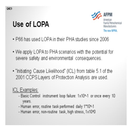
Phillips 66 has used Layers of Protection Analysis since 2006 as the preferred procedure in association with a PHA to comply with ISA- S84. We apply LOPA to PHA scenarios with the potential for severe safety and environmental consequences. The “Initiating Cause Likelihood” (ICL) values from Table 5.1 of the 2001 CCPS Layers of Protection Analysis book are used with some company-specific clarifications and additions. For example, the ICL for a basic instrument
loop failure is 1x10^-1, or once every 10 years. Likelihood for human error, on a routine task performed daily is also given a likelihood of 1x10^-1, but it has an increased likelihood of 1x10^0 for a non-routine task, in a high stress situation.
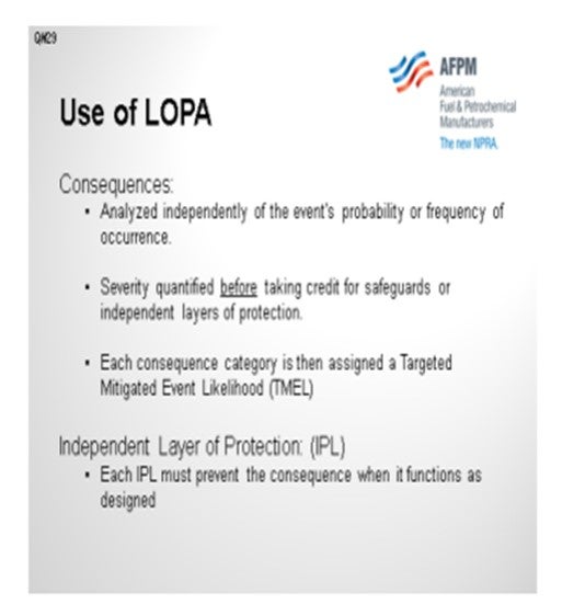
Consequences are analyzed independently of the event's probability or frequency of occurrence. That is, the severity of the consequence is quantified on a scale from 1 to 5 before taking credit for safeguards or independent layers of protection. Each consequence category is then assigned a Targeted Mitigated Event Likelihood (TMEL), or frequency at which the incidents of a particular severity will not be tolerated.
Each independent layer of protection (IPL) must prevent the consequence when it functions as designed.
Year
2012
Process
Question 30: How are water drains routed in alkylation units; for instance, in waterwash or propane drying services? What options exist for separation of the water and entrained light hydrocarbons? How can enclosed systems be monitored?
STEVES (Norton Engineering Consultants, Inc.)
In many units, including both HF (hydrogen fluoride) and sulfuric acid alkylation units, there may be opportunity to drain water from vessels that contain hydrocarbon. Obviously, this can create quite a bit of risk associated with draining hydrocarbons into a sewer system. It is important to control and manage this draining process to avoid getting those hydrocarbons there, especially the lighter hydrocarbons which can travel extensively through sewer systems and
result in fires in remote locations.
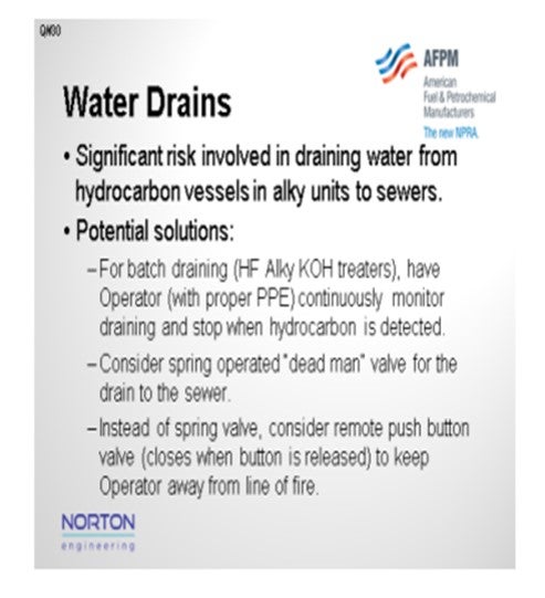
In some refineries for batch removal of water from hydrocarbons, such as what is done on an HF unit from a KOH (potassium hydroxide) treater, the draining is managed by having an operator directly perform the task and stop as soon as he detects hydrocarbon. Sometimes the use of a spring-operated dead-man valve can help ensure that the valve cannot be left open and unattended during the draining process. This activity process can also be done in a remote
location by using a pneumatically operated push-button valve. The valve will only open as long as the operator has his finger on the push button and will close once he let go. However, even with the remote draining, I have seen sewers erupt with a stream of caustic brine as a small number of light hydrocarbons entered the sewer hub.
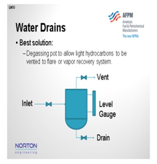
The best solution I have seen is to use a degassing pot for draining the hydrocarbons and caustic mixture from the KOH pot. In this type of operation, you can degas the water stream to either a vent gas recovery system or a flare such that the hydrocarbons have been vented off to allow for the material to then be drained safely to a sewer. Sulfuric unit acids are designed with a degassing pot on the water, leaving the waterwash column to prevent light hydrocarbon from entering the sewer. On HF alkylation units, I have seen the water drains from KOH treaters, in both propane and butane service, routed to a degassing pot like this one shown. The pot is then manually depressured to the flare before the water is discharged to the sewer. The use of this pot reduces the risk associated with light hydrocarbons in the sewer.
PIZZINI (Phillips 66)
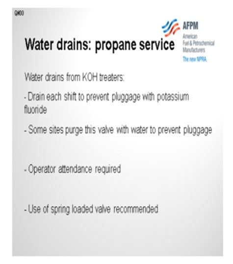
First of all, I would like to second what Chris said about having a disengaging pot. The best option is for that pot to ride on the flare to give the propane or light hydrocarbons a chance to weather while leaving the water that remains at low pressure to go safely to the sewer. One example is that it is a good idea to drain the KOH treater every shift to avoid getting pluggage with salt. We even have some sites which purge that valve with water to prevent the pluggage.
And again, similar to what Chris said, operator attendance is required. In some cases, we do recommend having that dead-man or spring-loaded valve, so there is no chance of the valve being left open and the hydrocarbons escaping.
PIZZINI (Phillips 66)
KOH treaters are recommended to be “blown down” to a disengaging KO pot with the vapor vented off to the flare. The depressured liquid is gravity drained to the sewer with a frequency determined by operator experience. Drain once/shift, or at least once/day to prevent potassium fluoride from setting up. One site injects some water at this valve to keep it from plugging. The operator is required to stay in attendance while draining. Risk can also be reduced by using spring-loaded valve (dead-man valve) designed to close when not held open.
Year
2012
Process
Question 31: What is the panel’s experience with temperature excursions (regeneration and otherwise) leading to the catalyst or equipment damage in reforming and isomerization units?
STEVES (Norton Engineering Consultants, Inc.)
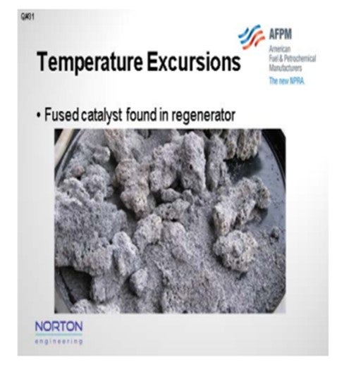
In a refinery where I used to work, our moving-bed reformer experienced a severe temperature excursion in the chlorination zone of the regenerator. After a prolonged outage on the regenerator, the unit was put back into white burns sooner than would have been recommended. On introduction of air/oxygen into the chlorination zone, temperature indicators in the drying zone spiked over 2,000°F, and one of the temperature indicators burned out. Although operation was attempted for a few days beyond the temperature excursion, the unit eventually had to be shut down and the regenerator inspected.
Upon inspection, it was found that the center screen had failed, as shown on the slide.
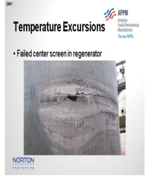
Also, fused catalyst was discovered in the unit. It is believed that temperatures exceeded 3,600°F during the excursion.
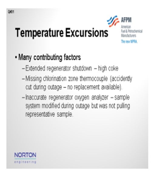
During the subsequent incident investigation, a number of issues were discovered that all seemed to come together in a perfect storm that led to the temperature excursion. Issues included:
• The regeneration section, as I mentioned, had been taken out of service for screen cleaning, and weather delays had prolonged the outage from a targeted three days to six. As a result, the coke level was extremely high.
• Key instrumentation had been modified during the regeneration section outage, which had been planned, including the regeneration thermocouples and the regeneration O2analyzer. However, during the modification of this instrumentation, human error led to a chlorination zone thermocouple being cut, and there were no replacement parts available to try and make the repair before the regenerator needed to be placed back in service.
• The oxygen analyzer sample system was modified during the outage and, upon restart, was not pulling a representative sample of the system.
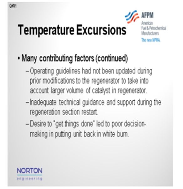
• Operating guidelines had not been modified during a prior outage to take into account a larger catalyst volume within the regeneration system that needed to be circulated before attempting a white burn.
• The unit was demonstrating severe deterioration of performance with the extended regeneration system outage; however, there was no technical guidance that was provided to the operators upon the restart of this regenerator.
• Finally, due to the extended outage and the deteriorating unit performance, there was a desire to get back to “normal” as quickly as possible, which led to poor decision-making when evaluating at what time to put the unit back into white burn.
PIZZINI (Phillips 66)
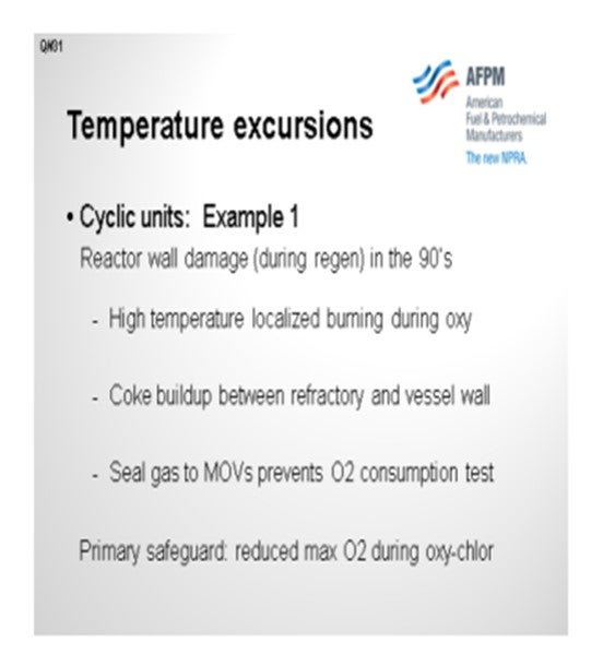
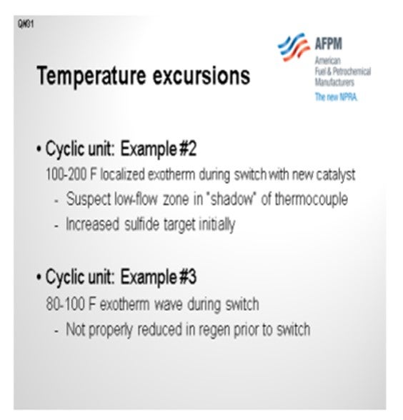
I have three examples of temperature excursions on cyclic reformers. Only the first led to damage, so I will open with that one. This temperature excursion occurred on a spherical cyclic reformer which was going into regeneration about every 10 days. The catalyst section on this reactor has a two-inch layer of refractory. Once we understood the cause of this incident, we realized that coke, over time, had formed between the refractory and the vessel wall. This refractory has a certain number of cracks: not large cracks, but large enough that the hydrocarbon could get behind it and form coke. Also at that time, we were very aggressive with the oxygen target during oxychlorination. That was an actual reactor damage event. Thankfully, it occurred during the regen, so the reactor could be depressured and repaired without any significant safety issue. The follow-up to that, at least in this case, was to limit the O2. Even though we could get better catalyst rejuvenation with high oxygen, we limited it to 2.5%. Our rule of thumb for high temperature burning is that for every one-tenth of a percent of oxygen, we can get another 25°Fof burn temperature. So, imagine that if you are up to 8% or 10% oxygen and there is still coke present, it could get very hot.
This next example was also on a cyclic spherical reactor. It only happened with new catalyst for the first five or six switches. Just picture a six-foot bed of catalyst with a vertical thermocouple. About five feet down (about 80%) in the bed, for the first 15 minutes after the reactor came out of regen and back into the process loop, we saw some exotherms from 100ºF to 200ºF. When we switched on a cyclic reactor, it was already at 900ºF; so we could really afford
to go much hotter. The strategy there was to increase the sulfide in target; but I can tell you that after about 10 regens, the problem went away. My third example is when a reactor got switched before it was reduced. That error created about an 80°F to 100°F exotherm that lasted 30 to 45 minutes. This was a procedural issue. We did not have the hydrogen lined up properly.
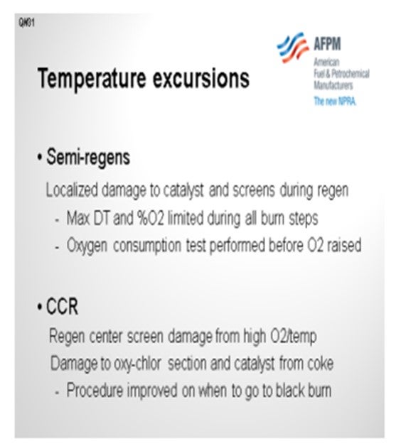
We have seen localized damage on catalyst screens on our semi-regen radial flow reactors. To prevent that problem, we limit the maximum ∆T (delta T; temperature differential) and maximum oxygen during the burn. I am sure everyone else does that as well. Another step to give us that confidence of being able can raise temperatures and O2 levels is what we call the Oxygen Consumption Test. We completely block in the air and nitrogen, and then watch the oxygen analyzer. The criteria are less than one-tenth of a percent of O2 drop over 20 or 30 minutes, and then you know you have burned out everything before you start raising temps.
We also have a couple of CCRs in our system in which we have seen some center screen damage in the regeneration section due to high oxygen and high temperature, as well as some damage to the oxychlorination section when coke was still present on the catalyst. So, we have made it clear, procedurally, when we need to switch from the white burn to the black burn.
PATRICK BULLEN (UOP, A Honeywell Company)
In the isomerization area with an optimized UOP Penex unit, the lead reactor bottom is typically the hottest point in the system and the place where most temperature excursions occur. Most of the time, the excursions are localized and only the catalyst gets damaged, usually due to coking.
PIZZINI (Phillips 66)
I have a follow-up about our isomerization units. We have experience with temperature excursions on several units. All of those are protected with high temperature shutdowns. I do not know if that has always been the case, but it is the case now. Each of the protective shutdown systems is reviewed in terms of its effectiveness. We put each of those shutdowns through a LOPA because the risk is higher on an isomerization unit.
PIZZINI (Phillips 66)
In semi-regeneration units, we maintain maximum ∆T and O2 concentrations to ensure we do not damage catalyst or equipment during regeneration. We do an O2 consumption test before moving into oxychlorination to help ensure no coke balls are burning. We have not experienced semi-regeneration temperature excursions during operation but have experienced localized damage to catalyst and equipment from regeneration.
One of the Phillips 66’s cyclic reformers experienced a temperature excursion and reactor damage in the 1990s due to overheating on a spherical reactor. This hot-wall reactor has2" of refractory in the catalyst zone. Review of the failure indicated that coke had built up over time between cracks in the refractory and the vessel wall, and that this localized coke reached high temperatures during the oxy-chlorination step. Since an oxygen consumption test is impractical given the nitrogen purged isolation valves on this unit, a lower maximum % oxygen was established for all future regenerations.
In CCRs, we have had regenerator center screen damage if the O2/temperatures get too high at the top of the regeneration section. We have also damaged equipment in the oxychlorination section, along with catalyst when coke has entered the oxychlorination zone. We have improved our operating procedures for white burn and black burn to insure this does not occur.
For isomerization units, we have experienced several temperature excursions. In all cases, the high temperature shutdown systems have worked to prevent damage. In each case, an RCFA was completed to determine the cause and resolve the design or operating issue that allowed the excursion to occur in the first place. Consequently, we have instituted a recommended practice for evaluation of all Isomerization High Temperature Shutdown Systems, including LOPA to determine if safety systems are adequate. Where deficiencies are found, safety systems have and continue to be improved. Common causes of isomerization excursions have included: maldistribution of flow, high feed benzene, heat integration and control with new benzene saturation reactors and less than adequate attention to catalyst loading.
ILYA ARANOVICH (GTC Technology)
Typically, in the isomerization process, the hottest reactor is the one in the lag position as it receives the feed that has gone through the first reactor where exothermic reactions of benzene saturation and naphthene ring opening occur. The isomerization reaction itself is exothermic and leads to a positive delta T in the second reactor. With feed excursion containing high X factor having large amounts of benzene and naphthenes and other operational flaws; for example, for the SI-2TM which is the core of the Isomalk-2TM process you can have big temperature excursions and even emergency situations in case the temperature goes over 200oC in the second reactor. The problem with this is at the latter temperature auto hydrocracking reactions begin to occur which lead to a very rapid increase in the reactor temperature. If not noticed and handled properly, the temperature can reach over 400°C and ruin the catalyst. Proper operation and feed control according to the operating guidelines and good practices in analyzing the feed will prevent these temperature excursions from happening and allow operators to reach a minimum10 years of SI-2 service lifetime.
SUBHASH SINGHAL (Kuwait National Petroleum Company)
In semi-regenerative fixed-bed reactors, if the catalyst was sulfur poisoned, temperature excursion is likely during regeneration if O2 is not controlled in the regeneration gas.
Year
2012
Process
Question 32: What are the impacts of the presence of acetone in the alkylation unit feed? How is this formed in the FCC? Comment on both HF and sulfuric units.
STEVES (Norton Engineering Consultants, Inc.)
In both HF and sulfuric acid units, acetone will consume acid, resulting in a reduced acid strength. Regarding sulfuric acid units, some documentation that I got from DuPont STRATCO indicated that one pound of acetone will consume about 10.5 pounds of acid. When talking with some HF alkylation experts, I was told that one pound of acetone in an HF unit will consume about half a pound of acid.
Acetone formation in FCC is suspected to be caused by oxygen carry under from the regenerator into the reactor section. I do not have a lot more detail on that. I would suggest that maybe you ask the FCC panel and see if you can stump them.
Typical acetone concentrations in the alkylation unit feed are about 100 ppm (parts per million) to 200 ppm. In HF alkylation units, levels above 250 ppm can lead to significant production of light ASO (acid-soluble oils), and the acid can become deep red as the acid strength falls.
MUEHLBAUER (Valero Energy Corporation – Benicia Refinery)
Similar to Chris, my experience is that acetone in the alkylation unit feed makes water; so, it requires more acid regeneration for the HF units and higher acid makeup rates for sulfuric units. Within Valero, we do not see acetone as a primary contaminant for our alkylation units. There is only one of our refineries that we actually test for acetone. Most of the oxygenates we found from the FCC were actually phenolic, so they would boil more in the gasoline range rather than end up in the alkylation unit feed.
I want to make one comment. In refineries that have configuration with an upstream oxygenate unit like MTBE/TAME (methyl tertiary butyl ether)/ (tertiary amyl methyl ether) or an isooctene unit, if there is poor fractionation in those units, you could get carryover of alcohol derivatives, such as acetone and dimethyl ether, which would impact alkylation feed. It is obviously becoming much less common in the U.S.; but for international facilities, it may still apply.
DAVID SMITH (UOP, A Honeywell Company)
A potential solution for removing the acetone from the alkylation unit feed is to use the hybrid adsorbent AZ-300. This adsorbent removes a wide variety of oxygenates, including acetone, as well as the water from the alkylation feed.
KURT DETRICK (UOP, A Honeywell Company)
Actually, the acetone can make water in an HF alkylation unit, but not all of it does. In fact, 100 ppm to 200 ppm acetone in the feed to an alkylation unit is not unusual, although it is usually a little less. If that much water actually came into the alkylation unit, you would know it. It would be pretty bad. So, we believe that some of the acetone probably makes water, but not nearly all of it. The majority of it probably works its way out the bottom of the regenerator in most units. At the typical levels that were listed, I think that most units are able to push it out the bottom of the regenerator over time. It does build up in the acid a bit. We have actually done sampling and found acetone in the circulating acid, so it is somewhat stable. One possible cause of high levels of acetone in the FCC unit LPG (liquefied petroleum gas) is insufficient deaeration of the steam used in the FCC stripping section. This allows oxygen to get into the reactor and provides the possibility of making acetone.
RANDY PETERSON (STRATCO® - DuPont)
We have analyzed olefin feed samples from a refiner that complained of higher-than-expected acid consumption in a sulfuric acid alkylation unit. During this analysis, we were surprised to find high levels of acetone ranging between 700 wppm (weight parts per million) and 1200 wppm in the butylene feed from an FCC.
Acetone consumes acid at a rate of 10.6 pounds of acid per pound of acetone [99.2 wt% (weight percent) to 90.0 wt% acid spending range]. Besides consuming significant acid, this contaminant increases the water content (relative to red oils) in the acid, which causes higher corrosion rates within the alkylation unit.
We are not experts on FCC operation, but we have been told that excess instrument air to the FCC reactor may contribute to high acetone levels in the alkylation unit feed.
Year
2012
Process
Question 33: Increased feed sulfur increases acid consumption. How does it affect alkylate yield and/or alkylate properties?
MUEHLBAUER (Valero Energy Corporation – Benicia Refinery)
In HF units, when sulfur is in the feed, it produces acid-soluble oil (ASO), organic fluorides, and polymers, which then have to be removed through the regeneration process. The light ends that are contained in this ASO can put more pressure on the regeneration system and lead to the higher acid losses. So that is the mechanism there. But within Valero, we found that higher ASO really has a minimal impact on alkylate yields. We do see that it can impact the
product sulfur concentration. In one of our facilities, we run as high as 20 ppm sulfur in the alkylate. The main reason for this is ASO entrainment.
We have seen that units which practice internal regeneration are more susceptible to this entrainment, and that is the main area it would come out. We have also found that in units designed with vertical settlers, it is really important to monitor the superficial velocity and acid quality in those separators to make sure you are getting adequate separation.
One other point, which is not on the slide, is that we do have one facility with a sulfuric acid alkylation unit that runs as high as 500 ppm to 1,000 ppm sulfur in the feed. At those levels, we have seen high acid consumption but have not really seen the impact on the distillation properties of the alkylate. In fact, the product sulfur in that alkylate is really low: less than 3ppm. We believe part of that is because of the neutralization section and acid wash that is performed in that unit.
STEVES (Norton Engineering Consultants, Inc.)
I will just echo what Joe said. With normal feed sulfur levels of 10 ppm to 20 ppm maximum, the impact on alkylate yields and properties is minimal. With higher feed sulfur, the acid consumption will become more pronounced and can eventually result in a loss of alkylate yield as you make undesirable acid species.
In HF units, severe sulfur contamination and feed can result in a lot of light ASO production and eventually a yellow discoloration of the alkylate, especially, as Joe said, with internal regeneration. Alkylate endpoint could also increase an octane drop. In sulfuric acid units, severe and prolonged sulfur contamination can lead to an acid runaway, in which case the alkylate yield would drop in an acid runaway situation. Octane would decrease, and the alkylate can turn purple.
KURT DETRICK (UOP, A Honeywell Company)
Just one more comment on the alkylate properties. I think that the sulfur itself is not directly affecting the alkylate properties, such as the endpoint or the color. Rather, it is the drop in acid purity, which occurs as a result of a sulfur upset, that tends to cause these high endpoints and the color in the alkylate. The reason that happens is because the ASO that comes from the sulfur tends to be a fairly light boiling ASO. So, if you try to run the regenerator or rerun column
at about the same temperatures as normal, then you might boil it overhead. It stays in the system that way instead of getting rejected in the bottom of the rerun column or regenerator. If you know you had the sulfur upset and can drop the rerun or regenerator temperatures a little ahead of time to get that ASO out the bottom of the regenerator, then the effect on the alkylate endpoint will be minimized.
RANDY PETERSON (STRATCO® - DuPont)
We were contacted by a refiner that has very high levels of sulfur compounds in the olefin fed to their sulfuric acid alkylation unit. Most butylene feeds are treated with caustic washes or mercaptan extraction units prior to alkylation and usually contains less than 20 ppm total sulfur. However, this particular refiner’s feed typically contains approximately 500 ppm and sometimes well over 1,000 ppm of sulfur compounds. They see a strong correlation between the feed sulfur content and acid consumption which we would expect. However, they see much higher acid consumption than what we predicted.
We performed a series of pilot plant runs where we spiked the feed with various quantities of typical sulfur contaminants, such as ethyl mercaptan. In summary, we found that the sulfur components have about double the acid consumption than what we have previously published. For example, ethyl mercaptan consumes about 31 pounds of acid per pound of contaminant (99.2 wt.% to 90.0 wt.% acid spending range) versus the 15.7 pounds of acid per
pound of contaminant that STRATCO® DuPont has published in the past.
As far as alkylate product specifications, we saw no change in D-86 T90 or endpoint with changes in feed sulfur in our pilot plant. The refiner also reported that the alkylate product typically contains less than 10 ppm sulfur no matter the quantity in the feed. They have a modern effluent treating system with an Acid Wash which may help explain the low sulfur levels in their product.
Year
2012
Process
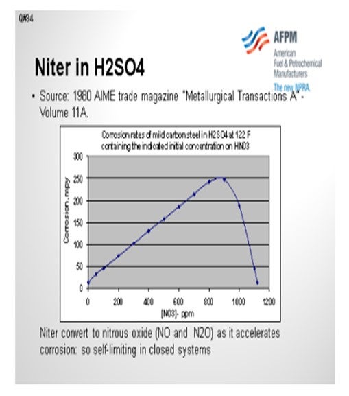
Question 34: Fresh sulfuric acid fed to an alkylation unit can contain niter (nitrosylsulfuric acid) which may lead to excessive corrosion. What is niter; what does it do; can we test for it; and how can we reduce the levels in our fresh acid?
MUEHLBAUER (Valero Energy Corporation – Benicia Refinery)
“Niter” is actually a common term referring to the amount of NOx (nitrogen oxide) or nitrates in the sulfuric acid. It is actually generated in the sulfuric acid regeneration process. One of the first steps you go through in acid regeneration is a combustion furnace. In that combustion furnace, you can generate NOx, which is really a function of your peak flame temperature and excess oxygen: the normal NOx contributors. But then, what the regeneration facility does with
that NOx is what can cause a variation in the niter concentrations. Some units are designed with a mist break eliminator that essentially can entrain this niter in the product fresh sulfuric acid, in which case the concentration in that stream would be much higher.
Other facilities either employ different technology for NOx control, or they are able to segregate the niter and reroute it to the spent acid. The niter stream becomes a feed to the regeneration unit, which would then get reprocessed and not end up in the product fresh acid. Within Valero, we actually have not had much experience with niter-related corrosion, nor have we had any of our corrosion caused by niter. Our acid supplier told me that our niter concentration typically ranges from 25 ppm to 50 ppm levels.
PIZZINI (Phillips 66)
I want to give a nod to Randy Peterson who provided a lot of the information for this response. As Joe said, niter is the NOx compound that can exist in the finished sulfuric acid. There are wet chemistry methods that can quantitatively measure how much niter is present. One method is a color change test with iron sulfate. I know that DuPont and Rhodia both have methods. You need to get in touch with either of those companies to get the method. The amount of NOx is influenced by how hot the acid regen furnace is operating. So, if you are burning just all-natural gas for heat, this high temperature flame will increase the NOx versus, say, a spent acid furnace that is burning acid gas. We have input indicating that the typical niter levels from a two-stage spent acid furnace are 25 ppm to 40 ppm.
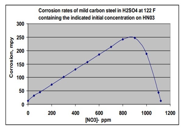
The chart on this slide was created based on an equation included in an article in a 1980 metallurgical trade journal. I plotted out the information to show the corrosion rate of carbon steel in mils per year, based on a scale of 0 to 300, relative to how much nitrate is present in strong sulfuric acid at 122ºF. So, if you get upwards of 800 ppm of nitrates, corrosion could be very aggressive. The good news is that the NOx is consumed in that reaction, so it is not self0-sustaining and does eventually disappear in a closed system. If you get above 1,000 ppm of niter in acid, then the corrosion rate will actually drop as a result of having a passivation effect.
PIZZINI (Phillips 66)
“Niter” is a term that describes the amount of dissolved nitrogen oxides in sulfuric acid. The term is applied to the amount of either NO3 (nitrate) or NO2- (nitrite) present. This is a relevant question, because increased levels of niter will affect the corrosion rate of the acid on carbon steel since these compounds attack the protective ferrous sulfate coating on the metal surface. There are “wet-chemistry” methods to determine the amount of niter in sulfuric acid, available from DuPont and Rhodia. This test uses ferrous sulfate which reacts with nitrates and nitrites to produce a red color. The amount of niter in sulfuric acid is related to the conditions in the spent acid regeneration furnace, where hotter flames (e.g., burning only natural gas) or the presence of ammonia in the fuel gas will lead to higher NOx levels in the resulting fresh acid. For example, a two-stage spent acid furnace would be expected to have niter levels in the 25 ppm to 40 ppm range in the fresh acid.
Corrosion rate effects on mild carbon steel in concentrated sulfuric acid were documented in a 1980 AIME (American Institute of Mechanical Engineers) trade magazine, Metallurgical Transactions A, Volume 11A. The chart below was creating using information from that article. Note that the corrosion rate increases with nitrate concentrations up to approximately 1,000 ppm, and then decreased markedly at higher nitrate concentrations, where the steel passivity is re-established. Also note that the nitrates and nitrites are reduced (converts to NO and N2O gasses) as they accelerate corrosion and are therefore self-limiting in closed systems.
RANDY PETERSON (STRATCO® - DuPont)
We have recently seen excessive corrosion problems in sulfuric acid alkylation units that are being run very close to optimum design conditions. After significant trouble shooting and testing for many contaminants, we believe that unit corrosion is significantly accelerated by a contaminant found in all fresh sulfuric acid. This contaminant is nicknamed “niter” and is mostly composed of nitrosylsulfuric acid (NSA). Its chemical formula is NOHSO4 and it acts as an
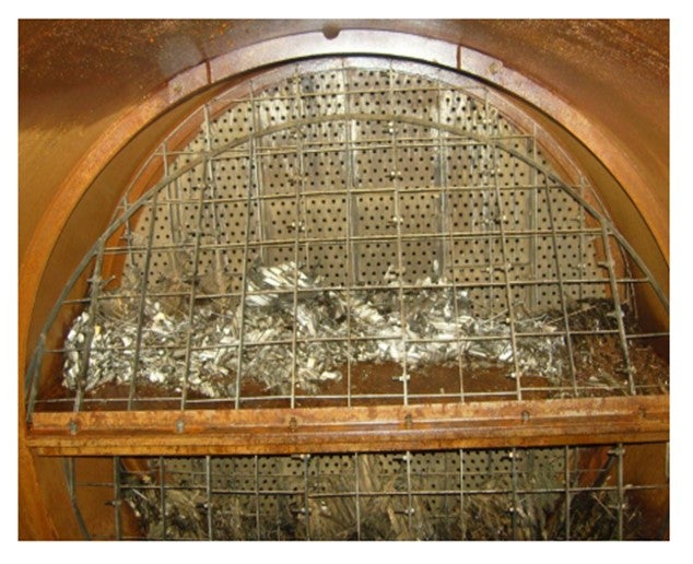
oxidizer that apparently is very corrosive to carbon steel and Alloy 20. Niter is formed in the sulfuric acid regeneration plant (SAR) and is most concentrated in the drains from the mist eliminators within the absorption towers (i.e., final absorption and interpass absorption towers). These drains can either be allowed to drip into the tower bottoms where the niter combines with the product acid or can be collected within the towers and routed to another destination. This destination is typically either the 99 wt.% product acid tanks, the 90 wt% spent acid tank (SAR feed) or directly into the SAR furnace.
We have found that if the niter-rich drains are sent to the product acid, the niter content in the fresh acid sent to the alkylation unit can be as high as 300 ppm. If the drains are sent to the spent acid tank or directly to the furnace, most of the niter is converted to N2 within the SAR and harmlessly exits the stack with the flue gas. The product acid then typically contains less than 30 ppm niter. We suggest that you contact your sulfuric acid supplier and ask them, “Where are you sending the niter-rich drains from the mist eliminators?” Of course, we recommend that they not be added to the fresh acid that you purchase. If you have your own onsite SAR and the drains are not routed to the furnace or spent acid tank, we recommend that you contact your SAR licensor for Best Practice recommendations. If you would like DuPont’s colorimetric test procedure for measuring niter in fresh acid, please email me at: j-randall.peterson@dupont.com.
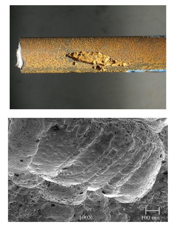
Here are a few pictures of what we believe to be niter-induced corrosion. The first picture is of Alloy 20 Acid Wash coalescing media that had gone “active” and collapsed within two years. This is typically considered a very mild service, liquid-full, with mostly isobutane, some alkylate, and less than 5 LV% of 99 wt.% acid. The temperature is approximately 85°F and the velocity is extremely low (<10 ft/min (feet per minute). The Chevron-type Alloy 20 coalescing
media originally filled the entire area between the wire grids. Notice that the carbon steel vessel and the 316 SS (stainless steel) perforated plate and support grids appear to still be in very good condition. Alloy 20 is a specialty metal that is specifically formulated for harsh sulfuric acid services. The failed Alloy 20 was analyzed by DuPont metallurgists and found to have the proper composition.
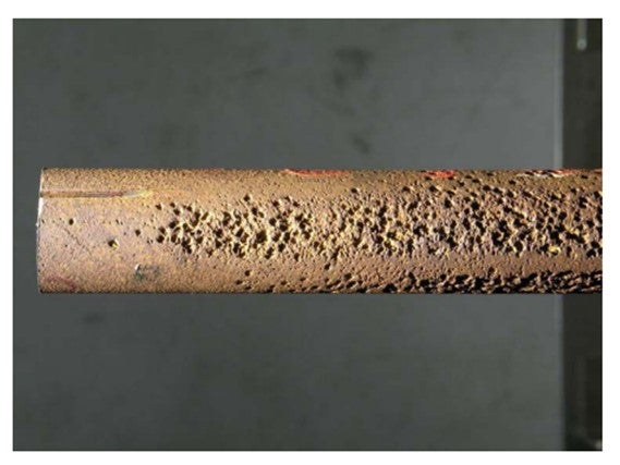
The following pictures are samples cut from a prematurely failed carbon steel Contactor™ reactor tube bundle. These tubes failed in less than two years under what is typically considered mild conditions (<50°F and 92 wt% acid). Pitting is not a typical failure mechanism of carbon steel in sulfuric acid service. This is the primary clue that led us to look for the presence of oxidizers such as niter.
Year
2012
Process


