
Question 17: What minimum nozzle velocities are required in air and steam distributors to prevent catalyst backflow and subsequent erosion? Please consider both upward and downward pointing nozzles.
HEATER (BASF Catalysts)
The FCC has many distributors: combustion air, stripping steam, feed nozzles, and torch oil. Many routine FCC problems are the result of poor distributor operation; for example, poor yields due to poor catalyst/oil contact, poor stripping due to lack of catalyst/steam contact, and excessive attrition due to distributor damage.
Common points of nozzle design:
- Standard dual diameter nozzles: You have an orifice controlling the pressure drop to ensure even distribution and no catalyst backflow and a nozzle diameter setting an acceptable outlet velocity.
- You need a sufficient distance from the orifice to the nozzle, such as if there is fully developed flow in the nozzle before it exits.
- You need sufficient cover of the process area to ensure good vapor/catalyst contact. This can be done in two different ways. You can have a large number of nozzles; that is, one square foot per process area. Or, you can have nozzles with high outlet velocity to rely on jet penetration.
Typical distributor and nozzle design includes the following:
- Orifices sized to give pressure drop equal to 30% of static height above the distributor,
- Nozzle outlet velocity of 90 fps to 100 fps,
- Minimum nozzle length of 5.2 times the difference between the nozzle diameter and the orifice diameter (engineering firms tend to use 1.5 to 3), and
- Drains to allow wet media to discharge freely.
To prevent catalyst backflow into nozzles, there are two answers. For a single nozzle, industry standard is to maintain 25 fps velocity in the orifice area. That seems like a low velocity, but that should keep the nozzle clear. For a distributor, the parameter is minimum pressure drop. The guideline is 10% to 30% of static bed height. Commonly, this is 10% for downward facing nozzles and 30% for upward facing nozzles.
The most likely mechanism for catalyst backflow is the sudden loss of pressure of the flowing media, resulting in instantaneous backflow. This may require waiting until the next downtown to unplug the distributor. Any distributor can experience backflow and plugging if the flow gets sufficiently low.
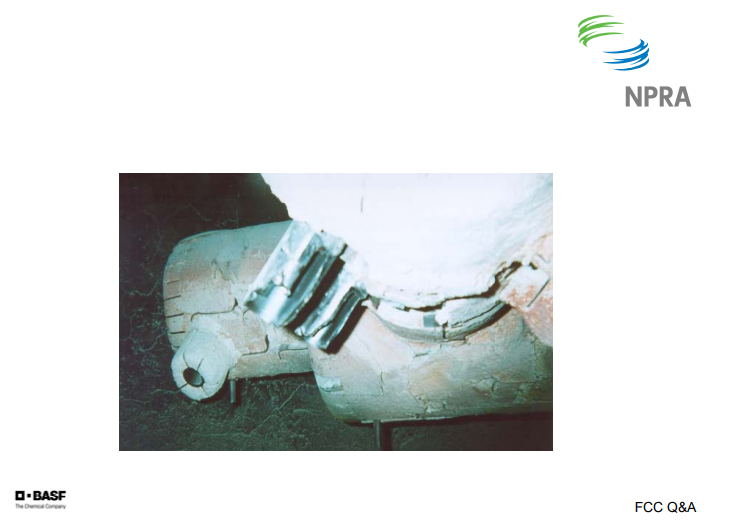
This is a picture of an air grid where there is severe erosion on the nozzles in front due to the addition of the catalyst.
THOMPSON (Chevron)
We generally focus on nozzle pressure drop rather than velocity as a key criteria for the nozzle design. We limit nozzle velocities to maximum 250 fps and prefer velocities below 200 fps. Recently, design distributors have been designed with air velocities of 80 fps to 100 fps. We follow the industry criteria of 30% of the bed pressure drop for upward pointing nozzles and 10% of the bed pressure drop for downward pointing nozzles.
REZA SADEGHBEIGI (RMS Engineering)
Ralph brought up a good point for designing these nozzles: that it has to have a decent pressure drop. However, one thing you need to keep in mind is that sometimes the engineer who designed this put in his calculation, which comes out to be 1/8 of an inch orifice. You have to use common sense because you can design for four pounds or five pounds or 2 pounds psi. If the hole turned out to be too small, which has happened in many cases, you will plug up that nozzle orifice very quickly. So there should be a minimum requirement on the design of the orifice when you design this distributor because otherwise the catalyst can easily block that orifice and plug the nozzle.
The other thing that you have to think about is: Can the distributor absorb shocks? The support of that distributor is very important because you are never going to have dry catalyst every day, day in and day out. You are going to have water. So if you are going to have a wet catalyst, how is the distributor going to be able to handle that? In the last two years, we have designed four steam distributors that have been installed with great success. These are some of the things that you need to keep in mind, rather than all those velocities and ΔPs.
Mechanical designs: You know, they show you through factory lines so that nozzle velocity is low. Therefore, the attrition rate is—The other thing is that I see in our industry is that lack of communication between a designer and a refiner. Usually, the designer goes to the distributor and they think that, “Oh. Two pound per thousand is good or three pound per thousand.” They put it in and they want to raise the stripping stream because they see that when they increase the stripping stream, the bed temperature goes down. But unfortunately, the stripper was not designed for that. So guess what happens? Attrition goes up. A lot of times, I see that these distributors do not have that flexibility in them. If you design for 5000, can you really go to 10,000 if you needed that?
The other thing is that during startup, especially in a steam distributor, I recommend that you have a provision: If you have a wet steam, put some nitrogen in there. Automatically, nitrogen will come on if you lose the pressure. Or better than that, have a minimum flow around your control valve all the time. Put an orifice in there. That way, if you lost a control valve, you always have minimum amount of stream going through that, which would not plug it. A lot of these problem happen during outages. You lost the power. You come back up—or have attrition. You go to a pressure server; it is partially plugged. They follow all that design criteria. So those are some of the things that you really need to talk to your designer, or whoever it is, to make sure that you have a nice package.
ZIAD JAWAD (Shaw Stone & Webster)
I would agree that different distributor designs may have different criteria. One thing to keep in mind is designs where there is a dampening effect in the bed; for example, in a Model 2 where there is an overflow well and the bottom of the bed does not have fluidized catalyst. You would experience a dampening effect and there may be a difference in the design criteria between different technologies. But in other designs, for example in a reactor where spent catalyst is exiting through the bottom of the bed and the catalyst is fully fluidized above and below the ring, there is less of a difference in the criteria.
Submitter
Question 18: Some refiners have installed gas injection in FCC secondary cyclone diplegs to increase capacity and avoid defluidization problems. Please describe your experience operating with gas addition in the diplegs and any maintenance issues. What advice would you give to others considering this installation?
THOMPSON (Chevron)
Cyclone dipleg aeration is a technique used to improve cyclone dipleg fluidization. It involves adding steam, a stream of purge gas—usually air or steam—to the dipleg just ahead of the trickle valve. It ensures that the cyclone dipleg does not defluidize and plug. This can be a problem for lightly-loaded secondary cyclone diplegs.
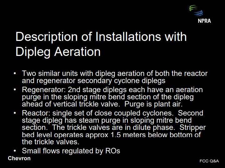
We have two similar units with dipleg aeration, both are reactor and generator secondary cyclone diplegs. One regenerator has three sets of two-stage cyclones; the other has two sets of two-stage cyclones. Both have air purges just upstream of the trickle valve. Air purge on these purges is controlled by a restriction orifice. These systems have worked pretty well. We have not had any plugging issues with the aeration system or loss of the lines. We also have the system that was installed on the reactor side on the secondaries and that, too, has worked well. Those were actually installed after we had some problems initially after a revamp. There were a lot of concerns about routing the piping: thermal expansion. But on these units at least, it looks like that system has worked out very well and we have not had piping failures.

HEATER (BASF Catalysts)
Some FCCs use conventional pressure taps to measure the flowing catalyst density in the diplegs. Purge gas, typically nitrogen (N2), provides some aeration. External aeration is not a common practice due to poor mechanical reliability of the piping and connections. It is possible to over-aerate the dipleg. The better option is well designed trickle valves so as to not allow defluidization in the diplegs, especially during startups during which the loading can be so light that the residence time is long and defluidization can occur.
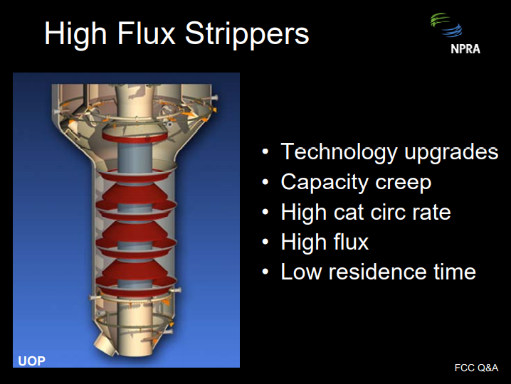
Question 19: FCC revamps commonly include technology upgrades, which increase the catalyst circulation rate, which then increases the stripper flux and reduces the stripper residence time. Please describe your experience with the high flux stripper and its performance. What is the maximum flux you have achieved? What is the minimum residence time you have achieved? Will the use of high efficiency stripper internals reduce the required residence time?
WALKER (UOP)
In addition to technology upgrades, capacity creep is a major factor contributing to ever-higher catalyst circulation rates. Together, these factors are indeed forcing refiners to push the boundary of stripper flux and residence time experience.
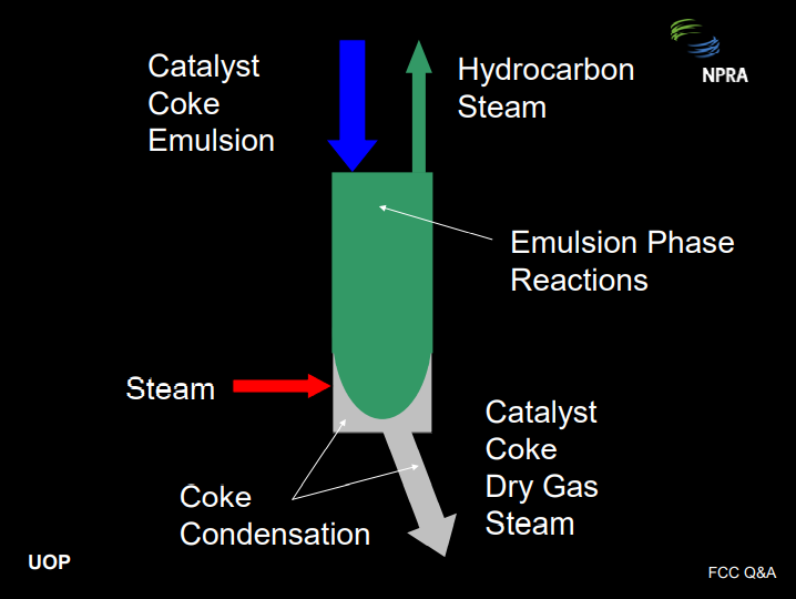
The basic function of the stripper is to recover hydrocarbon product from the emulsion phase, which is entrained with the catalyst after it leaves the riser termination device. This is done using steam that is distributed into the bottom of the stripper. As catalyst leaves the riser termination device, it carries with it hydrocarbon vapors in the emulsion phase. These hydrocarbons should be stripped out as quickly as possible for two reasons. First of all, if the hydrocarbon is not stripped out, it will enter the regenerator and burn there. This will increase the regenerator temperature, reduce the cat-to-oil ratio, drive down conversion, and increase dry gas: all bad things. Secondly, the hydrocarbon vapors in the emulsion phase will continue to react non-selectively in the stripper dense bed, depressing product value.
A catalyst stripper can be readily compared with a reactive distillation column. The emulsion phase and the coke are both reactive. However, the reactions in the stripper are more selective to dry gas and coke compared with the reactions in the riser, so we want to suppress these reactions. The objective is to strip out the emulsion phase as quickly as possible. The coke condensation reactions will continue all the way down the spent standpipe, producing dry gas all along the way, but these are not as harmful as the emulsion phase reactions.
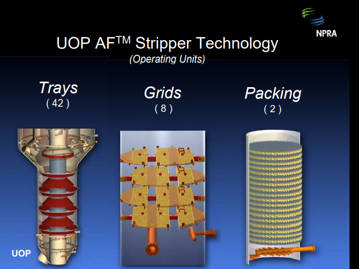
As with ordinary distillation columns, stripping efficiency can be improved by increasing the stripping steam rate, increasing the number of stages, which requires more volume and residence time, or improving the efficiency of each stage. So the answer is yes, use of modern, high efficiency internals will definitely reduce the required residence time.
At UOP, we have several strippers operating at 90 Mlb/hr/ft2 to 120 Mlb/hr/ft2 flux, with corresponding residence times of 35 seconds to 45 seconds. We have two operating right at 120 Mlb/hr/ft2 and one in design for around 130 Mlb/hr/ft2 . Generally, we have observed that strippers with very long residence times do not respond to decreasing stripper level. However, with some stripper internals, we do see a negative response to lower levels for strippers with very short residence times; i.e., under 60 seconds. So this observation does demonstrate that there is a real penalty for ever-shorter residence time strippers and the need for high efficiency internals.
ASDOURIAN (Sunoco Inc.)
I will just speak qualitatively to these questions. High flux stripping has occurred in several of our FCCUs. We found that our annular strippers are most vulnerable. Strippers have been upgraded by adding stages, modifying steam distribution, adding a means for radial catalyst distribution, and/or adding more cross-sectional flow area. Prior to the upgrades, hydrogen and coke ran higher than desired, and obviously these changes improved that situation. Also, regenerator temperature and flue gas percent CO was very sensitive to stripper level and/or stripping steam rates. Upgrades have resulted in the less sensitivity stripper conditions, as well as the lower hydrogen and coke. Also, another side benefit of this is that it results in a reduction in the sour water make if sour water management or conservations are an issue.
SALIP SONI (ABB Lummus)
I think there is some clarification required regarding what the residence time really means because in some strippers—like the conventional design backwards—the residence time is calculated based on the total volume of the stripper, but effective volume is much lower because the stripper area is reduced to the cross-sectional area of the stripper. The catalyst is moving faster than if the whole cross-section area was available to flow. So, I would call that a superficial residence time, but the technical residence time is slower. And if you install the modern devices, they add volume for the catalyst to flow or the cross-section area for the catalyst to flow through, then the catalyst will be flowing slower. Though the residence time appears slower, based on the stripper volume, effective residence time is probably the same. So, Lummus has installed the new advanced modular grade stripper internals in the stripper where residence time is only 30 seconds. It improved the performance of the stripper and reduced the stripping steam rate.
Submitter
Question 20: Several refiners are considering continuous operation of the combustion air heater to maintain a minimum regenerator temperature when processing light, severely hydrotreated feedstocks. What control systems, design features, and other general precautions should be considered?
HOWELL (Holly Refining)
As I previously mentioned, Holly is constructing mild hydrocrackers at both of their refineries. Of obvious concern to Operations and Engineering is where the FCC heat elements will settle out. Since we do not yet have experience operating the FCC on the severely hydrotreated feeds, when we saw this question, our immediate thought was, “My, that is creative and perhaps we ought to consider that.” We do have some experience with our TCC unit at Woods Cross. There are still a number of individuals who remember running that. We did have a combustion air preheater that we continuously ran for that process. However before we would consider this, we would obviously have to address reliability and safety issues of that combustion air preheater to make sure that the safety shutdown systems or safety interlock systems were correctly designed and installed. We also need to have an assurance of reliability for that combustion air preheater and for the controls on that, which were also a little bit of problem on our TCC unit.
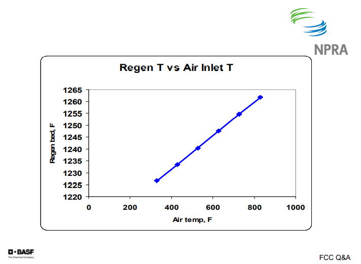
HEATER (BASF Catalysts) Design of the air distributor and nozzles must be checked for continuous operation at higher temperatures. This will result in higher nozzle velocities due to actual acfm of air flow. For this reason, as well as for smoothing out of the heat balance, an automatic temperature control scheme is highly recommended. A better option is to increase the e-cat activity with higher ppb additions and/or higher activity with fresh catalysts.
This chart shows data from our model: air in the temperature versus the regenerator temperature. You can see about a 400°F increase in air temperature gives you about 30°F increase in regenerator temperature.
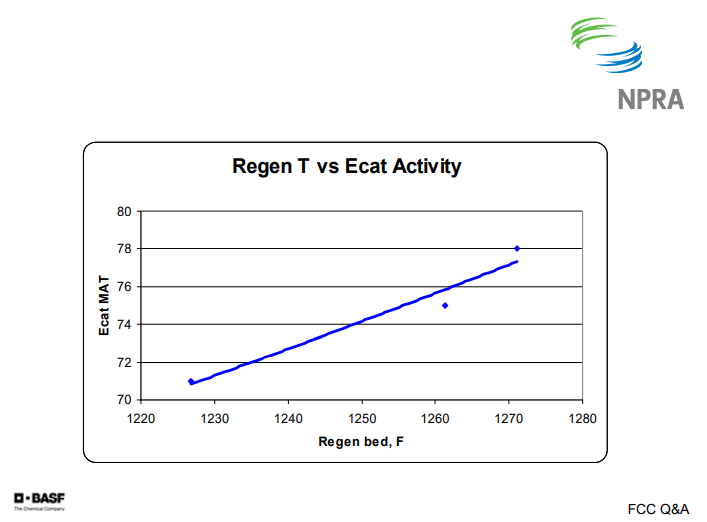
This next chart shows regenerator temperature versus e-cat activity. In this case, about six numbers of activity gives you about 35°F of regenerator temperature. So for our customers with severely hydrotreated feeds, we typically recommend a quite high e-cat activity level.
WARDINSKY (ConocoPhillips)
Two of our FCCs that are processing severely heated feedstocks have operated their preheaters for extended periods. On these units, we implemented calculations in the DCS system to monitor the air distributor nozzle exit velocities. With a 1000°F air temperature, the nozzle exit velocities approached 300 fps, which obviously can lead to catalyst attrition and potential air distributor damage. Igniting air preheaters is always a challenge, as is keeping the burner tips from plugging the scale. Several steps can be taken to ensure that the air preheaters are available during a run, including increasing air preheater inspection and cleaning scope during the turnaround, installing a strainer in the fuel gas line to prevent scale from plugging nozzle tips, and implementing state-of-the-air ignition and flame monitoring systems.
I will say that this was an issue we were looking at for these two units. We have since modified the catalyst. Basically, we took out the matrix component and it is just pretty much all zeolite. Those units are now running with pretty reasonable regen dense bed temperatures. So, we have been able to turn off the air heaters.
PHILLIP NICCUM (KBR)
One of the things to bear in mind with regard to the safety of the air heater is that temperature and flame monitors only go so far. Many of you, I am sure, have seen cases where if you have a fuel that may want to be liquid, such as an LPG or even an LCO. And if your vaporizer is not working properly, these materials can run down the line in a liquid state and burn downstream of your TIs. If some of it burned downstream of your TIs, you could find your air distributor destroyed.
Submitter
Question 21: When operating with one or more catalyst coolers on a regenerator, what control philosophy do you employ (e.g., constant heat duty, constant regenerator temperature, etc.)? What are the advantages and disadvantages for each approach? How does operating in full- or partial-burn impact the control decision?
WALKER (UOP)
First of all, what is a catalyst cooler? A catalyst cooler is basically a vertical shell-and-tube heat exchanger attached to the regenerator. The cooler extracts high quality heat from the catalyst in the regenerator to produce high pressure steam. UOP’s design uses a bayonet-tubed catalyst cooler. Catalyst flows down through the shell. Fluidization air, which comes in, is used to control the duty, as well as the catalyst flow rate, which comes down and exits through a cooled catalyst standpipe. A slide valve (that is not shown) is installed in the cooled catalyst standpipe, which is used to control the flow rate of the catalyst, and the duty-fluidization air is also used to adjust the duty.
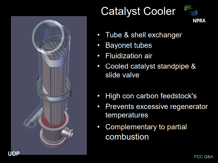
Increasing the coke yield for high concarbon feedstocks is necessary to increase the conversion, but we also need to prevent excessive regenerator temperatures. Installing a catalyst cooler is one way to increase the coke yield from the unit. There are two other primary ways to do this: reduce the feed temperature or reduce the CO2-to-CO ratio for units operating in partial-burn.
The question has two parts. The first part has to do with the control strategy. I have seen a number of strategies used. On two-stage regenerators, we typically control the second-stage temperature by adjusting the cooled catalyst slide valve position. Another common strategy is to manually set the cooled catalyst slide valve position and the fluidization airflow rate. This is similar to a fixed-duty strategy, but not exactly, because the regenerator temperature can also shift for other reasons, such as feed quality changes. This can change the MTD and the heat transfer.
The second part of the question has to do with how you pick the regenerator temperature or how you pick your cat cooler duty. Let’s say it is a constant heat-duty strategy. Like any other process variable, the heat duty of the catalyst cooler should be dictated by the refinery economics—for example, the LP model—and subject to constraints. The benefits of increasing the cat cooler duty are to reduce the regenerator temperature, increase the cat-to-oil ratio, and conversion. The lower regen temperature will reduce the catalyst consumption rate and will reduce the dry gas yield. The downside is that it will increase the coke yield, reducing the liquid product yields, but at increased conversion.
The coke is converted to steam in the catalyst cooler, and so it may impact the refinery steam balance. Also, more air is required when the coke yield increases. If the regen temperature is quite high—for example, 1375°F—your catalyst costs will rise dramatically compared to an operation at 1325°F, especially if you have resid feed causing high metals on the e-cat. Thus, there is a favorable regenerator temperature-operating window that can be achieved by using a cat cooler for control. But as typical with FCC units, there is a balance between the process variables used to optimize the unit.
WARDINSKY (ConocoPhillips)
The most common approach for full-burn cat cooler operations we have experience with is to allow the heat removal duty be an operating variable at a cat circulation limit and/or an air blower limit. Setting the cat cooler duty at some established minimum provides a more consistent steam generation rate to the plant’s steam system. This may be advantageous for units relying on steam to power rotating equipment or for plants that are short on high pressure steam. In our experience, most partial-burn units would operate using the same philosophy. Again, you are going to want to run up against a catalyst circulation limit to increase conversion.
Keep in mind that the use of a cat cooler is going to result in increased coke combustion in order to satisfy the heat balance; and thus, you are going to consume feedstock that could otherwise be converted to product.
THOMPSON (Chevron) We have four units that operate with cat coolers. They are either on the single-stage regenerators or the full-burn stage of a two-stage regenerator. We do not have any experience using a cat cooler on a partial-combustion unit.
Cat coolers are operated to minimize the regenerator bed temperature to a limit, which is usually either air supply or cat circulation. That optimization is an advanced control application that we have implemented on those units. We only use straight-duty control if we reach a cooler or steam system limit. The benefits for minimizing regenerator temperature include maximizing cat circulation, minimizing dry gas production, minimizing swings during feed changes, and, of course, reduction of cat deactivation.
PHILLIP NICCUM (KBR)
For a complete combustion operation, it is usually pretty straight-forward for the operators. For instance, with a KBR Dense-Based Catalyst Cooler, you can control the regenerator bed temperature by adjusting the catalyst circulation rate using the TIC very carefully. But in a partial-burn unit, you have a couple of other options. One option would be to just base-load the cooler steam production and use the air rate to adjust the regenerator temperature, like some people are used to doing in a partial-burn operation. Another way to do it would be to actually control the heat removal to control the temperature and use your CO composition and the flue gas to figure out how much air rate you need to put in the regenerator.
REZA SADEGHBEIGI (RMS Engineering)
I have to share with you this sad story. I was in a unit about a month ago. They run resid and they have a cat cooler, so you would think that they should use the cat cooler to minimize the bed temperature and all the good stuff that we just mentioned. Well, they cannot use it because their minimum bed temperature that they need to hold is 1360°F. Why? Because if they go below 1360°F, then the afterburn takes off and they have to add promoter. And when they add a promoter, NOx takes off. So a lot of times, when we shove more feed through this type of a unit, we like to have a nice low bed temperature. But if your regenerator is not designed properly, you do not have a good air and spent catalyst distribution or enough residence time in the regenerator, so the cat cooler does not do anything for you. It is just sitting there. So when you go through that, you really need to look at the total picture: Where am I on my regenerator in terms of keeping the bed temperature down and at a reasonable number?
WALKER (UOP)
The air distribution and coke distribution are key. You have to have those in place in order to drive the temperature down.
WARDINSKY (ConocoPhillips)
You want to consider where that return air from the cat cooler is coming into the regenerator because that can lead to CO excursions. And if that air is not being distributed in an area, you can have problems with afterburn.
Submitter
Process
Question 22: With the introduction of modern riser termination devices (RTDs) and the advent of severe FCC feed hydrotreating, what is your experience (typical values) with the ash content of the main fractionator bottoms (MFB) product? Please describe the testing methodology utilized and the recommended testing frequency for this stream. What process, practices, and/or equipment changes can be employed to reduce the ash content of the MFB product?
ASDOURIAN (Sunoco Inc.)
Sunoco’s FCCs operate primarily in resid cracking mode; either atmospheric or vacuum resid, typically without the benefit of upstream feed hydrotreating. We have FCCs with coupled two-stage riser termination devices, riser cyclones uncoupled to the secondaries, and simple RTDs followed by either single- or two-stage cyclones.
Depending on the unit and the length of the run into the cycle, our ash contents range from 0.05 up to 0.4 wt%. We have also observed that the ash content varies with the amount of fresh catalyst addition rates and the Main Fractionator Bottoms yields.
The Main Fractionator Bottoms stream was typically analyzed by the refinery laboratory three times a week for BS&W. Ash content and the analyses are performed with respect to the appropriate ASTM protocol. BS&W measurements tend to be higher than the ash results, as expected. The Main Fractionator Bottoms stream is also submitted to our catalyst supplier for a particle size distribution on a monthly basis.
Particle size distribution from the coupled two-stage riser operation tends to show only less than 40 micron particles, with the average in the mid-20 micron range. Other systems tend to show larger particles that should have remained within the circulating inventory. The simplest systems have an average particle size in the 30 to 40 micron range.
We have worked with our process chemical suppliers to evaluate various slurry-settling aids to facilitate ash reduction where necessary. Generally, we found settling aids to be effective when utilized.
HEATER (BASF Catalysts)
Typically, an RTD will allow higher severity and conversion within constraints, resulting in lower slurry yield. Severely hydrotreated feed also reduces slurry yield. Both result in higher catalyst circulation and typically somewhat higher losses. However, the lower slurry yield will concentrate any catalyst losses on the reactor side.
For a well-designed cyclone system, ash should be less than 0.1 wt%. Dropping LCO into the slurry is done, but obviously it is not a good economic alternative. As Aram mentioned, the catalyst supplier will typically analyze slurry for ash and particle size distribution. Once per month is usually adequate.
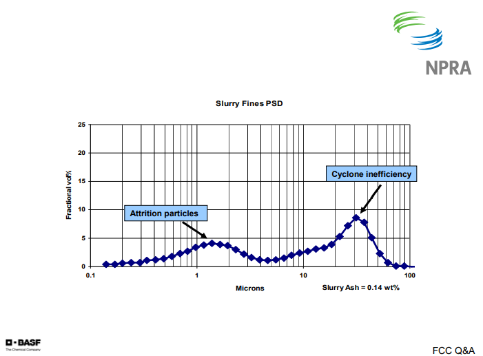
On the following chart, I have a graph of the particle size distribution. What you see here is a typical bi-modal distribution of the fines. The first peak, or the left peak, shows the attrition products that are typically in the 1 to 2 micron range. The second peak, or the right peak, is typically the cyclone losses or inefficiencies. That is generally going to be in the 15 to 30 micron range.
THOMPSON (Chevron)
Typical ash content for various RTDs range from 0.005 to 0.2 wt%, with most in the 0.05 to 0.1% range. We use ASTM D-482 for figuring ash content. We do not run particle size distributions on the fines, but one technique we found particularly helpful for troubleshooting is photomicrography. That is where you basically take your sample, lay it out, and take a photomicrograph so you can qualitatively look at the particles. We have found that it has been very helpful for understanding what the material is that we are capturing.
For units that have to meet stringent ash content specifications, we have used slurry settlers, filters, ESPs, and various other devices. In our experience, they are all maintenance headaches. We have had problems with filter plugging due to asphaltenes and waxes in at least one location. The other problem is that you generate a backwash stream that has to be dealt with in the riser with your feed nozzles and that can result in fouling and coking.
WALKER (UOP)
Catalyst losses are a function of the RTD design, the equipment-induced catalyst attrition, and the fines entering with the fresh catalyst. For ultra-clean feeds, the unit could need as low as 0.1 to 0.12 pounds of catalyst per barrel of feed. At this level of catalyst makeup, a good RTD will lose about 0.01 to 0.02 pounds of catalyst per barrel of feed. However, for ultra-clean feeds, the slurry yield will also be very low. This will drive up the ash concentration.
Slurry ash concentrations under 0.1 wt% are common for clean feeds. We recommend sampling and analyzing the ash and PSD monthly. This information will serve as baseline data for future troubleshooting. Filtration or chemical settling agents can be used to produce ash concentrations for the carbon black products spec, which is, I believe, 500 ppm.
WARDINSKY (ConocoPhillips)
I guess a word of advice: If you are looking at a system to remove fines from slurry, other than a settling aid and a tank, you are going to have to go somewhere with that concentrated stream. We would not recommend that you recycle it back to the unit unless they are short on heat balance because then you are putting all of those fines back out the regenerator side and that may cause problems in the PM removal equipment on the regen side.
The other thing you do not want to do if you have an expander is to route that material back to the riser, because then you are, again, passing those fines back over your expander. The coking folks would probably disagree; but I think from an FCC perspective, I would like to see these streams sent to the coker.
Question 49: In the past year, a sulfuric alkylation unit released a significant amount of sulfur dioxide to atmosphere when light hydrocarbon flowed from the reaction zone through the acid blowdown system and into the spent acid tank. What measures do you recommend for preventing this?
MULLINS (Marathon Petroleum)
Okay. Well, there’s some S02 present in the system. The likelihood is high that the release contains significant amounts of atomized sulfuric acid: the sulfuric acid being atomized by the rapidly vaporizing C4s that would have been carried into the spin acid tank. We would recommend ensuring that the acid knockout drum be sized large enough to allow the hydrocarbons to disengage in the drum.
Secondly, it is recommended that the vapor system be sized to handle the release without creating backpressure that would force the contents of the knockout drum into the spin acid tank. And thirdly, we recommend the operating practice of keeping the liquid drained from the KO drum to the spin acid tank closed during normal operation.
HAZLE (NPRA)
Jay.
ROSS (Axens)
This is an example of technology that we do not license, but I’m indebted to our friends at Stratco DuPont for supplying the response to this question. In the normal design, I suppose the main issue here is under upset conditions or de-inventory in the reactor. It is possible that if great care isn’t taken, you can overwhelm even a well-designed system. But in a normal design, I guess that would represent best practices: one that has a system involved with adequate residence time in settling devices where you anticipate the possibility of some hydrocarbon carryover; for example, in the acid separating device, which I think is shown here. This schematic is representative of some of the more modern units that are out there.
Most importantly, perhaps, is the design in the acid blowdown drum, which in older units has sometimes perhaps been neglected. It’s important to have it nitrogen-blanketed in a three-phase separator in order to anticipate both liquid hydrocarbon, as well as the possibility of some light hydrocarbon (LPG) carryover, such that enough residence time is provided for the light hydrocarbons to volatilize and, in fact, leave with the nitrogen and blanketing agent off to a scrubbing system, as this is operated on a flare header pressure.
Then further beyond that, when you do de-inventory and set off to the spent acid tankage, that system should also be nitrogen-blanketed with a scrubber system in place, both to avoid the explosive mixture possibility, with the blanketing and the scrubbing, so that you don’t emit the S02 to the atmosphere. And again, a time when you have to take the most care, perhaps, is during unit shutdown at de-inventory, so as to take careful and proper precautions during the draining of these materials.
HAZLE (NPRA)
Those are the panel responses. It’s time for your questions. As people carry a microphone to you, just raise your hand.
PETERSON (Stratco DuPont)
Randy Peterson, Stratco DuPont. One correction I would like to make about what Greg said is that there could be aerosol of acid out of the tankage. We don’t really believe that this is true. There was a study done and presented about 15 years ago at the NPRA by Quest about how they tried to make sulfuric acid aerosol. In the study, it really was not ever shown to happen. We would see SO2 coming off, but the acid was so heavy and so viscous. So if there was any kind of aerosol, it would drop out very quickly outside of the tank. So an aerosol cloud with sulfuric acid is something we don’t believe is possible.
HAZLE (NPRA)
Thank you. Other comments, questions. There’s one up front.
PROOPS (Solomon Associates)
Kevin Proops with Solomon Associates. We may have to get Randy to help answer this one again. We haven’t talked about layer-of-protection analysis (LOPA), per se, on this, but I’m wondering if Randy or the panelists have comments on instrumentation to help prevent this situation. For instance, was this incident caused by a faulty level transmission from the acid’s alpha settler? Could high pressure in the acid blowdown drum have been sensed and helped prevent undercarry? Are there other potential fixes, or more LOPA that are instrumentation-driven, that are possible?
HAZLE (NPRA)
Jay. No? You’re deferring? Deferring.
PETERSON (Stratco DuPont)
Yeah, I will answer that. I think Jay kind of hit the nail on the head. A lot of units out there that are 30, 40, and 50 years old do not have a lot of instrumentation or the appropriate instrumentation. The newer units do have level controls, and this was a result of not understanding the level controls that they had on the less modern control systems. Yes, a lot of hydrocarbon came to the blowdown drum and was pumped out to the tankage.
In our system, it is a three-phase acid blowdown drum. There’s vapor, hydrocarbon, and acid. And if it’s almost all hydrocarbon and just a little bit of acid, it still shows up as acid in the level gauges. So operators have to understand that with the three-phase drum, you need to have the acid level near the top of the baffle; otherwise, you might be pumping hydrocarbon. If it shows acid to the top of the baffle, then you know that it has to be pretty much acid because acid is three times the density of hydrocarbon. So that’s the LOP. I mean that would have helped in this case.
UNIDENTIFIED SPEAKER
Is there training for this?
PETERSON (Stratco DuPont)
Oh, absolutely. Training is a big thing. Operators tend to forget, maybe, how to properly run these units, and over time—every five years or so—they should be retrained.
HAZLE (NPRA)
Any other comments? Other comments or questions? That was for the tape anyway. That was Randy Peterson, Stratco. Anyone else? Then we’ll move on to Question #50. First response: Clever.
Submitter
Process
Question 50: What is the proper firefighting media to use when putting out a fire when both spent sulfuric acid and heavy hydrocarbon are present (e.g., in a spent acid tank or a diked area that has a layer of hydrocarbon floating on the spent acid)?
Including the volume involved, is it contained or not contained? Is the hydrocarbon contained or not contained on top of the acid? What other exposures are involved or potentially involved? And then based on this assessment, be aware that the best approach may be to let the fire burn out, depending on how much hydrocarbon is involved and how much containment is possible in these other issues.
One thing that was brought home pretty clearly to me was that the best approach is actually to minimize the hydrocarbon inventory. It’s a kind of a housekeeping sequence where frequent skimming minimizes the amount of hydrocarbon that’s on top of the acid. Also, you want to avoid uneven cooling of the tank rim, as it’s very difficult to get that cooled evenly at all, and it can lead to splitting of the rim.
I should mention that we did have one experience, late in a fire, where they were able to use carbon dioxide to extinguish the remaining fire. That would be considered part of the arsenal in future fires.
HAZEL (Tesoro)
This response is based on what I’ve gleaned from our folks that do have sulfuric acid units. That’s a difficult fire to tackle, you know—kind of walking through the process. The water and acid will interact, which makes water a poor choice. Most of the foams of which we are aware are mostly water. A dry chemical will also react to the acid. So, as always, when you get into a fire situation, there’s some initial assessment that’s required of the fire.
HAZLE (NPRA)
LOWE (Pasadena Refining)
When I first asked for help on this question, the person’s initial response was that he would use alcohol-resistant acquiesce film-forming foam. And then in discussions in the panel, as Clever was referring to, there was some experience with this. In this situation, this foam didn’t work very well. They had a lot of breakthroughs in the foam blanket and light-offs after breakthroughs.
So I went back and asked some other people for some help on it and they recommended that maybe 6% foam would have resisted it better, as far as the breakthrough goes. And then they recommended CO2 also; as Clever mentioned, that they had used it successfully. And then I reached way back to someone whom I knew had a lot of experience, and he told me that there is a new class of foam being used in Europe specifically for fuming acid blanketing. He said that it would probably hold up to the acidic situation experience in this type of fire. He also told me that the Coast Guard is running some tests on this foam, but it is being used in Europe right now
HAZLE (NPRA)
Those are the panel responses. Questions from the floor? Other recommendations about film for this kind of situation? Going on, then, to Question #51. First response: Pedro.
Submitter
Question 51: Reforming unit stabilizer column top trays and overhead condensers can experience fouling with ammonium chloride salts, which are commonly removed by online water washing of the column overhead. What practices do you employ to reduce the risk of rapid corrosion and the potential failure associated with this fouling and subsequent water washing procedure?
FERNANDEZ (Jacobs Consultancy Group)
Ammonium chloride salts are a common problem in both naphtha reforming and naphtha hydrotreating units. This has been discussed several times in previous NPRA Q&A panels. The problem tends to be the reactor effluent condenser; the inlet to the recycle gas compressor; and the position of the product stabilizer. We’ll talk here mostly about the product stabilizer issues.
A quick review of the basics is important to understand where they come from and the origins of these salts. Ammonium chloride salts are formed because of the presence of both ammonia, hydrogen chloride, and hydrogen in the reactor effluent stream. These two combine to form the salt and precipitate. A relevant number to remember is how little nitrogen in the feed you need to have in order to have the potential of making very large amounts of salt. If you have a 20,000 BPD semi-region or CCR naphtha-reforming unit, and the feed to the unit has .5 wt ppm nitrogen, that nitrogen has a potential to convert itself in 4700 pounds of ammonium chloride salt. And if you think about this, that’s about 100 sacks of 50 pounds of salt. So it is a large amount of salts that can accumulate. An often-misconceived idea comes from the fact that these only deposit in cold sections of the unit.
As this chart shows, you can have precipitation in very warm sections of the unit, up to 300° F. It all depends on what is the concentration of both the ammonia and the hydrogen chloride. The biggest concern about these deposits is not only the nuisance of having things plugged inside your units, but also the facts that these salts are very hydroscopic; they absorb water; and the water that pools around these salts tends to form a very acidic and corrosive solution. And if you leave it behind, you will have a great potential for under-acid corrosion in the areas where you have these deposits.
In order to prevent the formation of ammonia chloride, we think the first medicine is always to avoid it: Don’t have it there. What you need to look at are the sources. Obviously, you cannot completely eliminate the hydrogen chloride from your system. It’s part of the reforming catalysis, so you will always have hydrogen chloride coming out in the reactor. What you can try to do is avoid the ingress of nitrogen and the feed to the unit.
When you talk with most licensers, they recommend that you have less than .5 wt ppm nitrogen in the feed-to-reforming unit. We think that that is the basic—what we would call basic standard of care. We would recommend going lower. We know several refining customers that actually have a standard that says that the nitrogen feed should be lower than .2, and we would encourage everyone to try to meet this standard at least. We realize that’s pretty easy to say when you’re processing straight-run naphthas from sweet crudes, but it might not be possible to do when what you’re processing is thermally-cracked naphthas, coker naphthas, and the like.
There are some occasions that you really cannot avoid the nitrogen coming in the units. You then have to go to the second line of defense, which is looking at what else you can do to avoid the formation. There are two techniques that have been used to avoid the formation of ammonium chloride salts in the stabilizer, and they come by trying to scavenge the chlorides coming out of the reactor before they get to the product stabilizer. The most common system used is to—[end of Side __, Tape __]
UNIDENTIFIED SPEAKER
We might have been the ones who submitted this question. It’s a two-parter, so I’ll address them both. One of our refineries that has a sulfuric acid alkylation unit is currently not operating the system under a vacuum. We were interested in doing this because between runs, if you want to get more out of your compressor and your section piping isn’t big enough, then that’s the next option. I was hoping to get a test run in before the meeting, but we didn’t get a chance to do that. As far as the bottleneck and refrigeration section, we’ve installed the larger driver and refrigeration compressor, added compressor discharge cooling, optimized the refrigerant composition, and installed the larger effluent recycle pumps.
HAZLE (NPRA)
Clever.
HATZEL (Tesoro)
Tesoro has no experience running less than atmospheric with this compressor, but some suggested aids were to use chillers to cool the refrigerant or the depropanizer bottoms recycle stream. Also mentioned were just lowering the contact temperature with the aid of a chiller as well. Then the usual kind of de-bottlenecking approaches can replace suction, specifically, but potentially also discharge lines that are around the compressor. Can you increase the capacity of the compressor to move the refrigerant around?
HAZLE (NPRA)
Those are the panel responses. Has anyone in here tried to run a compressor at negative suction pressure? Any other questions on this topic? We’ll go on to Question 52.
Submitter
Process