Question 22: With the introduction of modern riser termination devices (RTDs) and the advent of severe FCC feed hydrotreating, what is your experience (typical values) with the ash content of the main fractionator bottoms (MFB) product? Please describe the testing methodology utilized and the recommended testing frequency for this stream. What process, practices, and/or equipment changes can be employed to reduce the ash content of the MFB product?
ASDOURIAN (Sunoco Inc.)
Sunoco’s FCCs operate primarily in resid cracking mode; either atmospheric or vacuum resid, typically without the benefit of upstream feed hydrotreating. We have FCCs with coupled two-stage riser termination devices, riser cyclones uncoupled to the secondaries, and simple RTDs followed by either single- or two-stage cyclones.
Depending on the unit and the length of the run into the cycle, our ash contents range from 0.05 up to 0.4 wt%. We have also observed that the ash content varies with the amount of fresh catalyst addition rates and the Main Fractionator Bottoms yields.
The Main Fractionator Bottoms stream was typically analyzed by the refinery laboratory three times a week for BS&W. Ash content and the analyses are performed with respect to the appropriate ASTM protocol. BS&W measurements tend to be higher than the ash results, as expected. The Main Fractionator Bottoms stream is also submitted to our catalyst supplier for a particle size distribution on a monthly basis.
Particle size distribution from the coupled two-stage riser operation tends to show only less than 40 micron particles, with the average in the mid-20 micron range. Other systems tend to show larger particles that should have remained within the circulating inventory. The simplest systems have an average particle size in the 30 to 40 micron range.
We have worked with our process chemical suppliers to evaluate various slurry-settling aids to facilitate ash reduction where necessary. Generally, we found settling aids to be effective when utilized.
HEATER (BASF Catalysts)
Typically, an RTD will allow higher severity and conversion within constraints, resulting in lower slurry yield. Severely hydrotreated feed also reduces slurry yield. Both result in higher catalyst circulation and typically somewhat higher losses. However, the lower slurry yield will concentrate any catalyst losses on the reactor side.
For a well-designed cyclone system, ash should be less than 0.1 wt%. Dropping LCO into the slurry is done, but obviously it is not a good economic alternative. As Aram mentioned, the catalyst supplier will typically analyze slurry for ash and particle size distribution. Once per month is usually adequate.
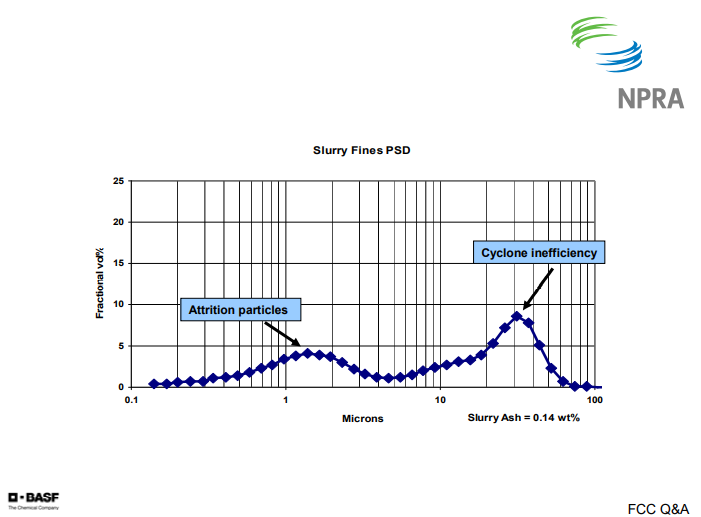
On the following chart, I have a graph of the particle size distribution. What you see here is a typical bi-modal distribution of the fines. The first peak, or the left peak, shows the attrition products that are typically in the 1 to 2 micron range. The second peak, or the right peak, is typically the cyclone losses or inefficiencies. That is generally going to be in the 15 to 30 micron range.
THOMPSON (Chevron)
Typical ash content for various RTDs range from 0.005 to 0.2 wt%, with most in the 0.05 to 0.1% range. We use ASTM D-482 for figuring ash content. We do not run particle size distributions on the fines, but one technique we found particularly helpful for troubleshooting is photomicrography. That is where you basically take your sample, lay it out, and take a photomicrograph so you can qualitatively look at the particles. We have found that it has been very helpful for understanding what the material is that we are capturing.
For units that have to meet stringent ash content specifications, we have used slurry settlers, filters, ESPs, and various other devices. In our experience, they are all maintenance headaches. We have had problems with filter plugging due to asphaltenes and waxes in at least one location. The other problem is that you generate a backwash stream that has to be dealt with in the riser with your feed nozzles and that can result in fouling and coking.
WALKER (UOP)
Catalyst losses are a function of the RTD design, the equipment-induced catalyst attrition, and the fines entering with the fresh catalyst. For ultra-clean feeds, the unit could need as low as 0.1 to 0.12 pounds of catalyst per barrel of feed. At this level of catalyst makeup, a good RTD will lose about 0.01 to 0.02 pounds of catalyst per barrel of feed. However, for ultra-clean feeds, the slurry yield will also be very low. This will drive up the ash concentration.
Slurry ash concentrations under 0.1 wt% are common for clean feeds. We recommend sampling and analyzing the ash and PSD monthly. This information will serve as baseline data for future troubleshooting. Filtration or chemical settling agents can be used to produce ash concentrations for the carbon black products spec, which is, I believe, 500 ppm.
WARDINSKY (ConocoPhillips)
I guess a word of advice: If you are looking at a system to remove fines from slurry, other than a settling aid and a tank, you are going to have to go somewhere with that concentrated stream. We would not recommend that you recycle it back to the unit unless they are short on heat balance because then you are putting all of those fines back out the regenerator side and that may cause problems in the PM removal equipment on the regen side.
The other thing you do not want to do if you have an expander is to route that material back to the riser, because then you are, again, passing those fines back over your expander. The coking folks would probably disagree; but I think from an FCC perspective, I would like to see these streams sent to the coker.