Coffee Break
Session Start End
-
WATKINS [Advanced Refining Technologies (ART)]
Arsenic is a big concern because it is a permanent poison that causes fairly significant activity. We generally see around a 60° Floss per weight percent pickup; so you will want to pay attention to it. As a side note, it is also common in most fractions of hydrotreating: so anything from naphtha to heavy gas oil. Since there are a large number of process variables, catalysts, and operating conditions, the level that would define where a dedicated trap is actually needed will really depend on how much arsenic is coming into your reactor and possibly what other catalyst is present there as well. Generally, we like to monitor how many pounds of arsenic per day are coming into your hydrotreater; then, we look at the controlling mechanisms for deactivation.
The chart on the left side of the slide compares relative arsenic pickup on the catalyst to the actual amount of nickel present in the reactor. One of the major factors for how much arsenic your reactor can hold is how much nickel is sitting at the top of your reactor, or even in the whole reactor. So, as you go from left to right, you can see you can pick up quite a bit more arsenic.
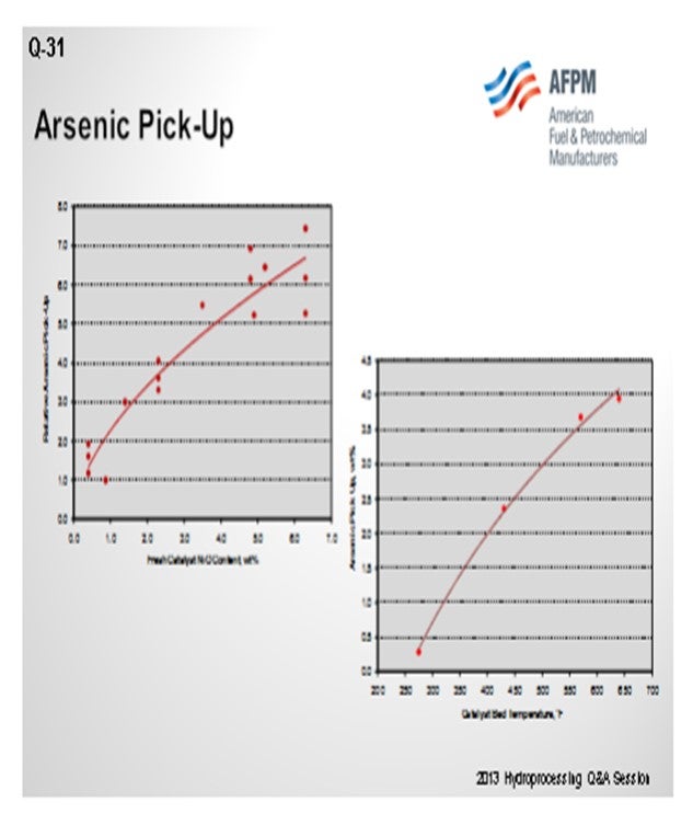
What also controls arsenic pickup is the operating temperature of your hydrotreater. You can generally look at the weighted average bed temperature or the actual temperature of where the catalyst is located. Something like a diolefin reactor down at 250°F to 300°F will pick up a very low level of arsenic. Whereas if you get up into the 650°F to 700°F range, that same catalyst can pick up a significant amount if it is in the right location. So, these two factors will really define how much volume we need to place, in terms of a guard catalyst in your reactor.
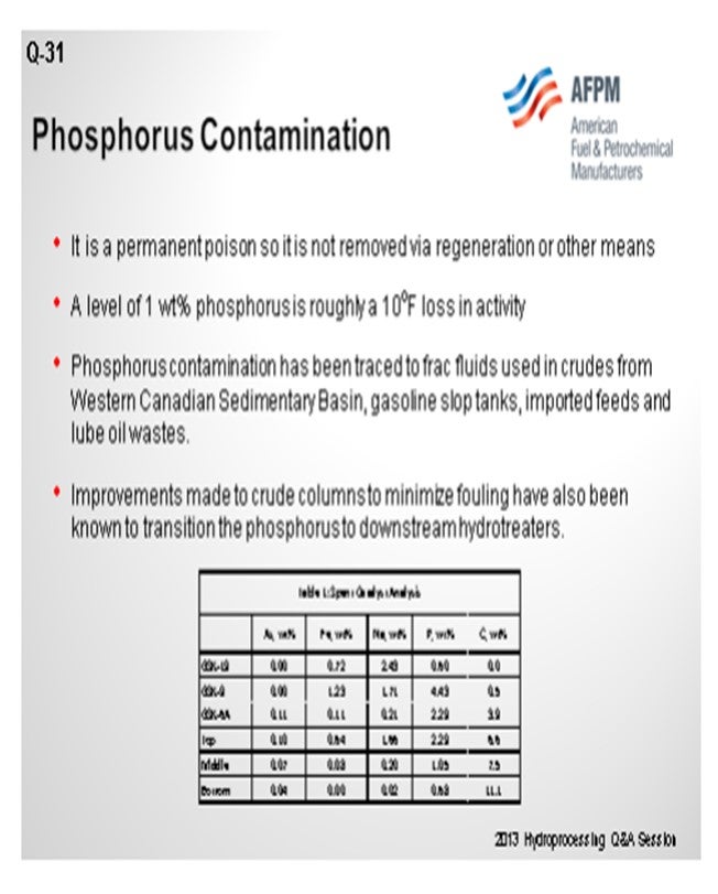
With phosphorus, there is the same problem. In this case, at about 1 wt% (weight percent) pickup, we see somewhere in the order of 10°F loss in activity. That number goes up as you get significant levels of phosphorus on the catalyst, but the first amount is not necessarily as important. On the bottom of the slide is a table showing a spent catalyst analysis from a reactor. You can see that this unit was able to pick up phosphorus even on some of our guard material. So, in some of our rings and support, you can actually pick up quite a bit of phosphorus. Again, that is related to temperature. It is also related to alumina surface area, similar to silicon trappings. So that should be your focus. Really, the amount of catalyst in your hydrotreater will determine where you define your need for dedicated trap material. We recommend spent catalyst analysis for looking at things like that.
SIVADASAN (UOP LLC, A Honeywell Company)
Arsenic is a poison for hydroprocessing catalysts and tends to be specific to crude sources. We have seen that how they apply to catalysts is mainly determined by the type of reactions being carried out. So for example, in a ULSD (ultra-low sulfur diesel) unit, if you see where an indirect hydrogenation route is the preferred part, then concentrations as low as 500 to 1,000 ppm (parts per million) of arsenic can affect the activity of the catalyst by more than 50%. But in a unit that is processing around 500 ppm of diesel, the catalyst will be able to withstand up to 1 wt% of arsenic before you see a 50% reduction of the life. Due to the broad range of arsenic concentrations, electro, and cycle lengths, we believe that it is not possible to confidentially cite a specific threshold concentration above where its dedicated arsenic trap system may be required.
Phosphorus, again, can enter into the hydrotreater unit from various sources like crudes, drilling fluids, and phosphated trendsetters. They are the same biofeeds. We believe that the phosphorus generally tends to be quite similar to the sodium. Around 1 wt% of sodium may affect the activity of the catalyst by more than 50%. The catalyst performance and maximum allowable limit are highly dependent on the source and form of the phosphorus.
MUKESH PATEL (Reliance Industries Ltd.)
What is the Best Practice for analyzing arsenic and phosphorus? Should it be done weekly or on some other frequency? Because arsenic is very important when the crudes are changing every now and then, what should be the frequency and what is the industrial experience?
SIVADASAN (UOP LLC, A Honeywell Company)
The determination of arsenic is a bit difficult, as you pointed out, because it interferes a lot with the lab analysis. What people generally do is run a cycle, do a spent catalyst analysis, and then back-calculate how much amount of arsenic is in the feed.
MUKESH PATEL (Reliance Industries Ltd.)
When we say spent catalyst analysis, it is some sort of analysis of used catalyst, right? But what is a better predictive estimate we can do? Because when you want to capture, you can decide on some limit on the arsenic and then put in an arsenic trap. But if you keep putting on an arsenic trap, you will ultimately have a challenge because you will be compromising on cycle life. What I mean to say is that spent catalyst analysis is done after the completion of the cycles, which tells you what the true level of arsenic was in your feed. For example, suppose you are deciding about some loading for the new cycle and how to capture arsenic. Once you start putting in more and more arsenic traps or any demetallizing catalyst, you will be compromising the cycle because your volume will be less in the main catalyst. So, has there been any development where the conventional arsenic traps have a certain capacity for absorbing the arsenic? Is there any new development to help us capture three or four times the arsenic with the same type of volumes?
WATKINS [Advanced Refining Technologies (ART)]
The amount of trap will really depend on your main bed catalyst and your guard catalyst up at the top. If using a high-nickel catalyst, you could actually trade off and balance that activity; so you will maximize your cycle. If you have nickel catalyst in your entire reactor, you could extend your cycling because you can actually pick up a lot more arsenic that way. It is a constant battle, though, to define your cycle length and the amount of arsenic you can pick up. It is all dependent on temperature and how many pounds per day you are going to put in. I recommend that you work with your catalyst supplier to figure out an optimum system and what their products can actually hold without losing any activity or cycle length.
BRIAN WATKINS [Advanced Refining Technologies (ART)]
Arsenic
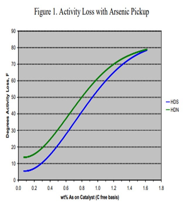
Arsenic (As) is found in many crudes including some from West Africa and Russia, as well as many synthetic crudes. It is becoming a common contaminant as use of these crudes, especially synthetic crudes, has been increasing in recent years. The arsenic is believed to bind with the metal sulfide sites (and in particular, the active nickel on the catalyst) forming nickel arsenide. This has a dramatic impact on catalyst activity. To demonstrate the effect of arsenic on catalyst activity, ART obtained a series of spent catalysts containing different levels of arsenic. These samples were carefully regenerated in the laboratory and were then activity tested using a diesel feed containing 50% cracked stocks under conditions producing less than 500 ppm sulfur. Figure 1 summarizes the results of that work. At 1,000 ppm, arsenic on the catalyst shows 5°F HDS (hydrodesulfurization) activity loss and nearly 15°F loss in HDN (hydrodenitrogenation) activity. The activity loss quickly increases to over 50°F with 1 wt% arsenic on the catalyst.
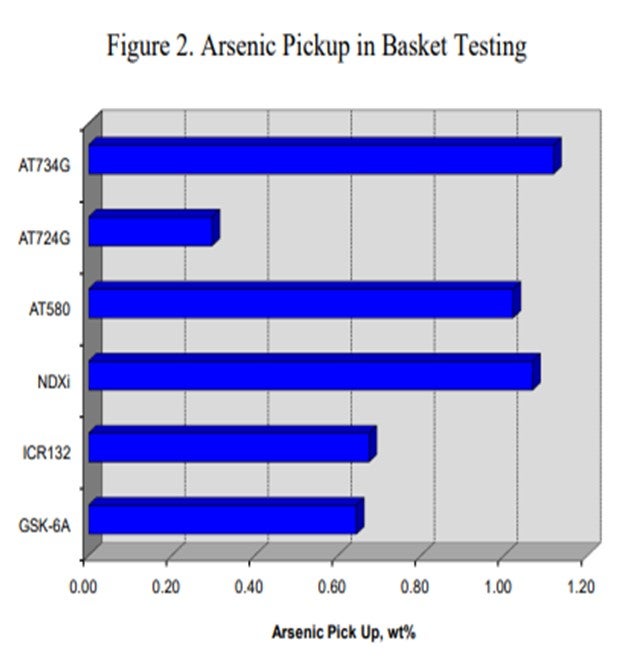
Canister data for a variety of catalysts also indicates that catalysts containing nickel are more effective for trapping arsenic. Figure 2 summarizes the arsenic pickup values for several NiMo (nickel molybdenum) catalysts. As this data shows, both high metals ULSD catalyst NDXi and AT580 as compared to our recent guard catalysts AT724G and AT734G, which are quite effective for trapping arsenic. The data also indicates that the active ring materials and demetallization catalysts used are also effective for trapping arsenic.
Other canister data also shows that the ultimate arsenic pickup is heavily dependent on temperature. Figure 3 shows the arsenic pickup as a function of temperature for a NiMo catalyst. These results were obtained by analyzing spent samples of a high metals NiMo catalyst from a three-reactor unit processing 100% cracked naphtha from a synthetic crude source. The first reactor was operated at very low temperature (about 275°F) in order to saturate diolefins. The second reactor was designed to saturate mono-olefins and operated at about 430°F. The last reactor had an inlet of 570°F and an outlet temperature of approximately 650°F. The arsenic content on the catalyst correlated with the temperature of the reactor as depicted in the figure. The data demonstrates that a high nickel catalyst can pick up very high arsenic levels if the operating temperature and feed concentration are high enough.
Noting that there are a wide range of arsenic levels, unit operating conditions, and expected cycle lengths, the ability to define a single-set threshold for when a trap is needed is difficult. It is recommended that if arsenic is found to be a problem contaminant, you will need to consult your supplier to determine if it is impacting the cycle and if and how much guard catalyst is needed.
Phosphorous
Phosphorous contamination in oil has been traced to fracturing fluids that are often used in crudes from the Western Canadian Sedimentary Basin. The source is diphosphate esters which are soluble in the crude oil. Refineries that run large percentages of light Western Canadian crude have reported crude column and crude furnace fouling for many years. Improvements made to crude columns to minimize fouling have transitioned the depositing of phosphorous to the downstream hydrotreaters.
Other sources of phosphorous include gasoline slop tanks, imported feeds, and lube oil wastes. If phosphorous does manage to make its way into the hydrotreater, it will poison the active sites of the catalyst causing a loss in activity. A level of 1 wt% of phosphorous on the catalyst results in roughly 10°F loss in activity. ART recommends that a feed content of less than 0.5 wppm (weight parts per million) be maintained whenever possible, as well as the use of feed filters to assist in trapping of phosphorous sediment.
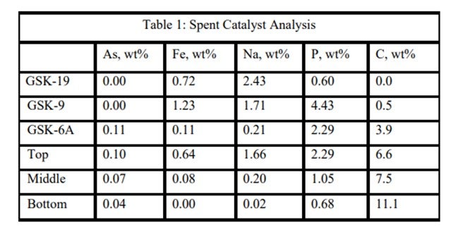
An ART catalyst case study of the detrimental impacts of feed poisons on hydrotreater performance involved a ULSD unit which had recently started up with ART catalysts. Shortly after startup, the unit began to experience extremely rapid catalyst deactivation. It was so severe that within a couple months, the unit required an unplanned turnaround and the installation of fresh catalyst. Samples of spent catalyst representing the whole catalyst charge were collected and analyzed in the laboratory. The results are summarized in Table 1. It is apparent from these results that the catalysts were exposed to high levels of several poisons including arsenic, sodium, phosphorous, and iron. The contaminants penetrated well into the catalyst bed. Catalyst at the bottom of the reactor was not yet poisoned, but the coke content was extremely high for catalyst which had been onstream such a short time. The level of contaminants indicates the catalyst in the top half of the bed lost over 60°F of activity while the bottom was providing most of the HDS conversion. This required very high temperatures, which is reflected in the high carbon content at the bottom of the bed.
ART has a suite of options in order to protect the main bed from these and other contaminants which may be present in the feed to a typical hydrotreater. The use of several of these materials combined together can adequately provide protection and extend the cycle life of your hydrotreater.
RAJESH SIVADSAN (UOP LLC, A Honeywell Company)
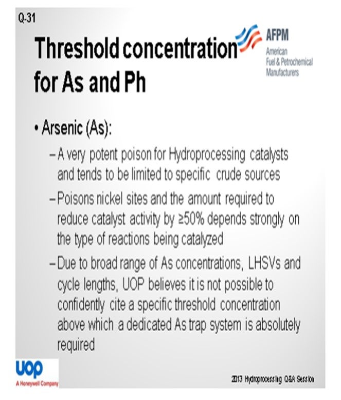
Arsenic (As) is a very potent poison for hydroprocessing catalysts. Although As tends to be limited to specific crude sources (e.g., crudes from the U.S. and Canadian Rocky Mountains, Russian Urals, specific Chinese and West African sources, and “synthetic crudes” from Canada and Venezuela), it is usually present in all boiling fractions of those crudes.
Arsenic tends to poison the nickel sites of hydroprocessing catalyst, and the amount required to reduce catalyst activity by ≥50% depends strongly on the type of reactions being catalyzed. For instance, in diesel hydrotreating where ULSD is produced and product quality depends heavily on hydrogenation route desulfurization, as little as 500 to 1,000 wppm arsenic on catalyst can reduce HDS activity by 50%. On the other hand, for hydroprocessing applications where direct desulfurization is the primary mechanism for reaching product targets, higher levels of arsenic contamination on catalyst (about 1 wt% As) may be tolerated while retaining HDS activity greater than 50% of fresh catalyst activity.
Because of the broad range of as concentrations on catalyst that will poison the catalyst, as well as the broad ranges of LHSVs (liquid hourly space velocities) and cycle lengths for various hydroprocessing applications, UOP believes it is not possible to confidently cite a specific threshold concentration for as in feed above which a dedicated as trap system is absolutely required.
Phosphorus (P) can enter the hydrotreater feed from numerous sources: crudes, drilling fluids, phosphated ZSM (Zeolite Socony Mobil), phosphorus-based corrosion inhibitors and flow improvers, and biofeeds.
In one UOP commercial experience, about 3 wt% phosphorus on the catalyst terminated all the exotherm in the catalyst bed. Organic phosphorous can penetrate into catalyst pores. In general, our understanding is that the poisoning is similar to sodium where about 1.0 wt% concentration reduces the catalyst activity by 50%.
Based on UOP’s experience, we have found that the quantitative effects of phosphorus on hydroprocessing catalyst performance and the maximum allowable level are highly dependent on the source and form of the phosphorus compound, catalyst properties, and the process application, which all need to be considered when designing a trap system. Thus, UOP believes it is not really possible to confidently cite an absolute threshold concentration for phosphorus in feed above which a dedicated trap system is definitely required.
PER ZEUTHEN (Haldor Topsøe, Inc.)
Arsenic and phosphorous compounds are both known as permanent catalyst poisons; however, they each have very different deactivation mechanisms. Arsenic species found in the crude oil, particularly in the heavy ends, act as a true catalyst poison during titration of the nickel- or cobalt-promoted catalytically active sites. Although the concentration typically is rather low in ppb (parts per billion) levels, content of more than 50 ppb, for example, will have a significant negative impact on the catalyst performance. Arsenic compounds are very poisonous to the working catalysts, a typical high-activity catalyst has lost most activity after accumulation of as little as 1% As. Besides, shale oil and other new crude types (Russian and Canadian crudes) contain significant arsenic levels.
Haldor Topsøe has developed a number of dedicated arsenic pickup catalysts to protect the downstream bulk catalyst from very severe poison. The arsenic pickup capacity of this catalyst, TK-45, is as high as 10 wt%, but the actual pickup capacity will depend on the arsenic level in the feed and the operating temperature. With improved diffusion and preparation, Topsøe has recently launched a new dedicated arsenic trap, TK-49, with improved arsenic pickup for all hydrotreating applications.
Phosphorous species are rarely found in typical crudes; however, some opportunity crudes (and in particular, renewable feeds) often contain significant amounts of phosphorous. Moreover, phosphorous containing anti-corrosion additives can be found in the diesel and VGO (vacuum gas oil) fractions. The phosphorous compounds are decomposed in the hydrotreater, and the phosphates react with the alumina support, forming very stable alumina phosphates. Accumulated amounts of phosphates will reduce the accessibility to the active sites of hydrotreating catalysts and lower the activity accordingly.
Topsøe has a specialty product, TK-31, with a capacity of more than 5 to 6 wt% phosphorus, where reaction sites for phosphates have been improved the most. Topsøe recommends installing this phosphorous trap if the feed level is higher than 2 ppm phosphorus for protecting the downstream bulk catalyst from contamination.
WATKINS [Advanced Refining Technologies (ART)]
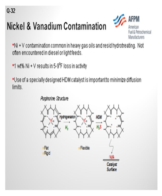
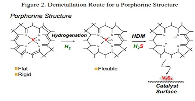
Nickel and vanadium contamination generally come in heavy gas oils and resid hydrotreating. It is obviously not very common in diesels and light feeds. We see that it is about a 5°F to 9°F loss per weight percent combined pickup. The reason you will want to pay attention to these metals is because of their ability to actually diffuse onto the catalyst, so you will need a space to deposit them. Nickel and vanadium are generally tied up in these large porphyrin-type structures. They are fairly rigid and not easily accessible. They also require some level of saturation to be able to get out that nickel and vanadium in order to actually have it react on the catalyst surface. So, you really need not only a space to fit this large molecule, but you also need space to then put the nickel or vanadium onto the catalyst surface.
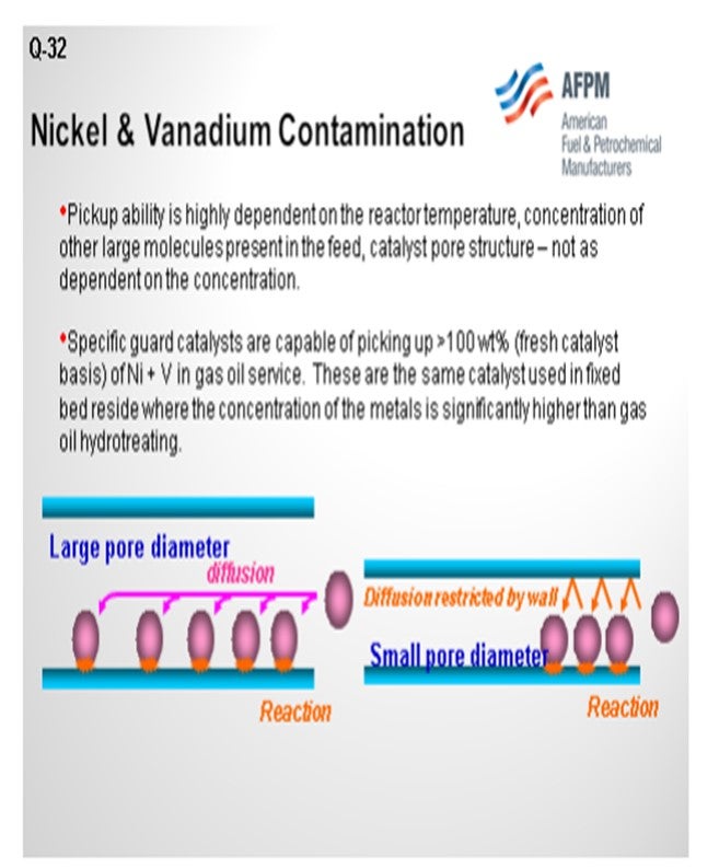
The next slide shows the comparison of a large pore diameter catalyst with a small pore diameter catalyst. With a large pore diameter, you actually can get more metals onto the surface because you are not diffusion limited. Being overwhelmed actually defines the fact that you may have a catalyst that has too small of a pore diameter. You can only get a few metal molecules in on the outside, and then you have basically covered over the available pore volume space. This is highly dependent on reactor temperature: the hotter your reactor, the more metals you can pick up. You can force diffusion into the catalyst pellets, but it can also be indicative of other molecules or poisons present that would help overwhelm the catalyst. Generally, there are specific guard catalysts found in hydrotreating. A lot of them used in resid service are also used in FCC (fluid catalytic cracking) pre-treat, hydrocracker pre-treat. They pick up greater than 100 wt% of nickel plus vanadium, which is why they are generally used. They can pick up quite a bit of nickel-vanadium and not be overwhelmed. So, a properly defined system should prevent being overwhelmed.
SIVADASAN (UOP LLC, A Honeywell Company)
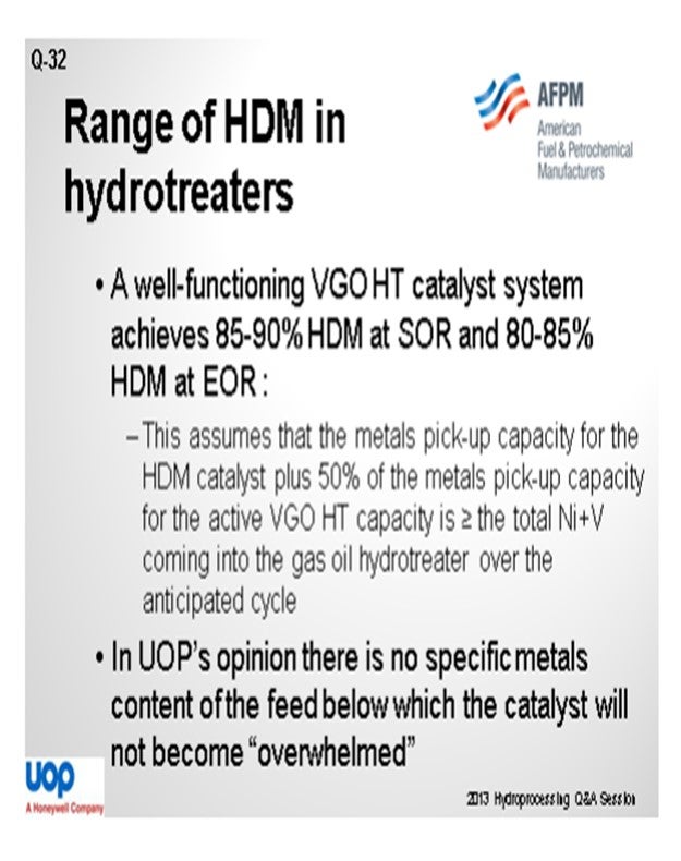
A well-functioning VGO hydrotreating system can do an HDM function of 85 to 90% for start-of-run conditions and 80 to 85% for end-of-run conditions. This is based on the assumption that the metal’s pickup capacity for the HDM catalyst, plus 50% metals pickup capacity of the active VGO catalyst, is more than the total nickel to the nickel plus vanadium which is coming into the unit over the anticipated cycle. In our opinion, there is no specific metals content of the feed below which the catalyst will not become overwhelmed.
BRIAN WATKINS [Advanced Refining Technologies (ART)]
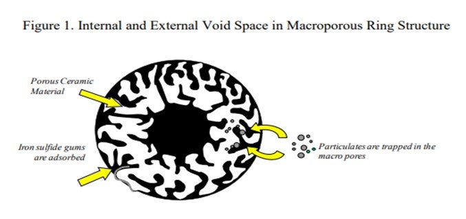
Traces of nickel (Ni) and vanadium (V) are present in most crudes although the amount is strongly dependant on crude type. They are concentrated in the heavier fractions, especially the bitumen and vacuum residue. Ni and V poisoning can be a significant problem in FCC pre-treat and hydrocracker pre-treat units which process heavier feeds, and they are not often encountered in diesel or lighter feeds. The primary deactivation mechanism of these poisons is pore mouth plugging (Figure 1).
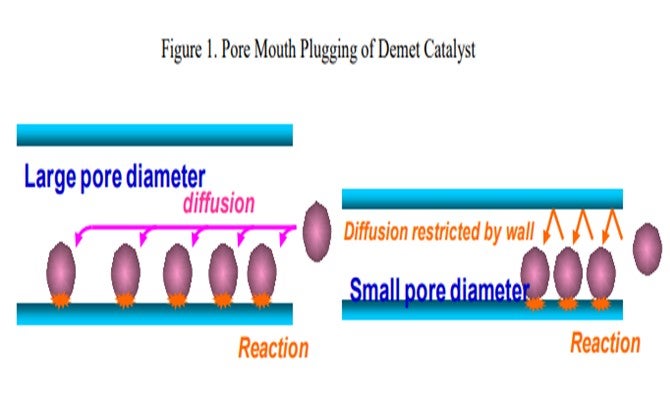
Nickel and vanadium are usually contained in large asphaltene-like molecules which are too large to penetrate into the pores of typical hydrotreating catalysts. Therefore, the nickel and vanadium end up depositing on the outside of the catalyst, ultimately blocking access to the active sites within the pores. Pilot plant testing with heavy feeds on a widely used FCC pre-treat catalyst suggests that 1 wt% Ni+V on the catalyst results in 10°F loss in activity. The activity loss will be greater for a smaller pore (diesel type/grade) catalyst (Figure 2).
Dealing with nickel and vanadium requires specially designed catalysts for removing and storing the metals. These catalysts have very large pore size distributions which are tailored to provide very high capacities for nickel and vanadium.
There are demet catalysts available today that are capable of picking up as much as 100 wt% (fresh catalyst basis) Ni+V in a gas oil hydrotreater. Much like other contaminants, the ability to pick up these metals is highly dependent on the reactor temperature, as well as the concentration of Ni+V coming in with the feed. Generally speaking, if there is a sudden large spike in Ni+V in the feed there are other changes to the feed accompanying this (i.e., increased endpoint) that may be more detrimental to the catalyst performance.
The catalysts typically used for HDM in a gas oil hydrotreater are similar to the ones used in fixed bed resid hydrotreating where the concentration of metals is significantly higher than that found in gas oil hydrotreaters. The main bed catalysts for FCC pre-treating and hydrocracker pre-treat are generally tolerant of some level of these poisons without significant activity loss and can handle short periods of higher Ni+V levels. However, the capacity of these catalysts is typically around 10 wt%, give or take. So, if it is anticipated that Ni+V levels may fluctuate significantly, use of a demet catalyst is generally a good idea.
DAVID VANNAUKER (Haldor Topsøe, Inc.)
The HDM in a gas oil hydrotreater is a function of pressure, temperature, residence time (LHSV), catalyst, and feed. In commercial units, the metals pickup may range from a low of 50% up to 99+%. Operating pressures are fixed in commercial units; but in general, the higher pressure units have improved kinetics. The key variables for optimized metals pickup are temperature, residence time, and the proper catalyst with an optimized pore size distribution. Increasing the operating temperature and residence time provides an increase in the kinetics and removal rates. Catalyst selection, as mentioned, is a key to cycle optimal metals pickup. Demet catalysts have been specially designed to remove metals. The difference between modern demet catalysts and older generation hydrotreating catalysts can be as much as a factor of 6 in performance. Feed endpoint is also a consideration. The metals found in the lighter gas oils can be removed with relative ease. As the feed endpoint is increased, the molecular complexity increases, making the metals removal more difficult.
The HDM functionality can decline very rapidly when the catalyst system reaches the saturation level. Monitoring feed and product metals levels throughout the cycle are both key to avoiding surprises. We are aware of one unit that, about 15 years ago, had metals removal in excess of 90%, which dropped to a level of 50% in less than 60 days. Ordering and changing the catalyst had to be performed on a rush basis.
We have also observed an apparent slumping in HDM performance with large spikes in metals content. This is typically associated with another upset in the refinery, and part of the loss in performance is due to having significantly heavier molecules with metals going through the unit. Topsøe has designed demet catalysts (TK-719, TK-743 and TK-753) specifically for use in resid service and TK-453 for use in gas oil service. The pore size, pore size distribution, and porosity of these catalysts are optimized for maximum metals pickup in the specific service.
LIOLIOS (DuPont Clean Technologies)
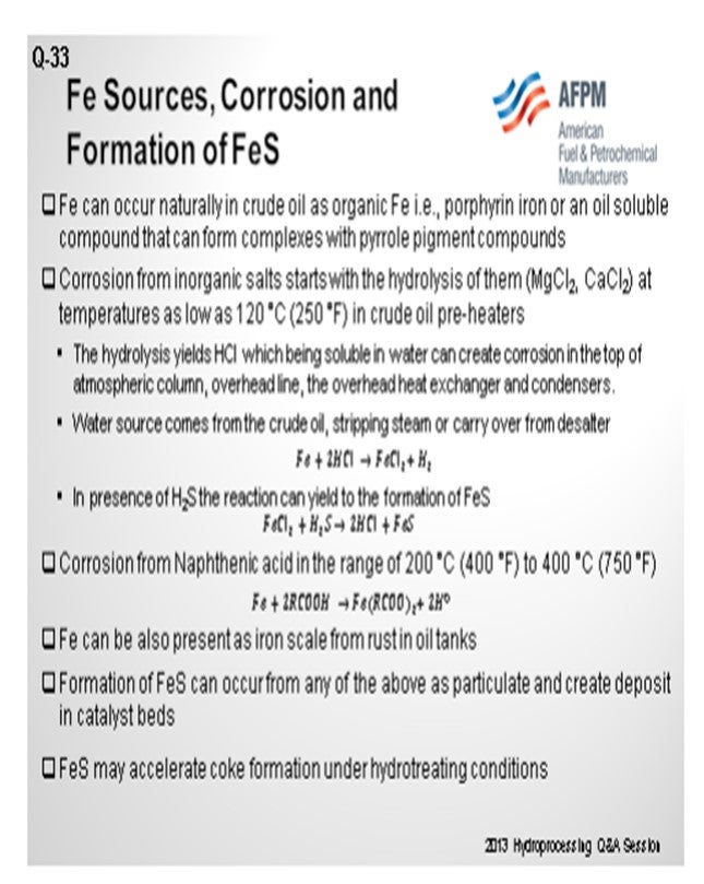
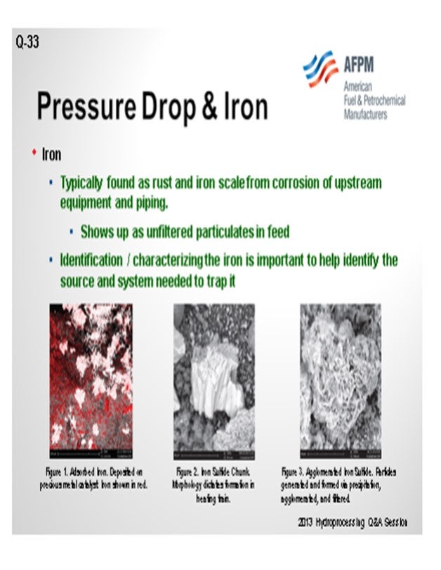
Certainly, identifying the sources of the iron coming in – whether organic, iron oxides, iron sulfides, or just scale from tanks – is very critical to understanding your best strategy for mitigating pressure drop. Ultimately, when you form iron sulfide, it creates deposits on the bed and coke deposition, and certainly leads to reduced catalyst life.
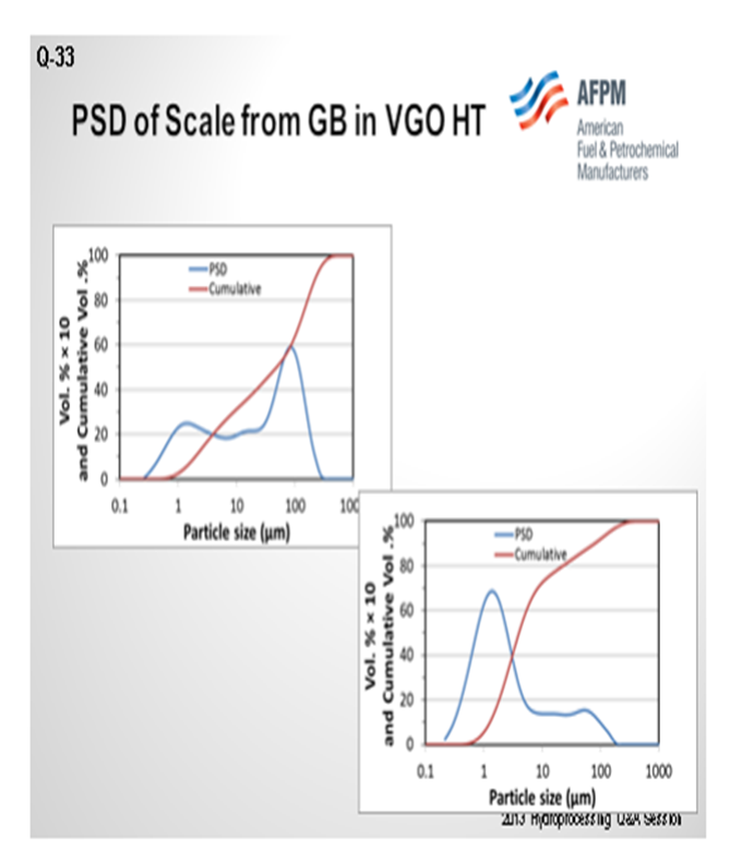
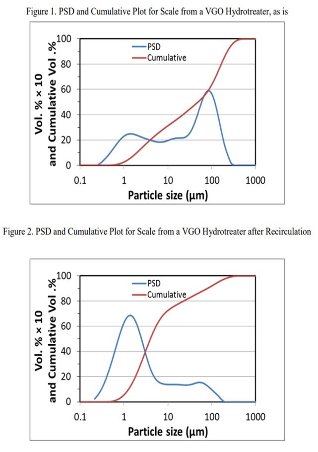
The next slide shows the analysis of the scale that was collected from a guard bed in a VGO hydrotreater. The graph on the left is the first pass on the analyzed scale. About 40% of it was under 25 micron. The analysts took that same sample and re-circulated it. I cannot get into it, but basically 80% of the sample after recirculation was under 25 microns. Also, the small particles will come into your bed under hydrotreating conditions. They will grow and increase in pressure drop, and they will take off on you. Understanding why iron sulfide is coming in and how it is coming in is very important to setting up a strategy, which is shown on the next slide. So, identifying the root cause is important.
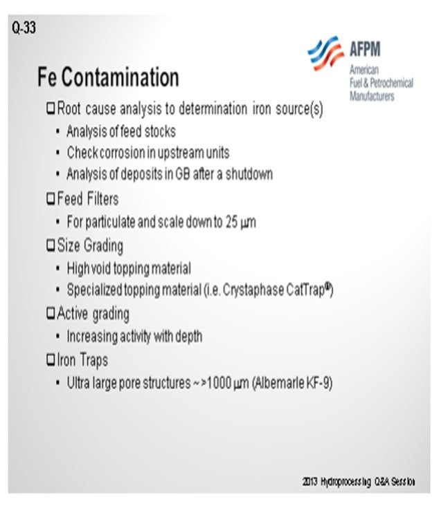
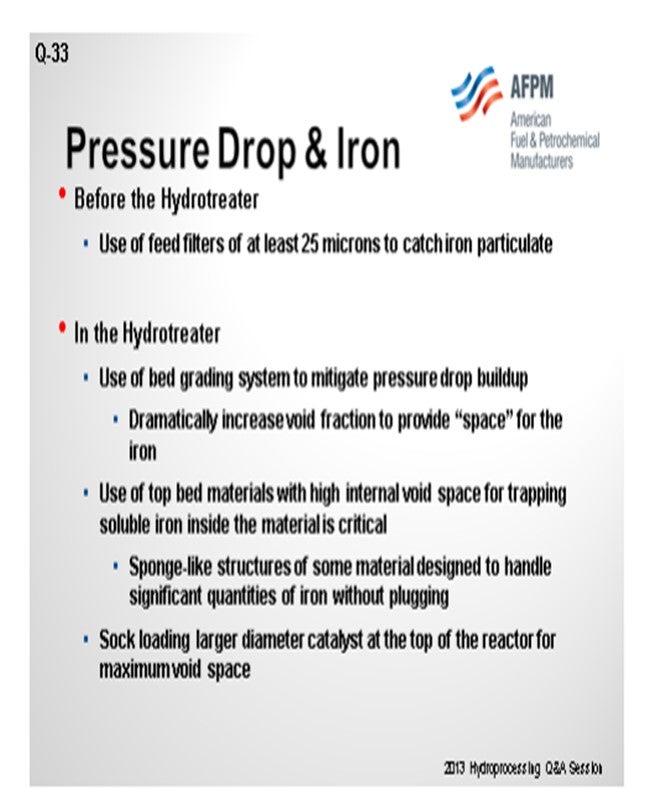
The first phase of the reduction strategy should be feed filtration. Either cartridge or backwash-type filters are most commonly used down to about a 25-micron size. Next, look at size grading, which is a high-void area, in order to capture this material in the void area. Crystaphase CatTrap® or other specialized topping materials are very effective at capturing some of these iron materials then some active grading because some of the iron content will actually form iron sulfide at these conditions. So, after the active grading, you will need additional trapping material with large pore structures in order to capture the iron.
WATKINS [Advanced Refining Technologies (ART)]
I basically agree with a lot of what Glenn just said. The goal is to identify the origin of your iron and determine if there is a way to handle or stop it. If it is corrosion, we can certainly take care of it elsewhere. Characterization is the key. The bottom three pictures on the slide simply show iron and how it is sitting in the reactor or on various places in exchangers or furnaces or on the catalyst. Some can be filtered out; for others, you must use a catalytic mechanism. The one on the left is absorbed iron on catalyst.
Again, 25 microns is the target range for iron-particulate scale and other contaminates that are going to come into the hydrotreater using a grated bed system to mitigate any pressure drop. The goal is to dramatically increase the actual void fraction so you have somewhere to put this incoming iron. Top-bed materials with high internal void space are important. Sock loading: If you know that a prior cycle had a problem, the goal next time may be to change the diameter of your catalysts. Sock-load a portion of the bed so that you have some space, and do not shut down on pressure drop. If you have enough void space in your reactor, the contaminates can sometimes actually pass through. This will not really be a problem in your catalyst beds if you have too much void space.
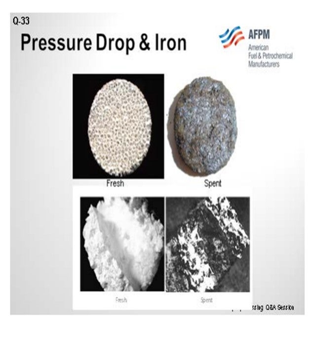
The third slide shows an example you may have already seen. On the top left is a Crystaphase disk, which we can see has a very large void space. You can actually fill up quite a bit of that with iron and other particulates. A similar example is using a ring molecule at the bottom comparing fresh and spent samples so you can pick up coke, iron, and other contaminates. So, it is all about creating a void space.
MUKESH PATEL (Reliance Industries Ltd.)
What is understood from some literature is that soluble and insoluble Fe, of course by filter and cat (catalytic) trap, can capture the particles and also that some of the iron is emitted by heightened crude processing. Is there any temperature correlation for Fe falling?
SALVATORE TORRISI, JR. (Criterion Catalysts & Technologies)
I think the answer is: Yes, there is a temperature correlation. In general, when you have organic iron, as soon as it sees an H2S environment, it will start to recreate the iron sulfide. Typically, many of the hydrotreaters do not have H2S coming in until you first begin to desulfurize. It is very important to activity-grade to generate H2S in very small quantities as a start so that you do not deposit all of your iron at once. You tend to want to go through a very long activity grading, as well as a size grading on top of the activity, to try to disperse and deposit that iron in a large amount of pore volume. Of course, there is a temperature component to that, but perhaps the more important component is controlling the activity during that deposition.
I have a follow-up from the first question about arsenic. Mukesh, I think you asked that as well. I received a question for the panel after that about whether it is possible to put in a scavenger. You can soak up arsenic, which is the scavenger. That, of course, takes up space, but maybe not necessarily activity. Over the years, we have begun to put include multiple functionalities. You are not only picking up arsenic, but you also lose activity with arsenic because it will kill your ∆T. If you have a unit that is ∆T-limited, particularly at end-of-run, you become furnace-limited. I think the industry has begun to develop more catalysts, as opposed to traps, in an effort to accommodate the arsenic and compress it into as small a space as possible. That is a late response to Question 1.
Back to the panelists: More along the lines of Questions 1, 2, and 3. When you have multiple contaminants together, what is your philosophy on how to handle it? I do not think you have nickel, arsenic, or iron just by themselves. Does anyone want to comment on handling trapping systems? It seems to be a relevant enough topic to have made the top three questions about when you get into multiple contaminants.
WATKINS [Advanced Refining Technologies (ART)]
Generally, it will be dependent on the type of service: a gas oil hydrotreater, FCC pre-treat, or hydrocracker pre-treat, for example. Your major contaminants are nickel plus vanadium, so you will start putting more demet-related products at the top of your reactor. The convenience of using an HDM guard catalyst is that it generally contains nickel, so you do get that combined benefit of picking up arsenic plus a little nickel and vanadium (Ni+V). If your process has more arsenic than Ni+V, you will generally work on your larger molecules first because you need space to put contaminates. If you put in guard material that is designed for arsenic and naphtha up at the top, it will get plugged-up rather quickly with nickel, vanadium, and contaminates like that.
In diesel hydrotreating, the use of guard material really depends on the concentration of your limiting factor. Most of the time, it will be silica, arsenic, or maybe phosphorus. We often have a combined trap, which really is defined by your concentration. We are not worrying about nickel or vanadium in diesel and naphtha products.
GLENN LIOLIOS (DuPont Clean Technologies)
Literature shows that a mixed iron sulfide and coke deposits are common in higher temperature equipment which processes sour crudes and its processed components1. Hence, more information may be obtained from the 2011 study by Wang and Watkinson who determined that iron sulfide and coke formation were the two main culprits of fouling in HP catalyst beds. Catalyst bed grading targets the capture of particles, iron scale, and other contaminants that may cause fouling. Use of proper guard catalysts that can capture iron should be part of the solution supplementing catalyst bed grading. A more detailed explanation may be found below.
Preventing reactor pressure drop with feeds containing significant amounts of Fe typically involves a multi-faceted strategy including feed filters, bed grading, and the use of iron traps. Depending on the form of the iron (organic, iron oxide, or iron sulfide, etc.), it may also include a strategy for converting the iron to the form most readily trapped. Iron present as iron sulfide (FeS) in the feedstock, due to corrosion in upstream units, may be too small to be trapped in feed filters. To this end, guard bed material with ultra large pore structure iron traps can be used to trap iron sulfide inside the guard element. If the iron is particulate in nature, the particle size distribution will also impact the strategy.
Postmortem analysis of a hydrotreater scale includes a particle size distribution (PSD) analysis as one of the multiple tools used to troubleshoot iron contamination. In the diagram shown in Figure 1, at least 30% of the scale was FeS in nature from chemical analyses. The initial PSD plot shows multimodal particles centered at about 2 µm (micrograms), 20 µm, and 80 µm with bigger particulates being agglomerates of smaller ones. On this initial plot, one can also notice that particles under 25 µm account for 40% of the total. However, upon recirculation to allow some of the agglomerates to breakdown in primary particles, the most predominant particle size is around 2 µm with some particles up to 150 µm. In this case, particles under 25 µm account for more than 80% of the total particles. This is a very simplified analysis but shows the complexity of the problem to address not only the nature of the particles, but also their size distribution.
Feed filters, cartridge, or backwash type are usually used as initial mitigation for iron scale down to 25 µm particulates. Then size grading, along with activity grading, is used to mitigate iron source foulants depending on their type. It is also advisable that refiners identify the source of the iron and consider root cause analysis to potentially eliminate that source. For example, if the iron is a result of serious upstream corrosion, this may be managed through corrosion mitigation measures. However, if iron is naturally present in the feed (such as in naphthenic crudes), a combination of guard grading, shape, and activity is to be taken into consideration for mitigation of pressure drop strategy. In short, a combination of feed filters, graded size, and active material with iron traps can mitigate the onset of a rapid pressure drop increase; however, it should be tailored taking into account the nature and/origin of the iron contamination in the hydrotreater feedstock.
Finally, in situations when iron deposits have accumulated and resulted in significant pressure drop, the use of iron dispersants (such as provided by Baker Hughes) has resulted in varying degrees of success in partially mitigating the problem.
BRIAN WATKINS [Advanced Refining Technologies (ART)]
Iron works its way into hydrotreater feed as rust and iron scale from corrosion of upstream equipment and piping, as well as unfiltered particulates present in the feed. Iron naphthenates can form from piping corrosion due to naphthenic acid in the feed, and the iron readily precipitates out in the presence of heat and H2S. These iron particulates fill the interstitial spaces in the catalyst bed which will result in a higher than expected pressure drop. To help mitigate the pressure drop associated with iron, ART uses a series of grading materials which have high void space to accumulate and ‘store’ these particulates. Use of a specialized iron trapping material (GSK-9)
If iron is known to be the cause of the pressure drop issues, then changes to larger diameter catalysts can also be used in an effort to allow for additional void space in the reactor. Sock loading a large portion of the top of the reactor will also greatly increase the effective void space allowing the smaller iron particles to move through the reactor.
Another option is to use materials that are specially designed to dramatically increase the void fraction in the top bed of the reactor and which are very good at trapping iron, as well as using other particulates and scale. These measures are helpful for delaying pressure drop buildup, but they do not prevent eventual pressure drop buildup. Effective feed filtration to remove particulates (at least 25 microns) provides a longer lasting solution in helping mitigate pressure drop buildup from these sources, as well as providing a way to identify the sources of iron that are present in the process.
CHRIS CLAESEN (Nalco Champion Energy Services)
With regard to the Fe content of the feed, you can often control it by looking at the upstream process. Possible treatments are iron removal in the desalter and corrosion inhibitors for the upstream equipment or the installation of feed filters. In some cases, the catalyst bed pressure can be reduced with a reactor bed cleaner.
SERGIO ROBLEDO (Haldor Topsøe, Inc.)
Fouling of a catalyst bed can be caused by a number of different factors or sequences of event in the refinery; however, in most cases, one of the most commonly encountered contaminants is iron. Organic iron can be present in refinery feedstocks; but more often than not, the iron originates from corrosion within the refinery itself. This is especially true for refineries using naphthenic type crudes. Processing these high TAN (total acid number) crude types accelerates corrosion in plant piping, tankage, etc., due to the presence of naphthenic acids. This iron can have a wide range of particle size distribution ranging from sub-micron up to flakes or lumps that can be one-quarter to one-half inch, or even larger.
When grading for iron, the graded bed must be able to handle the iron in all of its size possibilities. Haldor Topsøe’s TK-25 TopTrap™ is designed to load with an interstitial void of 61% and holds an additional 25% void in the pore system, for a total void volume greater than 85%. This gives TK-25 TopTrap™ the ability to trap not only larger quantities of deposits, but also the ability to trap the smaller particles of less than 10 micron size. Larger-sized material deposits in the interstices between the individual quadralobes. Fines or smaller-sized materials enter the TK-25 TopTrap™ pore system and are trapped within the structure of the particle itself. Not all grading is created equal, and it is not just a question of creating a high interstitial void fraction. Porosity and surface area are very important functionalities for graded bed material for FeS, as well as other inorganic or organic contaminants. TK-25TopTrap™ has proven to be very effective for trapping the small micron-sized inorganic contaminants in the pore size, thus, minimizing the buildup.
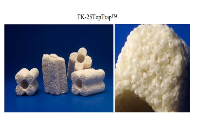
This specialty trap would be loaded right under the high-void, high-density topping layer, such as TK-10 or TK-15. This is because when grading for iron, the objective is to keep the material near the top of the vessel where you have the highest amount of void. If iron migrates through the graded bed and gets to the main bed catalyst, it will hit the pinch point where interstitial void is at its lowest. This would then result in the pressure drop building quickly.
AUSTIN SCHNEIDER (Crystaphase Products, Inc.)
Iron is a ubiquitous foulant across all refining service types and is commonly the primary element involved in compound formation, which causes pressure drop. Delta P issues caused by iron tend to persist even after heating train lines have been pigged and upstream feed filter elements have been put in place. Although iron contamination comes in many forms, including both solids and solutes, when considering pressure drop, iron contamination should primarily be examined as a solid. In this form, it is most commonly encountered as the compound iron sulfide.
Upstream feed filters remove a very large portion of solids moving into the heating train and reactor system. A common action taken to reduce reactor fouling is to implement a filter with a tighter mesh, increasing the particle size range it can capture. This usually results in more frequent filter changes/washes, which operators do not enjoy doing at increasing intervals, with the end result being that the fouling rate is rarely impacted.
Pigging removes any residual iron sulfide crust that may have formed during the previous cycle. While this procedure removes fouling buildup and improves the fluid characteristics and heat transfer capabilities across the heating train, it does not do much to change the fouling rate. In fact, pigging can serve to increase fouling generation initially as removing the corrosion products from the inner piping exposes fresh steel to corrosion pathways.
Although necessary, neither of these proactive maintenance processes serve to keep dissolved iron from passing through the feed filters, nor do they prevent corrosion reactions from occurring on the hot skin surfaces of the heat exchanger or furnace tubes.
Much of the dissolved iron will contribute to catalyst deactivation, and there are catalysts in the industry specifically designed to trap these types of organometallics to protect the main bed catalyst. An example of this is shown in Figure 1, which is a SEM (scanning electron microscopy) image of a precious metal catalyst extrudate that has been poisoned by incoming iron contamination, which is identified in red. This limits the catalyst life but has little effect on the pressure drop.
Solid iron typically takes the form of iron sulfide as it enters the reactor via feed filter bypass, scale/corrosion generation in the heating train (Figure 2), or in-situ particle precipitation followed by agglomeration (Figure 3). Assuming the feed filters are run responsibly and continually, we can focus on the latter two: corrosion and precipitation. This is the material responsible for crust formation in the catalyst bed or ring grading layers, resulting in pressure drop.
Incoming iron of this nature is a direct result of energy input on the way to the reactor driving the reactions for corrosion and precipitation. The only option left for the engineer is to deal with the filtration issue raised by iron sulfide generation and to work with top bed technology suppliers to improve the filtration capabilities of the reactor. The volume for particle storage should be increased to improve the resistance to pressure drop. There are materials available that can greatly expand the reactor’s filtration capacity while minimizing the ∆P. These materials work in a uniquely different manner than standard grading and are able to filter without forming a pressure drop. They are differentiated by their sponge-like structure made up of individualized elements. These types of systems can be designed to handle the equivalent volume of several crust layers.
Additionally, characterizing the foulant is also of high value. It can help identify the source of the foulant and the type of filtration or catalyst system needed to trap the iron. Tools to help with characterization include Total Suspended Solids, Particle Size Analysis, Digital and Electron Microscopy (SEM, which is shown below), and some form of elemental analysis. Engineers should consider using all of these tools to separate iron foulant from catalyst fines and other significant particle sources to resolve problems both inside and outside of the reactor.
PAUL CECCATO (Criterion Catalysts & Technologies)
Iron is introduced to a reactor as either solid particulates from scaling or soluble iron from corrosion, which precipitates as solid iron sulfide in the presence hydrogen sulfide. In both cases, a reactor bed grading system distributes the particulates over a volume of catalyst to prevent surface caking and a rapid pressure drop increase upon restriction of the hydraulic channel. Installing layers of grading materials from high void fraction to lower void fraction above the main catalyst bed creates the desired distribution and filtering effect.
For solid iron particulates, large-shaped materials are utilized at the top of the grading package to prevent accumulation and crusting at the inlet of the reactor. For soluble iron, adjusting the activity of the grading materials from very low at the top of the bed to moderate above the main catalyst slows the generation of hydrogen sulfide to allow precipitation of iron sulfide over the full depth of the grading materials. To assist with control over iron sulfide precipitation, Criterion manufactures OptiTrap[MacroRing] 8.0 mm hollow cylinders. The mild activity and macro sized pores of the OptiTrap[MacroRing] allow for precipitation and retention within the substrate for an overall increase in iron capacity of the grading system.
GATES (Motiva Enterprises LLC)
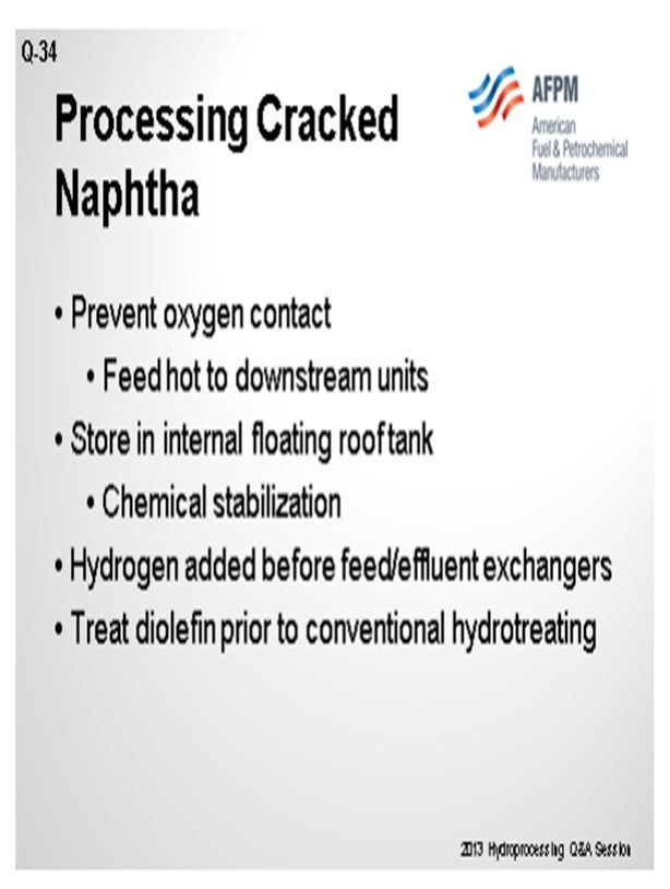
Again, we are trying to prevent the polymerization of the olefin/diolefin. The primary concern is trying to prevent contact with oxygen because that will ultimately lead to gum formation. So the preference would be, if possible, to feed this hot to all the downstream units and avoid intermediate storage. If you will have to put it into tankage, the preference would be to use an internal floating roof tank and add some type of chemical stabilization. So typically, some kind of oxygen scavenger would be put in there. The length of time that material will be staying in tankage may dictate the level of treatment that will be done.
The other concern is that if this material contains diolefin/olefins, as it goes into your feed/effluent exchangers, prior to entering the reactors, it could potentially foul those exchangers. Often, you want to add soak hydrogen or hydrogen upstream of that exchanger. It may need to be considerably upstream to ensure that as the material is going into the exchanger and getting hot, there will be some hydrogen present to prevent that gum formation.
If you are actually going to try and treat cracked naphtha, you will typically want a separate diolefin reactor that will be run at lower temperatures to avoid the polymerization. You will use catalytic hydrogen to eliminate the diolefin and operate it in a regime such that you will not saturate too many of the olefins. You are ultimately trying to put the naphtha into gasoline, so you want to minimize your octane loss for the gasoline pool. As far as the catalyst, look for a catalyst with sufficient surface area and large enough pore volume – going back to Sal’s comment – to manage any silicon or arsenic that might be coming with that cracked naphtha.
WATKINS [Advanced Refining Technologies (ART)]
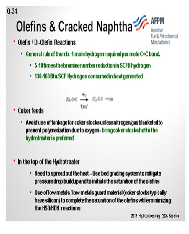
Two of the reasons we are worried about olefins and cracked naphtha in our naphtha hydrotreater are that they are a large consumer of hydrogen and also because the reactions occur quickly. Once the reaction with olefins starts and we have enough temperature, it is hard to stop. We do not want excess temperature to coke up at the top of our hydrotreater. Like David said, with coker feeds, we would like to see them brought in straight from the coker while still hot. They should not be sent to tankage; and if they are, you should blanket the tank somehow and keep it protected from oxygen.
The top of the hydrotreater is where we are worried about excess exotherm. We want to spread out that heat and do the reaction somewhat slowly, if possible. We do not want to have it occur all at once. Generally, we will recommend a graded bed to mitigate that pressure drop and start olefin saturation to avoid worrying about anything else like HDS and HDN or aromatics. In that case, we will be using a low-metals guard material at the top of our hydrotreaters, which also gives us the ability to pick up silicon.
If your system has a high amount of diolefins, again, a dedicated diolefin reactor is important. At a much lower temperature, you can actually control just the diolefin reaction and avoid doing everything all at once by either controlling how much hydrogen goes to the hydrotreater or by keeping the temperature fairly low.
In the top of the main reactor of a coker naphtha unit, again, low metals, a guard material, is recommended. We generally then recommend avoiding the placement of very high-metals, high-active catalysts at the top, if at all possible, so we can try and do the reactions one at the time.
MUKESH PATEL (Reliance Industries Ltd.)
When we have to enable storage of naphtha, if necessary, which is the parameter we should monitor or what type of analysis should be carried out to determine if any gum formation has happened?
GATES (Motiva Enterprises LLC)
Off the top of my head, I do not know the ASTM (American Society for Testing and Materials) methods for that, but there are gums and then there are potential gums a
We run diolefin saturation tests, and I will put the ASTM method in my Answer Book response. We typically shoot for 60 to 80% diolefin saturation.
SHARPE (Flint Hills Resources, LP)
We run diolefin saturation tests, and I will put the ASTM method in my Answer Book response. We typically shoot for 60 to 80% diolefin saturation.
BRIAN WATKINS [Advanced Refining Technologies (ART)]
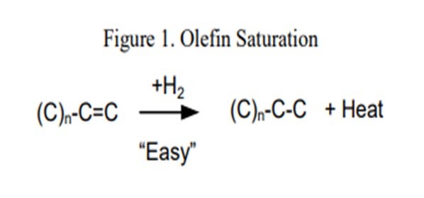
Processing coker naphtha can have several undesirable effects on the performance of the hydrotreater and the catalyst if the system was not properly designed to handle it. In general, coker stocks have a higher level of olefins present from the coking process. Once in the hydrotreater, these olefins will quickly get saturated (Figure 1), resulting in high hydrogen consumption and generation of a lot of heat. As a general rule of thumb, one mole of hydrogen is required per mole of carbon-carbon double bonds, or between five and 10 times the Bromine number reduction in standard cubic feet per barrel (scfb) of hydrogen. This additional heat [130 Btu/scf (British thermal unit per standard cubic foot) to 160 Btu/scf hydrogen consumed], if not managed properly, will initiate additional reactions, quickly creating a very high temperature rise. The high temperatures can accelerate coking and can lead to olefin polymerization, resulting in a dramatic increase in pressure drop. This can set an upper limit on how much coker naphtha can be processed based on the need to limit the heat rise or hydrogen consumption.
A system that is properly size and activity graded is extremely important when processing coker naphtha. ART recommends utilizing a grading system to help mitigate pressure drop buildup. A large inert hold down ring (GSK-19) with a very high void fraction used for trapping large particulates is placed at the top of the catalyst bed. A smaller diameter macroporous ring (GSK-9) that traps iron, as well as other fine particulates, is typically used in the next layer. After that, two types of smaller rings are used as active grading. These materials have a low level of active metals which help begin olefin saturation reactions, as well as provide additional particulate space at the top part of the catalyst bed. Avoiding the use of any highly active catalyst at this point is also recommended. Below the grading system, it is recommended to use a layer of larger size (1/10” or 1/12”) catalyst which provides activity for olefin saturation and additional void space for pressure drop mitigation. This layer is often a catalyst that is suitable for trapping silicon (and arsenic), which is another concern when processing coker naphtha.
An additional recommended practice to help prevent fouling and pressure drop buildup in coker naphtha units is to avoid contact of the coker feedstock with oxygen. It is preferred to bring the feed to the processing unit directly from the coker and avoid use of tankage. If this is not an option, then the alternative is to use a floating roof tank and purge the system to keep a nitrogen-blanket over the feed in order to keep oxygen out. Use of a diolefin treating reactor can also be considered. A diolefin reactor is operated at a much lower temperature in order to selectively catalyze the diolefin saturation reaction and avoid any excess heat generation from sulfur and nitrogen removal.
RAJESH SIVADSAN (UOP LLC, A Honeywell Company)
When processing cracked naphtha, plugging in feed exchangers and heaters may be caused by coking or polymer formation. Polymer formation can be caused by oxygen in the feed with cracked feedstocks. It is preferred to have cracked feeds fed to the hydroprocessing units directly from the upstream unit. Cracked feedstocks that do not come directly from the upstream unit should be stored in nitrogen-blanketed tankage. For units that process straight-run feeds from tankage, as well as cracked feeds, this straight-run feed should also be stored in nitrogen-blanketed tanks as this feed could provide the source of oxygen for polymer formation.
Processing these streams by themselves usually requires a two-reactor system with the first reactor operating at lower temperature to saturate the diolefins and a small portion of the olefins. The second reactor completes the olefin saturation and removes the sulfur and the nitrogen.
DENNIS HAYNES (Nalco Champion Energy Services)
Some issues may arise regarding polymerization. Polymerization in the feed stream may lead to fouling of heat transfer equipment and plugging of the reactor bed. A first step would be to minimize any potential for oxygen contamination as oxygen would act to accelerate fouling reactions. In addition, consideration may be given regarding the implementation of additive chemistries to inhibit polymerization rate (antioxidants) and minimize the potential for foulant (dispersants).
CHRIS CLAESEN (Nalco Champion Energy Services)
There are special low temperature reactor designs utilized to saturate the diolefins before they can thermally polymerize. Chemical programs with antipolymerants and dispersants can also help control polymerization and ∆P (delta P; pressure differential) increase. Reactor bed cleaning programs have been used successfully to reduce reactor ∆P caused by fouling with polymerized olefins and corrosion products.
RAJ PATEL (Haldor Topsøe, Inc.)
Designing a unit for processing coker naphtha can be challenging. The challenge comes from the silica in the feed which can poison the catalyst, high nitrogen in the feed which may be difficult to remove in low pressure units, and high quantity of olefin which can cause large temperature rises in the reactor, as well as very reactive molecules which are the conjugated diolefins. In the presence of small amounts of oxygen, or at elevated temperatures above 450°F, these molecules will radially polymerize to form gum that can foul exchangers or reactors causing poor heat transfer, as well as high rector pressure drop. If the feed contains a significant quantity of coker naphtha, then these diolefins must be removed at low temperatures to prevent gum formation.
The coker naphtha should preferentially be sent directly from the coking unit to the hydrotreater to prevent oxygen contamination. Even straight-run stock, which may be part of the feed component, must be prevented from contacting oxygen by storing the feed in a nitrogen-blanketed storage tank.
Even with strict adherence to avoiding feed contact with oxygen, the diolefins in the coker naphtha can polymerize at elevated temperatures. A dedicated diolefins reactor operating in the range of 300°F to 450°F will ensure that these highly reactive species are removed from the feed before polymerization can take place. Once the diolefins are removed from the feed, then the feed can be heated to the required temperature for silicon and/or sulfur/nitrogen removal. Topsøe has designed a large number of coker naphtha units with dedicated diolefin saturation units to mitigate the polymerization issues.
MIKE ROGERS (Criterion Catalysts & Technologies)
Hydrotreatment of cracked naphtha derived from FCCU, coker, or thermal cracking is a common refinery requirement. In some cases, refineries process these naphthas in a downstream catalytic reformer; while in others, hydrotreatment is necessary to meet gasoline blending sulfur requirements. Treatment of cracked naphtha can pose special challenges due to the presence of diolefins that are produced by the cracking reactions.
Diolefins in cracked naphtha streams from the FCCU and the coker will polymerize when heated, producing gums that foul the pre-heat equipment and main hydrotreater catalyst. To prevent polymerization, these naphtha streams are treated in a diolefin reactor operating at low but sufficient temperature to hydrogenate the diolefins. Typically, the diolefin reactor operates in a down-flow bubble phase with an LHSV of 2 hr-1 to 5 hr-1 and within temperatures between 180°C and 220°C (350°F to 420°F).
The effectiveness of diolefin saturation and protection against polymerization is monitored by measurement of the diene number in the reactor effluent. Typically, method UOP 326-08 (Diene Value by Maleic Anhydride Addition Reaction) is used to generate a MAV (maleic anhydride value) number representing approximately double the diene content in weight percent. Conversion of MAV in the diolefin reactor is in the range of 90 to 95%, and a target MAV number of less than 1 in the product stream from the diolefin reactor typically ensures protection against polymerization.
Catalysts loaded into a diolefin reactor should have a moderate but stable activity to selectively convert diolefins at low temperatures. For units processing coker naphtha containing silicon, a large surface area and high pore volume provide resistance to poisoning. Lastly, for units processing FCCU naphthas, catalysts with a low hydrogenation activity are favorable to minimize olefin saturation and octane loss.
LIOLIOS (DuPont Clean Technologies)
The highly paraffinic nature of the tight crudes and the destabilization of asphaltene molecules can cause precipitation and agglomeration. One of our customers with a gas oil mild hydrocracker switched feedstock to increase amounts of black wax crude. This was a five-reactor system. A guard bed reactor was first, followed by four other reactor beds. In the polishing reactor bed, this customer saw an increase in pressure drop. It was theorized that this pressure drop was caused by asphaltene precipitation and polymerization in the bed.

The following graphs show some of what was happening at this unit. It is a constant feedstock. They raised the temperature to get some additional cracking. You will notice an elevated pressure drop in the last bed shortly after they increased the severity of the unit. If you look at the next chart, you can see where they decreased the severity of operation of the unit and the pressure drop recovered. Our theory is that there was a recombination of those asphaltenes.

SHARPE (Flint Hills Resources, LP)
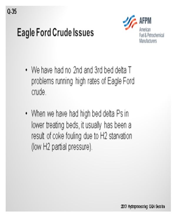
We have had no second and third bed ∆T problems when running high rates of Eagle Ford crude. When there were high bed ∆Ps in the lower treating beds, they were usually a result of coke fouling due to hydrogen starvation, and low hydrogen partial pressure.
GLENN LIOLIOS (DuPont Clean Technologies)
The highly paraffinic nature of tight oil crudes, and the potential increase in asphaltene precipitation when these crudes or cuts of these are mixed with polar asphaltenic oils or cuts, has been well documented. The increase in paraffin content can lead to destabilization of the asphaltene core which can then agglomerate to form larger macromolecules that may precipitate out under hydrotreating conditions.
A number of published documents2 detail the causes and reactions behind this phenomenon and outline methods to determine which crude type and cuts are compatible and what ratios are required to minimize the chance of this phenomenon occurring.
Much of the industry experience indicates that asphaltene precipitation and fouling in process units normally occurs in regions of high heat flux when agglomerated asphaltenes easily crack or dehydrogenate leaving coke-like deposits such as feed/effluent exchangers or where hydrotreater reactions are initiated; i.e., the top bed of a hydrotreating reactor. However, it was observed that a gas oil mild hydrocracking unit experienced a noticeable increase in pressure in a final polishing reactor after the feed to the unit was switched to process a feed that had been mixed with an increased percentage of highly paraffinic (black wax crude) feedstock. At the same time, the severity was increased by lowering the throughput without reducing inlet temperatures. The polishing reactor was the last in a series of five reactor beds, the bed being a separate bed reactor. During the observed increased pressure drop in the polishing reactor, no appreciable pressure drop was observed in the guard bed or main reactor beds. It is important to point out that after the space velocity and feedstock to the system were normalized, the pressure drop decreased almost to the baseline range prior to the event.
It is theorized that the observed bed pressure drop increase in the last bed was a result of asphaltene precipitation and polymerization on the bed that occurred after increased severity reactions cracked the smaller molecules that kept the increased asphaltenes in solution. According to work conducted by Wiehe on asphaltene precipitation3 , asphaltenes are maintained in solution in oil by a micelle type of configuration. This theory has been also explained by other authors4 . The asphaltene core is surrounded by a solvated shell that consists of resins. Resins are molecules with aromatic and naphthenic rings.
Under high severity conditions such as those experienced in this mild hydrocracker operation, the resins can crack into smaller molecules. This can disrupt the micelle type configurations at which asphaltenes are kept in solution, and the asphaltenes can precipitate upon cooling.
Analytical tests carried out on the hydrocarbon feed samples indicated that the asphaltene content (heptane insolubles), although low in comparison with a heavy residue5, was found to be approximately three times higher than the one on the sweet GO FCC feed sample that was being recirculated to the unit and the regular GO sample fed to the GHC.
This theory explains why the upstream reactor beds did not experience a corresponding increase in pressure drop. If it were due to deposits, catalyst fines, or simply rust from upstream units, the first two reactors should have acted as filters preventing the last bed from getting plugged-up.
JUAN ESTRADA (Criterion Catalysts & Technologies)
Two primary mechanisms for pressure drop in bottom beds are coking and asphaltene precipitation. Coking results from operation at elevated temperatures and hydrogen deficiency. Asphaltene precipitation results from a reduction in liquid solvency. The design of VGO hydrotreaters with elevated pressure, low space velocity, and high treat gas rates helps minimize coking; however, elevated saturation of aromatics reduces the solvency of the oil, increasing the potential for asphaltene precipitation in the catalyst bed.
Processing tight oils in the crude diet reduces the aromatic content of the gas oils. For this reason, the coking potential of the feed is lowered, but the potential for asphaltene precipitation increases. With lower feed aromatics and severe hydrotreatment, the solvency change may be sufficient in the lower catalyst beds to precipitate asphaltenes introduced with the other gas oil components from conventional or synthetic-derived crude sources.
The mechanism of asphaltene precipitation from a reduction in liquid solvency has been connected to many historical pressure drop problems involving changes in operation and feedstock qualities such as aromatic and C7/C9 asphaltene contents and the distillation tail. Applying this accepted mechanism to lower bed pressure drop problems in units processing tight oil derived gas oils logically explains recent pressure drop problems in a few VGO hydrotreaters. Refiners continue to learn compatibility limitations of co-processing tight oils in the crude diet, including impacts on VGO reactor pressure drop growth has become a consideration.