Question 36: With higher anticipated charge rates at the coker due to IMO, what are your best practices around defoamer application to minimize impact on hydrotreater catalyst life?
Year
2019
Process
STEVE WILLIAMS (Marathon Petroleum Corporation)
TODD HOCHHEISER (Johnson Matthey)
These trailers are often referred to as pneumatic, dry bulk, or pressure differential (PD) trailers. On-road trailers and railcars have similar functionality although railcars are not usually rated for vacuum, nor do they usually have a filter system. Both types of transport vessels have multiple hoppers. The multiple hoppers are necessary to make sure that the outlet slope is greater than the angle of repose.
A trailer can be offloaded into either an atmospheric pressure hopper or a hopper under vacuum. A vacuum is not required but can increase the offload rate. Once the trailer arrives at the offloading location, the wheels should be chocked, and the trailer grounded. Proper PPE should be worn. The trailer outlet line is then connected to the refinery piping using a flexible hose. All those connections should be locked. It is best to match the diameter of the trailer discharge piping, hose, and refinery piping. If the refinery piping diameter is larger, additional carrier air may need to be added.
There are 3 air uses in a typical trailer: top air for trailer pressurization, carrier air, and aeration air. The air for trailers is usually provided by the truck blower while air used to offload railcars is provided by the refinery. The refinery storage hopper design pressure and relief valve capacity should be checked against blower design. A filter may be needed on the refinery hopper discharge vent. Some factors that contribute to whether a filter is needed are hopper air velocity, hopper catalyst level, and whether a vacuum system is used on the hopper. A filter is recommended upstream of the refinery vacuum system to minimize erosion in the ejector.
Most trailers and railcars have a design pressure of 15-18 psig. Top air is introduced into the trailer between 8 and 12 psig. Carrier air is introduced into the outlet piping upstream of the trailer hoppers. Setting the carrier air flow is part art and part science. Carrier air velocity is recommended to be 10-20 ft/sec. Measurement of carrier air flow is uncommon; therefore, the flow setting is often set based on experience. Some hoppers also include aeration air which can be used to fluff the catalyst. Once the trailer is suspected to be empty, a visual inspection from the top hatches should be performed. Some trailers have handrails on top for increased safety when accessing the hatches. Proper tie-off is required when on top of the trailer. Trailer pressure should be verified as zero prior to opening hatches.
When loading a trailer, the trailer should first be verified as empty and clean by visual inspection. Trailer loading can be accomplished via gravity flow, pressurization of the refinery hopper, or by pulling a vacuum on the trailer. Gravity flow requires a loading facility where the trailer can be located underneath the hopper. The trailer vent for the displaced air is usually routed to atmosphere due to minimal flow. The second option for loading a trailer is to pressurize the catalyst hopper and add carrier air at the outlet of the hopper. In this scenario, the trailer relief valve capacity needs to be evaluated. Additionally, a filter system is necessary on the trailer vent. This can be a filter system included with the trailer or the vent can be connected to a filter system at the refinery. Another option for trailer loading is to utilize a vacuum system. This option is not readily available for railcars. The vacuum source for the trailer is typically the truck blower pulling suction from the trailer through a filter. For vacuum filling, there are usually multiple fill lines as it is difficult to fill more than two compartments from a single inlet. Most trailers have weight gauges to help prevent overfilling and help determine when to switch hoppers.
LUIS BOUGRAT (W. R. Grace & Co.)
FCC catalyst handling activities constitute an important piece of day-to-day unit operation that can have a tangible impact on operational safety and performance. The health of the circulating catalyst inventory is highly dependent on the success of the routine fresh catalyst transfer process from the delivery vessel to the fresh catalyst hopper – or equivalent recipient.
General Catalyst Transfer Guidelines
From a safety perspective, the key is to identify and actively monitor the mechanical design limits of the lines, fittings and equipment involved throughout each step of the catalyst handling activities. It also becomes critical to properly ground all loading/unloading vessels, equipment and piping/hoses to avoid static electricity hazards. Regardless of the procedural complexity of the material loading/unloading process, a good practice is to at least verify the following items prior to any loading or unloading activities:
1. The shipping truck, or alternative delivery medium, has been properly secured from movement by at least two independent means.
2. Correct lineups of the hose, hopper and corresponding piping. If applicable, any hose connections should be properly secured at each end.
3. Correct valve positions to ensure safe and adequate catalyst routing and flow control. Ensure that the correct material is lined up to the correct storage hopper or recipient.
4. Visual inspection of all equipment and fittings associated with the procedures to ensure that they are in proper working condition.
5. Confirm hopper inventory prior to loading the hopper to prevent overfilling and potential loss of containment.
6. Operators should observe the entire loading process, never leaving the loading process unattended.
All personnel involved in the catalyst handling activities should also adhere to the PPE requirements associated with the local policies and regulations at all times. Permissible exposure levels of the various components in the catalyst are present in the product safety data sheets and should be reviewed with monitoring performed when needed.
Considerations for Catalyst Loading to a Fresh Hopper
Fresh catalyst is typically delivered in railcars or trucks when shipped within North America. The specialized trucks can typically deliver 20 to 25 tons based on multiple factors and regulations, and railcars can carry roughly 80 to 90 tons. The maximum allowable loading limit for individual trucks should always be observed while leaving any necessary clearance within the load compartment for pressurization and depressurization requirements. Apart from potential impacts to transportation safety, overloading of the truck or railcar can also lead to undesired catalyst handling losses that are often costly and may result in employee, public and environmental exposures. All catalyst loading and unloading activities are usually carried out through pressure differentials or gravity feeding. Silo or tank trucks are typically pressurized while the fresh catalyst hopper is placed under a vacuum, using steam ejectors, to establish an adequate driving force for catalyst flow. Prior to pulling a vacuum within a truck, storage hopper, or any other vessel, it is critical to ensure that the corresponding system is rated for the targeted vacuum conditions. Establishing an excessive vacuum within a vessel or delivery medium not rated for this type of service can lead to personal injury, irreversible mechanical damage that can also compromise the catalyst containment efficacy of the system. Railcars are not typically rated for vacuum service. As such, a corresponding lid should be opened, or at least partially cracked, during catalyst transfer activities to prevent the buildup of negative pressure.
Catalyst loading and unloading activities are highly dependent on the mechanical integrity of the piping and fittings connecting the trucks and storage hoppers. Fouled piping or fittings can significantly deter catalyst transfer efficiency while potentially posing a back-pressure hazard to upstream equipment. Therefore, adequate debris screens should be installed and frequently inspected at the bottom of storage hoppers to help prevent plugging hazards. Catalyst manufacturers have quality assurance controls at the manufacturing plants to prevent debris ingress into the delivery medium. The catalyst should be kept dry and free of contamination throughout the catalyst handling activities to ensure proper flow characteristics. Any carrier air or fluffing air supplies should be regulated and maintained adequately dry at all times, particularly in winter service. Steam ejectors for vacuum service can also introduce moisture into the system and lead to catalyst agglomeration issues.
The carrier air rates should be controlled such that the superficial velocity through the catalyst transfer lines is maintained at 10 to 20 ft/s at all times. Excessive line velocities can lead to accelerated wear of the piping and internals based on the high loading and unloading frequency for typical FCC units. Long-radius elbows and cushioned tees help mitigate erosion across any change in piping direction but can still be susceptible to mechanical wear throughout long-term operation. Ceramic, cast basalt, and/or alumina linings can be used for susceptible piping sections to improve mechanical resiliency throughout catalyst transfer cycles.
Considerations for Catalyst Unloading from a Spent Hopper
With respect to catalyst withdrawal from the regenerator and spent catalyst hopper, the same considerations and best practices apply. However, there is also an increased focus on catalyst temperature throughout the catalyst transfer activities. The mechanical design limits for the transfer piping, spent catalyst hopper and truck or railcar containers should be observed at all times. Adequate insulation or PPE requirements should be established to properly protect field personnel from the high temperatures associated with this type of activity. Entrained flue gas from the regenerator should also be accounted for throughout safety assessments and procedure development. Catalyst temperatures can usually be controlled by controlling the rate of spent catalyst withdrawal from the regenerator and storage hopper residence time. The superficial velocity limits for the catalyst transfer lines should still be observed and the higher temperatures should be taken into account.
Considerations for Emissions Control
Engineering controls are the preferred means to control personnel exposure. The use of closed systems for storage, dustless systems for material transfer, ventilation for industrial hygiene and dust collection are all highly recommended. Good housekeeping practices should be employed to reduce airborne material and the accumulation of settled dust. Vacuum systems should be equipped with High Efficiency Particulate Air (HEPA) filters. Dry sweeping is to be avoided as it can result in re-distribution of material. Airborne dust levels must not exceed the permissible exposure limits (PELs) that are found in section 8 of the product MSDS. Be aware that it is very difficult to visually determine airborne concentration of dust.
The actual level within the hopper or storage vessel should be frequently monitored via manual gauging or reliable instrumentation for particulate service. Overfilling of the storage hopper represents a common root cause of excessive catalyst handling losses and emissions throughout catalyst loading and unloading activities
Frank Tracy (ConocoPhillips)
The primary areas of concern include:
•Coker feed circuit above 450 °F
•Bottom section of the fractionator, including internals
•Heater charge pumps and associated piping
•Heater tubes
After entering the Coke Drum, conventional wisdom is that the naphthenic acids have been held over 750 °F for a sufficient time that they no longer exhibit the naphthenic acid type corrosion behavior.
Considerations in determining the acceptable level of TAN include:
•The type of acid in the stream
•The amount of reactive sulfur in the stream.
•The presence/absence of continuous coke layer on the metal surface
•Velocities & turbulence can accelerate corrosion rates
•Short periods of high TAN levels in a stream can cause serious damage.
Acceptable TAN levels are calculated by our metallurgical experts based on the above considerations. When unable to manage acid levels to the acceptable levels by crude selection we must address the problem with metallurgy upgrades. Our approach is to use 317L SS for most components with Alloy 625 used for weld overlay or for tower internals.
We have quite a bit of experience with Naphthenic Acid Corrosion in the crude vacuum unit, but not a lot of experience with NAC in the coker. However, we have one unit that upgraded the metallurgy of the piping between the coker fractionator and the heater due to NAC.
Eric Thraen (Flint Hills Resources) The Coker VTB feed piping and heater charge piping are most susceptible to naphthenic acid corrosion. The metallurgy and TAN limits on these sections are similar to those in the upstream Vacuum Unit VTB section. The furnace coil needs to be evaluated also. Naphthenic acids are destroyed at the temperatures present in the coke drum. The Coker furnace coil metallurgy needs to be evaluated based on process temperatures in that section of the heater. 9 Cr tubes have been the standard but as TAN increases certain sections of the heater may need to be upgraded similar to what is done in the upstream Vacuum units, depending on the Inspection findings. The interaction between TAN and line velocity must also be understood as piping erosion greatly accelerates naphthenic acid corrosion.
Sam Lordo (Nalco Company) The delayed coker circuit most susceptible to naphthenic acid attack is the feed circuit, downstream of the furnace is a low risk are as the furnace conditions thermally degrade naphthenic acids. Even though typical guidelines are used with respect to the velocity (shear stress), temperature, metallurgy and TAN levels to identify the potential risk. The incident of identified naphthenic acid attack is minimal. In most cases the size of naphthenic acid molecule in coker feed is too sterically hindered to be very aggressive.
Frank Tracy (ConocoPhillips)
Monitoring drum wall conditions during the drum cycle is best performed using strain gauges. Each strain gauge location will typically be fitted with gauges in both the axial and hoop directions and have an associated skin thermocouple. These can be seen in the photograph.
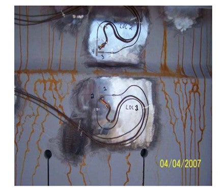
The largest stresses typically occur during the water quench portion of the drum cycle. Strain gauges allow a refiner to minimize stresses during this critical portion of the drum cycle by adjusting quench water rates. However, this is a longer-term project as you must evaluate enough cycles to have representative data for evaluation before making an operating change and then collect enough data afterwards to make a meaningful comparison.
Selecting the locations for strain gauge installation is something that requires some careful consideration. Strain gauges can be retrofit onto existing drums and are recommended as part of new coke drum installations. Typically, it is only necessary to fit strain gauges on one drum in each set of identical drums receiving the same feed since all drums will behave similarly.
Skin temperatures alone do not provide the same information as strain gauges. They can be used to help ensuring adequate back warm. They may be useful, if strategically deployed, to possibly identify uneven quenches.
We have used or are currently using strain gauges at several of our cokers and plan to use them at some additional locations.
Eric Thraen (Flint Hills Resources)
We have conducted several coke drum stress studies using outside consultants. Coke drum skin temperatures and strain gauges are included in the stress studies. The strain gauges are used primarily for these engineering studies, while the temperature indicators are used by the operating personnel, along with quench water flowrates and coke drum pressure rate of change during the drum cooling step to manage the rate of cooling so as to meet the targeted coke drum lifecycle. Quench water flow and coke drum pressure are included in the coke drum cooling program as added checks to ensure against too rapid quenching during the cooling cycle. The minimum coke drum preheat prior to switching feed into a drum is based on strain studies by the outside consultants. Although the stresses during water-cooling are generally highest, a minimum drum preheat is also established to prevent excessive stresses during the drum heating cycle.
Eberhard Lucke (Commonwealth E&C)
Drum skin temperatures are mainly monitored in the critical areas around the drum skirt attachments and the first 1-2 circumferential welds from the bottom in the cylindrical portion of the drum. The data from these skin temperature elements can be used in the DCS to monitor the change in temperature over time during the critical stages of the drum cycle, the drum quench and the drum warm-up/switch. Keeping the dT/dt in a certain range will minimize the thermal stress on welds and drum wall and will increase the lifetime of the coke drums. These dt/dt values can be integrated into the control scheme for the quench water ramp function, the warm-up controls and the drum switch control, depending on the degree of automation you have in your unit.
Frank Tracy (ConocoPhillips)
There is not a one-size-fits-all answer to this question. However, we believe that an arrangement that closely matches the conventional bottom center upflow arrangement will provide more uniform thermal stresses on the drum and minimize operational impact.
Within ConocoPhillips we have multiple cokers that have retrofitted valve-type unheading devices onto bottom heads and use single side feed entry. These drums have not had any significant operational or mechanical issues resulting from the retrofits to date. We also have one coker, which still has manual bottom unheading, that has had dual side entry for more than fifty years. We have one new coker that is in construction that will utilize dual side feed entry.
One ConocoPhillips Coking Technology Licensee installed valve-type unheading with single-side entry. Upon converting to single side entry, they experienced significant temperature gradients in the drum resulting in drum deflection and a permanent “banana” shape as well as an increase in blow outs. They are converting to dual side entry and early reports are that this has improved their operation back to where they were with original bottom center upflow arrangement.
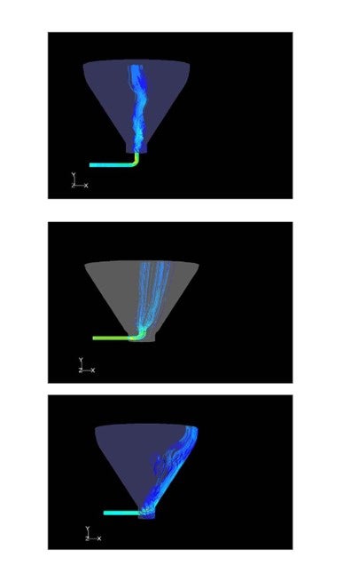
Because there are so many factors to consider; including feed properties, operating conditions, and drum geometry; we are using CFD modeling to aid in assessing the number, location, and entry angle for feed nozzle(s). CFD modeling in this application is still a work in progress for us, but we believe it is a useful tool. In some cases,
the additional complexity and cost of dual-side feed entry is warranted while in others it is not.
The next three CFD model snapshots illustrate: 1) bottom dead center feed, 2) single side entry for a case where single side entry might be selected, and 3) a case where single side entry as configured might not be recommended. These are different drums with different feeds, conditions, and geometries. ConocoPhillips have CFD modeled several variations around single vs. dual side entry, location of feed, and entry angle.
For dual-side entry there must also be a reliable piping system that is designed to support the nozzle configuration.
ConocoPhillips have licensed four retrofits to dual feed nozzle systems and can provide Licensing assistance in this area.
Finally, DeltaValve have a prototype for a retractable feed device that attempts to simulate bottom dead center feed entry. This is reported to be going into trial sometime in the fall of 2010.
Jim Johnson (Marathon Petroleum)
It is our understanding that industry is leaning toward dual feed nozzles at a 45-degree angle to the bottom cone when installing slide valves. Marathon’s refineries have nine drums with single side entry and have no issues. We did not see our hot drum occurrence increase when we converted from a bottom entry to a side entry when installing the slide valves.
Eberhard Lucke (Commonwealth E&C)
I have seen no major problems with the single inlet nozzle on the side of the drum cone, if designed properly. I also haven’t seen any significant advantage in using multiple feed points around the cone. The single feed injection point should be angled slightly upwards. I like the concept of going back to the old “bottom inlet” flow pattern with the new slide valve designs. I would have to see that one in operation though before I would recommend it.
Ralph Goodrich (KBC Advanced Technologies, Inc.)
Cokers today are normally designed to operate to maximize liquid yield from the unit. This will require the coker to operate at as low a recycle as possible while still maintaining the required product specifications for the heavy coker gas oil (carbon content, metals, asphaltenes, etc.). For a low recycle operation a spray chamber is the best-in-class.
Although it has been shown in the past to work in some units, there are some reliability issues as the grid requires frequent cleaning/replacement. In addition, any packing such as grid in the wash zone will require sufficient wash oil to maintain a minimal wetting rate to avoid coking in that section. This additional wash will increase the recycle thereby losing liquid yield. Thus, what we typically see today from the licensors are spray chamber designs which provide both higher reliability and lower recycle rates.
The lack of grid or other contact surface does tend to increase the Heavy Coker Gas Oil (HKGO) backend distillation and contaminants, but the improved reliability overrides the quality falloff.
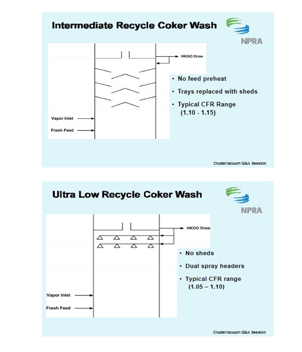
Dual spray headers should be provided to further improve reliability and each should be sized for 50 to 75% of the total required wash rate. Wide angle full or hollow cone sprays (7 to 20 psi, 120° spray angles) should be specified with the hollow cone sprays providing the lowest recycle option. The smaller free passage area compared with a full cone spray, however, may make the nozzle more susceptible to coking.
The spray pattern requires sufficient overlap between the sprays but not as much as that required with a grid design. This allows the design to include fewer nozzles, larger free passage areas, and larger droplets resulting in a lower tendency for nozzle plugging and entrainment.
We have also seen some more novel designs recently which add more equipment in this section of the tower to both help clean the gas oil product and minimize the recycle.
The following slides illustrate the general progression of coker wash zone design modifications corresponding to the increased incentives to reduce recycle.

Frank Tracy (ConocoPhillips)
ConocoPhillips-designed cokers utilize an open chamber wash zone. Wash oil is delivered through dual spray headers equipped with hollow cone nozzles that provide redundant spray coverage. We do not have any experience using grid in this service.
Eberhard Lucke (Commonwealth E&C)
The answer to this question depends to a certain degree on the type of coker operation and the respective operational parameters. For an anode grade operation with a decent wash oil rate and higher recycle ratios, my experience with structured grid in the wash zone was excellent. We just had to make sure the liquid flow to the grid was always above the minimum required for wetting the surface area. In fuel grade operations with very low recycle ratios and minimized wash oil flow rates, I preferred the open spray chamber design.
Doug Meyne (Champion)
Corrosion inhibitors (filmers) have been known to cause deposition in several different ways. Generally, the cause is injection into an overhead that is too hot, flashing off the carrier, or injection of neat chemical, flashing off its solvent. Even if the solvent doesn't flash off completely, filming inhibitors lose solubility at higher overhead temperatures (>280F) and the carrier stream concentration can get high enough to precipitate the filmer active ingredients. Once that precipitation occurs, there are several scenarios listed below that can unfold.
1)Corrosion inhibitors can lose their solvent and begin to slowly dehydrogenate in the presence of the flowing hot vapor, particularly without a slipstream. Depending on the process environment (T, P, V), a dehydrogenated filmer can accumulate in a localized region and become a coke-like material that can become a foulant.
2)Elemental sulfur can be formed in the process oil from unrelated events. If an unsaturated bond is created in the filmer by dehydrogenation, there becomes an opportunity for cross-linking with sulfur, forming a rubberized foulant coating the inside of the pipe. This rubbery compound is not uncommon in overheads, and, in at least one instance, it has been seen to have become thick enough to increase pressure drop in the overhead line.
3) A crude unit filming inhibitor is usually an amine. Fixed in place due to deposition by solvent loss, it can react with the HCl in the vapor, forming an amine salt. Being a weak amine, this does not happen quickly as compared to the neutralizing amines in the system. Under normal operations, the small amount of filmer salt of HCl that forms remain mobile in a liquid form and is removed from the system with the rest of the filmer. But once immobilized as a precipitate, it can be, and has been shown to be, corrosive enough to corrode injection quills and even cause through-wall piping failures.
Neutralizers
The route to fouling caused by neutralizers is substantially different than that of corrosion inhibitors. We should ignore those cases caused by some refineries that attempt to use alkaline metal hydroxides, like NaOH, as their overhead neutralizer. Those cases do exist but are rare for obvious reasons.
Neutralizers themselves will not foul. They must be in a salted form to foul; however, even the salted amines rarely foul. Exceptions to this general rule are those that fall into the –diamine category such as ethylene diamine or some of the steam neutralizers currently in use. These form high melt-point, oil-insoluble salts that will accumulate on trays and draw pans and years ago were responsible for a rash of unplanned shutdowns of atmospheric distillation columns. In rare occasions, such as injection into vacuum columns, some of the solid salt formers such as morpholine have caused pluggage in towers, again forcing shutdowns. The larger fouling problem from neutralizers comes from the corrosivity of their chloride salts to most metals. This topic has been discussed extensively over recent years. Below is a brief summary.
•Amine and HCl salts can precipitate from the vapor upstream of the water dew point.
•They precipitate onto cooler surfaces, wherein their hygroscopic nature makes the deposit wet and corrosive. As more salt accumulates, the environment becomes extremely corrosive.
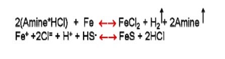
•The process is the following: the salt forms, ionizes in small amounts of water forming H+ and Cl- that corrodes iron to FeCl2 releasing H2 and the amine. The FeCl2 then easily converts to a FeS precipitate, thereby releasing the HCl to cause more corrosion. •The pipe/tube gets thinner, and the deposit gets thicker, with the outer layer comprised of mostly FeS, and the lowest layer, against the metal, rich in FeCl2.
•Deposits can continue to grow until they plug off an exchanger. The deposits will almost always be reported as FexSy or its oxide. •What happens to the amine? With every mol of Cl reacted with FeCl2, a mol of amine is liberated to evaporate away.
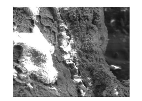
The image below was taken of a corrosion probe in service where salting was prevalent, with the SEM settings set such that HCl fluoresces. The outer layer of the probe deposit has been partially fractured away. On the left side of the image, where the outer layer is missing, the chloride concentration is obvious. In an edge view of the fracture, just right of center, note the presence of chloride largely under the FeS layer, with some small amount seemingly embedded in the FeS at other locations.
Eric Thraen (Flint Hills Resources)
We have experienced crude tower fouling due to neutralizer salt deposition on two occasions. Both involved the direct injection of neutralizer into a crude tower return stream – top reflux or top pumparound. Neutralizer injection to control overhead corrosion in crude overhead condensing systems is less likely to cause this fouling in the crude tower but care must be taken to control the injection rate within limits so that excess neutralizer is not present in the top reflux stream. Good desalting and well-managed caustic injection limit the chlorides in the crude tower overhead which limits the neutralizer requirement in the overhead system.
Jim Johnson (Marathon Petroleum)
We have experienced pitting from under-salt corrosion in the crude unit overhead exchange in four of our refineries. The analyses of these deposits indicate that the pitting was from chloride salts associated with various amines, including those found in our corrosion treatment programs. The pitting and residual iron foulant has been concentrated in the top/outlet section of the bundle. Three of the systems utilize water wash while the fourth does not, with the foulant pattern being similar regardless. The chloride salts formed by either process amines or from the chemical program are not captured with the water and deposit toward the back of the exchanger above the process outlet. In these exchangers the bottom section has not shown any appreciable corrosion.
Paul Fearnside (Nalco Company)
The vast majority of crude tower OVHD deposition is maybe related to the neutralizer salt deposition temperature. This in turn is determined via the partial pressures of the salt in question. Controlling not only the amount of neutralizer injected, but also the number of chlorides and SOx acids is key to eliminating this. Good, consistent, desalter performance is a must. Caustic injection into the desalted crude must be maintained and monitored at all times to minimize the chlorides. If crude OVHD waters are used as a source of desalter wash water, then determining the number of neutralizers in this water is necessary to understanding the salting potential within the upper tower internal sections, from recycled neutralizers. Oxygen sources into the desalter wash water must be eliminated to minimize the amount of SOx acids present. Use of an ionics simulation model, such as NALCO’s Pathfinder®, routinely is necessary to understanding and maintaining established corrosion and fouling KPI’s.
Sam Lordo (Nalco Company)
The vast majority of crude tower OVHD corrosion caused by chemical additive program can be attributed primarily to the neutralizing agent (organic amine or ammonia) and their salts. Filming amine corrosion inhibitors are not known to be corrosive if applied properly. Neutralizer selection should be done taking in account overhead circuit configuration, metallurgy, operating parameters. Corrosion incidences from neutralizers are generally related to:
•Deposition of the neutralizer salt in the ovhd equipment upstream of the water formation
•Misapplication of the neutralizer, such as, injection without a dispersion medium
To minimize neutralizer salt corrosion the follow steps can be taken:
•Selection of the proper neutralizer is done using simulation programs such as Nalco’s PATHFINDER® program. This lets one select the neutralizer that provides the necessary protection without formation of harmful salts in areas of the circuit that is not adequately waterwashed.
•Use a good simulation program routinely (up to everyday) to minimizing overdosing the neutralizer.
•Minimize the number of acids, such as chlorides, organic acids, etc., by improving desalting and using caustic.