Question 67: The industry continues to experience process safety incidents associated with FCC electrostatic precipitators. What are you doing to prevent these incidents?
REYNOLDS (Phillips 66)
Phillips 66 has six ESPs (electrostatic precipitators) in service. We have not been immune to serious incidents on our ESPs. In 1994, we had an ESP explosion, which led to a fatality. So, in order to minimize the likelihood of these kinds of incidents happening again, the company has a standard that all of the refineries are required to follow. It lays out how your safety system is supposed to be configured and which features it is supposed to have. The compliance of the standard is tracked at the corporate level, so all of the refiners have to report if they continue to meet the standard. We have one wet ESP that is downstream of the scrubber, and it must meet the compliance just like regular ESPs.
One of the features required by this standard is that the ESP shall shut down if the main FCC safety system engages or trips, regardless of the cause. There are several other features. If the inlet CO (carbon monoxide) level exceeds the prescribed limit in the standard, which says that it can be no greater than 5,000 ppm (parts per million) of CO, the safety system engages. Also, if the air preheater has a safety system on it which then trips, the ESP is required to trip along with it. The ESP must have its own separate shutdown button. The CO is used basically as a surrogate for other combustible material. CO is combustible itself; but if you are having poor combustion in your regenerator, you are likely to be generating CO as well. One of the more important features is that the ESP cannot have the capability to re-energize itself after it trips.
So the highest potential for operating on ESP and explosive composition in your flue gases during startups comes from the use of torch oil along with air preheaters, which can lead to poor combustion. Our recommended practice is to keep the ESP down during startup until the unit is stable. Stability is defined as feed in the unit, stable pressure balance, CO within limit, and nothing bypassed in the safety system. For certain locations, you may not be able to have the luxury of starting up without ESPs. So if you do that, the standard recommends that you have an air preheater safety system as well.
The standard includes some recommendations; for instance, minimizing the personnel around the ESP when you start up or shut down or if there is an upset. It also recommends utilizing the methane analyzer in conjunction with the CO analyzer. And for the sites that do start up with ESP online, having a methane analyzer – in addition to a CO analyzer – is strongly recommended. The standard includes some scenarios you must consider whenever you do a PHA (Process Hazard Analysis), such as the loss of combustion air or any kind of upset in the regenerator, upset in the stripper, low-riser outlet temperature, and pressure reversals. A lot of the information I used for today’s responses came from a presentation by Phillips 66’s own Mike Wardinsky at the 2009 AFPM Q&A Principles & Practices.
LARSEN [Marathon Petroleum Corporation (MPC)]
In Marathon, we have two units with ESPs on them. Our setup is very similar to what Mark described with Phillips. Any activation of the normal FCC SIS (Safety Instrumented System) will de-energize the ESP. On the slide, you can see some of the limits that we use. Our trip point for CO is 1500 ppm, which is a little more conservative. Also, we will trip the ESP if excess oxygen is less than 0.1%. So, either of those inputs will act to de-energize the ESP. For safety purposes, we only run our ESPs energized during stable normal operations, not during the times of hot standby or startup, etc.
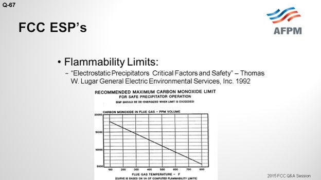
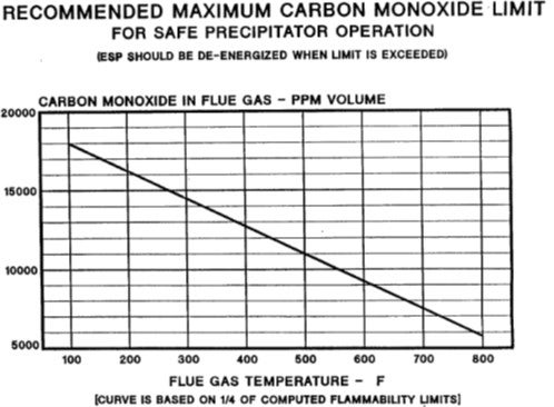
A lot of thought can go into the selection of the right number to use for de-energizing the ESP. An example is the chart on the next slide which includes some numbers, based on the molecules and some inflammability assumptions. This is an example, published by Thomas Lugar at GE1 in 1992, which shows you the magnitude and framework of the danger zone for CO in relation to ESP operation. So, with that, I will put in a plug for our Principles & Practices session tomorrow. I believe it has a topic on ESP safety as well, which will be discussed in more detail tomorrow morning.
KEVIN PROOPS (Koch Industries, Inc.)
Mark and Nik, thank you for your comments. I had the misfortune of visiting the unit Mark mentioned about the week after that catastrophe happened. I want to add a couple of comments to what you described during the startup (when that explosion occurred). Natural gas backed in from the fractionator, through the reactor, and got all the way to the regenerator. I believe that there would not have been any significant CO at that time. Oxygen was high.
So panel members and the audience, if you are worried about ESPs on startup, recognize that they can be very abnormal to what you are used to seeing. I believe the incident investigation also found that the ESP had been in a de-energized state, but it still exploded. So, you have to watch out for potentially explosive mixtures of oxygen and methane at higher temperatures.
ROGER LANOUETTE (Monroe Energy, LLC)
I am curious about the shutdown system. Our analyzer people are telling us that there is interference with CO and methane in doing the analysis and calibration difficulties. Is there a specific analyzer that you have come across that is better for this kind of service? The second part of this question is: Is this an SIL (Safety Integrated level)-rated shutdown system?
UNIDENTIFIED SPEAKER
As far as the analyzer, I cannot speak to what works better in others. I do not think we have a standardized analyzer as far as I know. Do we?
LARSEN [Marathon Petroleum Company (MPC)]
My answers will be published in the final Answer Book. In them, I have detailed the specific analyzer we use. I know a lot of folks are going to the TDL (tunable diode laser) technology, which is a question later on. I think we will talk about response time in Question 76 in a little while, too. I can meet with you after the session to go over the specific analyzer we use with good success.
EMERSON FRY (Delek Refining, Ltd.)
Does anyone have any experience or insight as to whether or not this would be important to have in a partial-burn unit with a CO boiler on the backend? Is that at any greater or lesser risk than a full-burn unit?
J.W. BILL WILSON (BP Products North America Inc.)
Just to add another question about it, is there greater risk with an ESP and CO boiler or is the risk the same? It is at least the same. Okay. We actually managed to blow up an ESP that had a CO boiler on it, so the risk is there. So yes, I certainly think the standards will be the same on our units. I imagine other people who have standards will probably apply the same standards.
RIK MILLER (Phillips 66)
I will address two issues. One is the analyzer. As Nik said, the Phillips 66’s standard also calls for TDL analyzers because they are very fast-responding and very accurate and sensitive for CO. You can also get a TDL for methane. Some of our units have that as well.
As Kevin pointed out, the incident that Mark mentioned would not have been stopped by one of these analyzers. The explosive mixture was fuel gas, and the ESP was not energized at the time. What that site and about half of our other FCCs have done since then is install these overhead blinding devices between the reactor overhead and the main fractionator. Those are reusable devices that can seal off the reactor from the main fractionator so you avoid getting migration of fuel gas or other hydrocarbons during periods when you are down or starting up. Those are very effective, and we recommend them strongly in our system.
ROBERT (BOB) LUDOLPH [Shell Global Solutions (US), Inc.]
I would like to expand Question 67 to include the representatives of the electrostatic precipitator manufacturers who may be in the audience. What are the electrostatic precipitator manufacturers doing to help improve the safety and operation of their equipment, and, in turn, the overall safety of the refining facilities?
NEIL DAHLBERG (Hamon Research-Cottrell, Inc.)
Hamon Research Cottrell has supplied a large number of precipitators to refineries in the United States over the past 15 years. Many of these suggestions are implemented in our design, and we participate in a HAZOP (Hazard and Operability) study at the beginning of each design process. An additional level of protection would be to limit the power to the operating transformer rectifies at startup to stay below the threshold of sparking, which will eliminate a source of sparking in the precipitator and a potential source of ignition of combustible gases.
NIKOLAS LARSEN [Marathon Petroleum Company (MPC)]
The function of an ESP is to remove particles from gaseous streams by passing the gas between a pair of electrodes: a discharge electrode at high potential and an electrically grounded collecting electrode. Sparking in an ESP is an ignition source for a fire or explosion if enough combustibles and oxygen are available.
Specific to FCC units, the biggest concern is carbon monoxide (CO). CO is very unstable; and as such, it is difficult to measure and deliver the information fast enough in order for a manual process adjustment.
Marathon Petroleum Company (MPC) utilizes an extractive system in one FCC unit, and the analyzer is the ABB AO2000 platform with a Magnos 106/206 Paramagnetic Oxygen Analyzer and Uras 14/26 Non-Dispersive Infrared CO Analyzer. Our analyzer is mounted on the deck at the duct; so our sample line is very short, probably in the 10- to 20-foot range. Overall, we have been pleased with this setup.
Others in industry have had success with tunable diode laser analyzers (see Question 76). MPC automatically de-energizes an ESP at a conservative level of either excess O2 (<0.1%) or CO (>1500 ppm). Other actions that de-energize the ESP include activation of the SIS Feed Divert Sequence, control room ESD (emergency shutdown) button, and two field ESD buttons. There is no automatic re-energizing. MPC also does not energize an ESP during times of unstable FCC operation, such as startup or hot standby, when torch oil is being utilized.
The following additional resources are available for your review.
-
“Reducing the Risk of Fires and Explosions in FCC Electrostatic Precipitators”, Michael Wardinsky’s presentation at the 2009 AFPM Q&A Principles & Practices.
-
“Advances in Fluid Catalytic Cracking – Testing, Characterization, and Environmental Regulations”, edited by Mario L. Occelli; Chapter 18 (18.4.8) on ESP Safety by Jeffrey Sexton.
-
“Electrostatic Precipitators Critical Factors and Safety,” a paper by T. Lugar which also calculates safe limits for CO when operating an ESP (GE Environmental Systems, 1992).
ALAN STAHL (CSI Engineering)
CSI Engineering evaluates the safety procedures and systems of our client refineries’ electrostatic precipitators (ESPs). Of particular importance is the precipitator emergency shutdown system that eliminates high voltage sparking as a source of ignition in the event of hazardous process conditions. Shutdown system designs vary in details of wiring, control inputs, and procedures for use. Some systems and practices prove to be inadequate. We apply our experience to advise our clients of what we consider the most effective features and procedures.
CHRIS STEVES (Norton Engineering)
Some of our clients have installed automatic shutdown systems for ESPs, which may be triggered by any of the following initiating factors:
-
High ESP inlet CO or methane concentration [as measured by tunable diode laser (TDL)],
-
FCC unit trip, or
-
CO boiler trip.
Some refiners will also keep the ESP de-energized during unstable phases of the startup, such as when first introducing torch oil to the regenerator. A thorough analysis of the unit configuration and potential causes of an ESP incident should be reviewed by a multifunctional team in the refinery so that the best solution can be implemented. Consultation with outside experts familiar with FCCU ESPs and previous industry incidents is normally useful.
Year
2015
Process
Question 31: What is the threshold concentration of arsenic and phosphorus requiring a dedicated trap system? How are the arsenic and phosphorus trap systems specified,and what are the controlling mechanisms?
WATKINS [Advanced Refining Technologies (ART)]
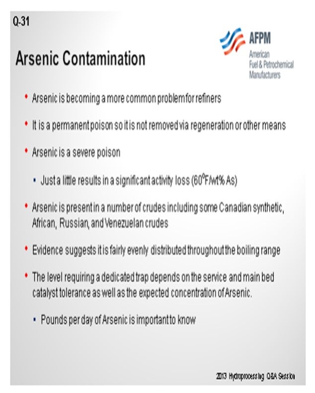
Arsenic is a big concern because it is a permanent poison that causes fairly significant activity. We generally see around a 60° Floss per weight percent pickup; so you will want to pay attention to it. As a side note, it is also common in most fractions of hydrotreating: so anything from naphtha to heavy gas oil. Since there are a large number of process variables, catalysts, and operating conditions, the level that would define where a dedicated trap is actually needed will really depend on how much arsenic is coming into your reactor and possibly what other catalyst is present there as well. Generally, we like to monitor how many pounds of arsenic per day are coming into your hydrotreater; then, we look at the controlling mechanisms for deactivation.
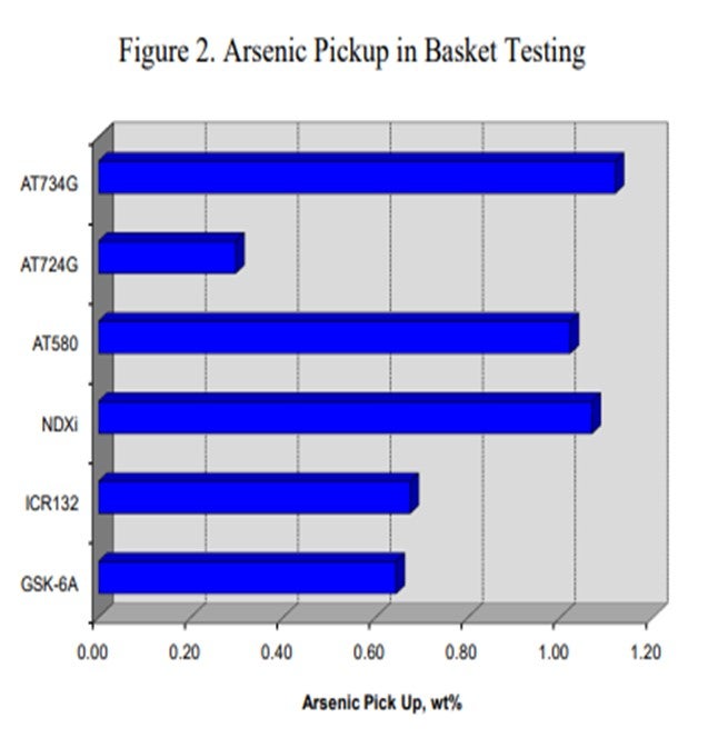
The chart on the left side of the slide compares relative arsenic pickup on the catalyst to the actual amount of nickel present in the reactor. One of the major factors for how much arsenic your reactor can hold is how much nickel is sitting at the top of your reactor, or even in the whole reactor. So, as you go from left to right, you can see you can pick up quite a bit more arsenic.
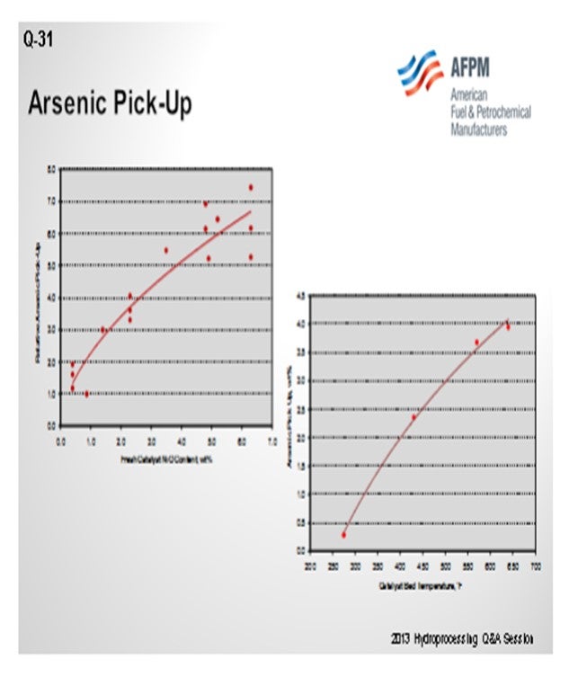
What also controls arsenic pickup is the operating temperature of your hydrotreater. You can generally look at the weighted average bed temperature or the actual temperature of where the catalyst is located. Something like a diolefin reactor down at 250°F to 300°F will pick up a very low level of arsenic. Whereas if you get up into the 650°F to 700°F range, that same catalyst can pick up a significant amount if it is in the right location. So, these two factors will really define how much volume we need to place, in terms of a guard catalyst in your reactor.
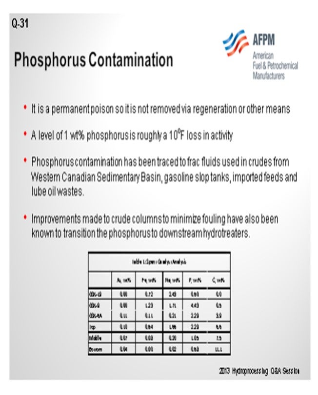
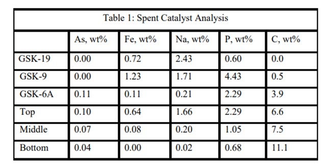
With phosphorus, there is the same problem. In this case, at about 1 wt% (weight percent) pickup, we see somewhere in the order of 10°F loss in activity. That number goes up as you get significant levels of phosphorus on the catalyst, but the first amount is not necessarily as important. On the bottom of the slide is a table showing a spent catalyst analysis from a reactor. You can see that this unit was able to pick up phosphorus even on some of our guard material. So, in some of our rings and support, you can actually pick up quite a bit of phosphorus. Again, that is related to temperature. It is also related to alumina surface area, similar to silicon trappings. So that should be your focus. Really, the amount of catalyst in your hydrotreater will determine where you define your need for dedicated trap material. We recommend spent catalyst analysis for looking at things like that.
SIVADASAN (UOP LLC, A Honeywell Company)
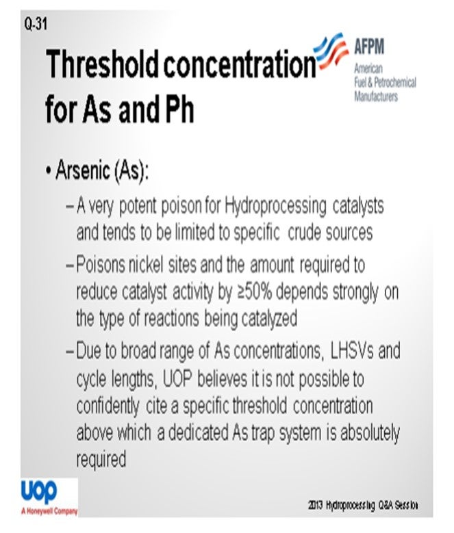
Arsenic is a poison for hydroprocessing catalysts and tends to be specific to crude sources. We have seen that how they apply to catalysts is mainly determined by the type of reactions being carried out. So for example, in a ULSD (ultra-low sulfur diesel) unit, if you see where an indirect hydrogenation route is the preferred part, then concentrations as low as 500 to 1,000 ppm (parts per million) of arsenic can affect the activity of the catalyst by more than 50%. But in a unit that is processing around 500 ppm of diesel, the catalyst will be able to withstand up to 1 wt% of arsenic before you see a 50% reduction of the life. Due to the broad range of arsenic concentrations, electro, and cycle lengths, we believe that it is not possible to confidentially cite a specific threshold concentration above where its dedicated arsenic trap system may be required.
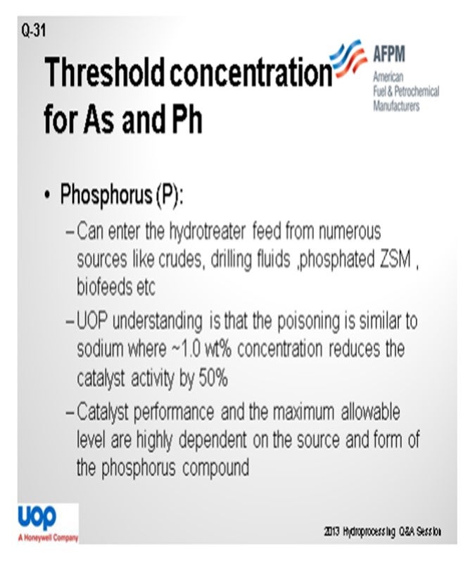
Phosphorus, again, can enter into the hydrotreater unit from various sources like crudes, drilling fluids, and phosphated trendsetters. They are the same biofeeds. We believe that the phosphorus generally tends to be quite similar to the sodium. Around 1 wt% of sodium may affect the activity of the catalyst by more than 50%. The catalyst performance and maximum allowable limit are highly dependent on the source and form of the phosphorus.
MUKESH PATEL (Reliance Industries Ltd.)
What is the Best Practice for analyzing arsenic and phosphorus? Should it be done weekly or on some other frequency? Because arsenic is very important when the crudes are changing every now and then, what should be the frequency and what is the industrial experience?
SIVADASAN (UOP LLC, A Honeywell Company)
The determination of arsenic is a bit difficult, as you pointed out, because it interferes a lot with the lab analysis. What people generally do is run a cycle, do a spent catalyst analysis, and then back-calculate how much amount of arsenic is in the feed.
MUKESH PATEL (Reliance Industries Ltd.)
When we say spent catalyst analysis, it is some sort of analysis of used catalyst, right? But what is a better predictive estimate we can do? Because when you want to capture, you can decide on some limit on the arsenic and then put in an arsenic trap. But if you keep putting on an arsenic trap, you will ultimately have a challenge because you will be compromising on cycle life. What I mean to say is that spent catalyst analysis is done after the completion of the cycles, which tells you what the true level of arsenic was in your feed. For example, suppose you are deciding about some loading for the new cycle and how to capture arsenic. Once you start putting in more and more arsenic traps or any demetallizing catalyst, you will be compromising the cycle because your volume will be less in the main catalyst. So, has there been any development where the conventional arsenic traps have a certain capacity for absorbing the arsenic? Is there any new development to help us capture three or four times the arsenic with the same type of volumes?
WATKINS [Advanced Refining Technologies (ART)]
The amount of trap will really depend on your main bed catalyst and your guard catalyst up at the top. If using a high-nickel catalyst, you could actually trade off and balance that activity; so you will maximize your cycle. If you have nickel catalyst in your entire reactor, you could extend your cycling because you can actually pick up a lot more arsenic that way. It is a constant battle, though, to define your cycle length and the amount of arsenic you can pick up. It is all dependent on temperature and how many pounds per day you are going to put in. I recommend that you work with your catalyst supplier to figure out an optimum system and what their products can actually hold without losing any activity or cycle length.
BRIAN WATKINS [Advanced Refining Technologies (ART)]
Arsenic
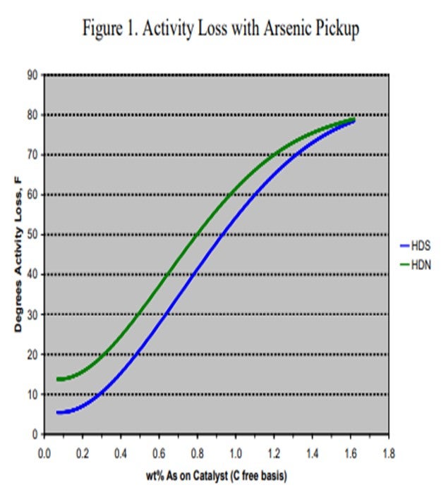
Arsenic (As) is found in many crudes including some from West Africa and Russia, as well as many synthetic crudes. It is becoming a common contaminant as use of these crudes, especially synthetic crudes, has been increasing in recent years. The arsenic is believed to bind with the metal sulfide sites (and in particular, the active nickel on the catalyst) forming nickel arsenide. This has a dramatic impact on catalyst activity. To demonstrate the effect of arsenic on catalyst activity, ART obtained a series of spent catalysts containing different levels of arsenic. These samples were carefully regenerated in the laboratory and were then activity tested using a diesel feed containing 50% cracked stocks under conditions producing less than 500 ppm sulfur. Figure 1 summarizes the results of that work. At 1,000 ppm, arsenic on the catalyst shows 5°F HDS (hydrodesulfurization) activity loss and nearly 15°F loss in HDN (hydrodenitrogenation) activity. The activity loss quickly increases to over 50°F with 1 wt% arsenic on the catalyst.
Canister data for a variety of catalysts also indicates that catalysts containing nickel are more effective for trapping arsenic. Figure 2 summarizes the arsenic pickup values for several NiMo (nickel molybdenum) catalysts. As this data shows, both high metals ULSD catalyst NDXi and AT580 as compared to our recent guard catalysts AT724G and AT734G, which are quite effective for trapping arsenic. The data also indicates that the active ring materials and demetallization catalysts used are also effective for trapping arsenic.
Other canister data also shows that the ultimate arsenic pickup is heavily dependent on temperature. Figure 3 shows the arsenic pickup as a function of temperature for a NiMo catalyst. These results were obtained by analyzing spent samples of a high metals NiMo catalyst from a three-reactor unit processing 100% cracked naphtha from a synthetic crude source. The first reactor was operated at very low temperature (about 275°F) in order to saturate diolefins. The second reactor was designed to saturate mono-olefins and operated at about 430°F. The last reactor had an inlet of 570°F and an outlet temperature of approximately 650°F. The arsenic content on the catalyst correlated with the temperature of the reactor as depicted in the figure. The data demonstrates that a high nickel catalyst can pick up very high arsenic levels if the operating temperature and feed concentration are high enough.
Noting that there are a wide range of arsenic levels, unit operating conditions, and expected cycle lengths, the ability to define a single-set threshold for when a trap is needed is difficult. It is recommended that if arsenic is found to be a problem contaminant, you will need to consult your supplier to determine if it is impacting the cycle and if and how much guard catalyst is needed.
Phosphorous
Phosphorous contamination in oil has been traced to fracturing fluids that are often used in crudes from the Western Canadian Sedimentary Basin. The source is diphosphate esters which are soluble in the crude oil. Refineries that run large percentages of light Western Canadian crude have reported crude column and crude furnace fouling for many years. Improvements made to crude columns to minimize fouling have transitioned the depositing of phosphorous to the downstream hydrotreaters.
Other sources of phosphorous include gasoline slop tanks, imported feeds, and lube oil wastes. If phosphorous does manage to make its way into the hydrotreater, it will poison the active sites of the catalyst causing a loss in activity. A level of 1 wt% of phosphorous on the catalyst results in roughly 10°F loss in activity. ART recommends that a feed content of less than 0.5 wppm (weight parts per million) be maintained whenever possible, as well as the use of feed filters to assist in trapping of phosphorous sediment.
An ART catalyst case study of the detrimental impacts of feed poisons on hydrotreater performance involved a ULSD unit which had recently started up with ART catalysts. Shortly after startup, the unit began to experience extremely rapid catalyst deactivation. It was so severe that within a couple months, the unit required an unplanned turnaround and the installation of fresh catalyst. Samples of spent catalyst representing the whole catalyst charge were collected and analyzed in the laboratory. The results are summarized in Table 1. It is apparent from these results that the catalysts were exposed to high levels of several poisons including arsenic, sodium, phosphorous, and iron. The contaminants penetrated well into the catalyst bed. Catalyst at the bottom of the reactor was not yet poisoned, but the coke content was extremely high for catalyst which had been onstream such a short time. The level of contaminants indicates the catalyst in the top half of the bed lost over 60°F of activity while the bottom was providing most of the HDS conversion. This required very high temperatures, which is reflected in the high carbon content at the bottom of the bed.
ART has a suite of options in order to protect the main bed from these and other contaminants which may be present in the feed to a typical hydrotreater. The use of several of these materials combined together can adequately provide protection and extend the cycle life of your hydrotreater.
RAJESH SIVADSAN (UOP LLC, A Honeywell Company)
Arsenic (As) is a very potent poison for hydroprocessing catalysts. Although As tends to be limited to specific crude sources (e.g., crudes from the U.S. and Canadian Rocky Mountains, Russian Urals, specific Chinese and West African sources, and “synthetic crudes” from Canada and Venezuela), it is usually present in all boiling fractions of those crudes.
Arsenic tends to poison the nickel sites of hydroprocessing catalyst, and the amount required to reduce catalyst activity by ≥50% depends strongly on the type of reactions being catalyzed. For instance, in diesel hydrotreating where ULSD is produced and product quality depends heavily on hydrogenation route desulfurization, as little as 500 to 1,000 wppm arsenic on catalyst can reduce HDS activity by 50%. On the other hand, for hydroprocessing applications where direct desulfurization is the primary mechanism for reaching product targets, higher levels of arsenic contamination on catalyst (about 1 wt% As) may be tolerated while retaining HDS activity greater than 50% of fresh catalyst activity.
Because of the broad range of as concentrations on catalyst that will poison the catalyst, as well as the broad ranges of LHSVs (liquid hourly space velocities) and cycle lengths for various hydroprocessing applications, UOP believes it is not possible to confidently cite a specific threshold concentration for as in feed above which a dedicated as trap system is absolutely required.
Phosphorus (P) can enter the hydrotreater feed from numerous sources: crudes, drilling fluids, phosphated ZSM (Zeolite Socony Mobil), phosphorus-based corrosion inhibitors and flow improvers, and biofeeds.
In one UOP commercial experience, about 3 wt% phosphorus on the catalyst terminated all the exotherm in the catalyst bed. Organic phosphorous can penetrate into catalyst pores. In general, our understanding is that the poisoning is similar to sodium where about 1.0 wt% concentration reduces the catalyst activity by 50%.
Based on UOP’s experience, we have found that the quantitative effects of phosphorus on hydroprocessing catalyst performance and the maximum allowable level are highly dependent on the source and form of the phosphorus compound, catalyst properties, and the process application, which all need to be considered when designing a trap system. Thus, UOP believes it is not really possible to confidently cite an absolute threshold concentration for phosphorus in feed above which a dedicated trap system is definitely required.
PER ZEUTHEN (Haldor Topsøe, Inc.)
Arsenic and phosphorous compounds are both known as permanent catalyst poisons; however, they each have very different deactivation mechanisms. Arsenic species found in the crude oil, particularly in the heavy ends, act as a true catalyst poison during titration of the nickel- or cobalt-promoted catalytically active sites. Although the concentration typically is rather low in ppb (parts per billion) levels, content of more than 50 ppb, for example, will have a significant negative impact on the catalyst performance. Arsenic compounds are very poisonous to the working catalysts, a typical high-activity catalyst has lost most activity after accumulation of as little as 1% As. Besides, shale oil and other new crude types (Russian and Canadian crudes) contain significant arsenic levels.
Haldor Topsøe has developed a number of dedicated arsenic pickup catalysts to protect the downstream bulk catalyst from very severe poison. The arsenic pickup capacity of this catalyst, TK-45, is as high as 10 wt%, but the actual pickup capacity will depend on the arsenic level in the feed and the operating temperature. With improved diffusion and preparation, Topsøe has recently launched a new dedicated arsenic trap, TK-49, with improved arsenic pickup for all hydrotreating applications.
Phosphorous species are rarely found in typical crudes; however, some opportunity crudes (and in particular, renewable feeds) often contain significant amounts of phosphorous. Moreover, phosphorous containing anti-corrosion additives can be found in the diesel and VGO (vacuum gas oil) fractions. The phosphorous compounds are decomposed in the hydrotreater, and the phosphates react with the alumina support, forming very stable alumina phosphates. Accumulated amounts of phosphates will reduce the accessibility to the active sites of hydrotreating catalysts and lower the activity accordingly.
Topsøe has a specialty product, TK-31, with a capacity of more than 5 to 6 wt% phosphorus, where reaction sites for phosphates have been improved the most. Topsøe recommends installing this phosphorous trap if the feed level is higher than 2 ppm phosphorus for protecting the downstream bulk catalyst from contamination.
Year
2013
Process