Question 62: Do you know of factors that are likely to lead to deposit formation on power recovery turbine blades? Is there anything that can be done to prevent these deposits from laying down on the blades? Once the deposits have been formed, what are the consequences and is there any way to remove the deposits online?
BHARGAVA (KBC Advanced Technologies, Inc.)
In summary, it is all about turbine blade deposition in the expander on the flue gas. First, I will talk about the causes, catalyst loading being the number one and the only cause for most of the turbine blade deposition. The catalyst loading on the flue gas inlet is what determines the amount of deposition. From a mechanical standpoint, the blade deposition increases as the performance of a third-stage separator goes down – for whatever reason – or the loss in regenerator cyclone efficiencies. From a catalyst perspective, if you are trying to put in a new catalyst, that catalyst will have different attrition properties. Evidence of mechanical damage in the unit that results in more catalyst fines will have the same effect. Increasing fresh catalyst additions will produce the same result, because fresh catalyst contains more fines. Also, as you start processing resid or heavy metal gasoil and your sodium and vanadium levels go up, the catalyst will start to get stickier and will create eutectic mixtures at certain temperatures, resulting in more catalyst sticking on the blades. From an operational standpoint, if you increase flue gas rates when you increase air rates, the amount of catalyst loss through the cyclones will increase and result in more deposition.
At some sites, we found additional steam being injected upstream of the expander, a practice that is done for different reasons. One reason could be to maintain temperature and pressure on the inlet of the expander in order to keep up the efficiencies, but that is not a recommended solution because it actually makes the situation worse on the turbo expander. So, those were the causes.

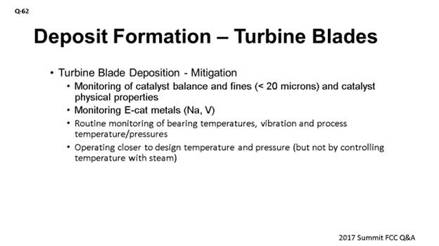
What is mitigation? It is important to understand the cause of the depositions. You want to make sure you analyze the deposits. If you do not have that luxury, then track the 20-microns or less size range, the catalyst’s physical properties, and monitor the e-cat metals. From a mechanical perspective, you want to do a routine monitoring of the bearing temperatures and vibration, and then check the process temperatures and pressures to identify if you are having a problem. One option to help reduce the turbine blade deposition is to run close to the design temperature and pressure.
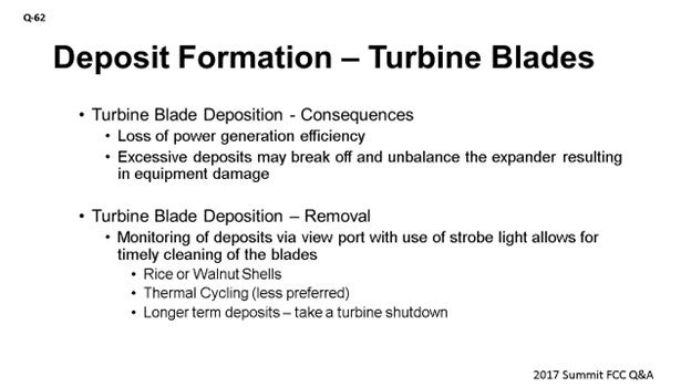
Consequences: These are obvious consequences. You lose power generation efficiency, but more serious are excessive depositions. If you have deposition on the blade and have uneven breaking off the deposits, the expander can become unbalanced, which goes back to the previous point about monitoring vibrations for early detection. How do people remove the deposits? First, you need to monitor the deposits via a viewport using a strobe light. This light will allow you to quickly detect the buildup of deposits. This monitoring is more important because if the deposit just builds up, it will be easier to remove the deposits. You can even do that with an online riser walnut shell cleaning. Some people have resorted to thermal cycling by bypassing the expander. Again, that is also a thermal shock to the unit, so we do not recommend it. Finally, if the deposits have been there for a long time, you do not have any choice but to shut down the expander.
FEDERSPIEL (W.R. Grace & Co.)
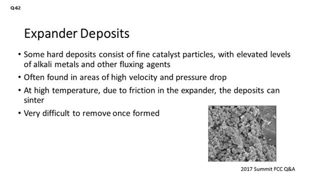
Like what was previously mentioned, some of the hard deposits that may form on the expander blades might consist of fine catalyst particles but may be enriched with other contaminants like sodium, potassium, calcium or chlorides, vanadium, iron, and other trace elements. The theory is that they might form a eutectic that drops out on areas of high velocity and pressure drop. It is a little counterintuitive; but the expander, of course, is one such place. Further, if you build up the deposit to a sufficient thickness where it starts to cause friction on the machine, those deposits can then be enriched with the expander metallurgy. And if they get hot enough, those deposits could then sinter and be very hard to remove.
So, one of the key takeaways is to send in the deposit for analysis. We can do chemical analysis and look at what material is actually there. There are more advanced techniques as well, like microprobe or line scanning, which can tell us where the different elements are lining up in that deposit or how they are formed over time. Even SEM (scanning electron microscopy) and X-ray diffraction can look at not just the shape of the deposit but can also identify crystal structure.

PUI-NANG LIN [Flint Hill Resources (FHR)]
Another area we found very important for the expander fouling is the quality of your expander cooling and impingement steam. That is another source of sodium that can accelerate the blade deposits.
ALEXIS SHACKLEFORD (BASF Corporation)
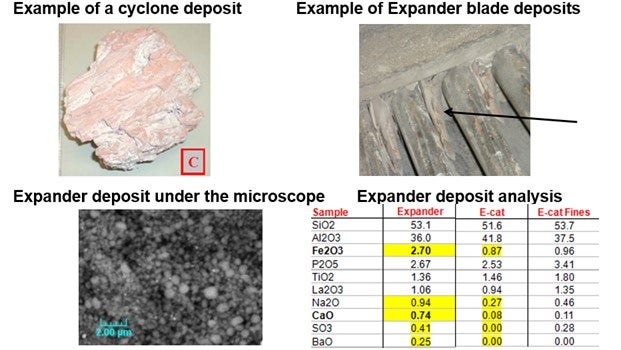
Another element you should look for is sulfur. Sulfur is often enriched in these deposits. Occasionally, you may also see evidence of refractory in these deposits. Please see BASF’s response in the Answer Book that shows you what these deposits look like compared to e-cat and compared to fines samples.
MELIKE YERSIZ (Chevron U.S.A., Inc.)
How often do you recommend inspecting the blades with the strobe lights?
BHARGAVA (KBC Advanced Technologies, Inc.)
If you have a viewport in a strobe light, then you should be routinely monitoring the blades once every couple of weeks, depending on the severity of the situation. You can then increase or reduce the frequency, depending on how your deposition goes.
FEDERSPIEL (W.R. Grace & Co.)
When I worked at Hovensa, we would do it weekly. We often found out that staying ahead of the problem was a lot easier than trying to address it after it became an issue. So, if you have the facilities there that look to the viewport or take the pictures, it is probably easiest to set it up on a regular basis – like on Saturday – just to have the Inspection guys go out, take the pictures, and monitor it.
PHILLIP NICCUM (KP Engineering, LP)
I want to make a reference to a paper written by David Linden with Ingersoll Rand back in the 1980s. The topic of the paper was the composition of these deposits. It is a seminal work on this subject, and I recommend it. In the paper is a reference to tables of these eutectic mixtures, and I have some of them. It is pages and pages of eutectic mixtures with many elements from FCC with which you are very familiar. It is quite a useful reference.30
BOB LUDOLPH [Shell Global Solutions (US) Inc.]
Calcium and iron also play into those eutectics as well and can have a dramatic effect. As far as the sodium goes, make sure your desalter is being checked for its effectiveness, because a dramatic shift in its performance could really result in a much larger change in the expander operation.
SANJAY BHARGAVA (KBC Advanced Technologies)
Deposit formation is usually linked to catalyst depositing on the turbine blades. The deposits are mostly a function of catalyst loading of the inlet flue gas. An increase in catalyst loading could be due to several factors, including performance of the third-stage separator, loss in cyclone efficiency, change in catalyst attrition properties, excess fines in fresh catalyst, an increase in fresh catalyst additions, and/or an increase in flue gas rates due to higher air rates.
In addition, KBC has seen locations where steam is introduced between the regenerator outlet and tunable diode laser spectroscopy third-stage separator. The addition of steam is used to control the temperature within the guidelines of the expander. The use of steam and the added “humidity” increase the deposition potential of the catalyst on the blades. Further, high levels of sodium and vanadium on equilibrium catalyst can also form a sticky, eutectic mixture which would tend to stick to the blades more easily and lead to accelerated deposition rates.
Rigorous monitoring of catalyst balance and fines generation – specifically, sub-20-micron particles – helps us understand the deposition rate on the blades. Minimizing deviations from design pressure and temperature also helps reduce the rate of deposition. Monitoring catalyst physical properties and Na/V (sodium/vanadium) to ensure good cyclone efficiencies is as important. Early or regular action to correct the deposition problem by routine monitoring of bearing temperatures and vibration, along with process temperature and pressure, will provide the required information for corrective course of action.
Deposits can be monitored via a view port with a strobe light to allow weekly photographing of the blades. This information can then be used to establish the frequency of regular online cleaning of the blades. Cleaning can be done with rice, walnut shells, or a less preferred method of thermal cycling of the turbine by partial bypassing of the flue gas to cool down the blades. If the deposits are allowed to build up over extended time periods, online cleaning is not recommended as chunks of deposits are likely to be removed non-uniformly, which can unbalance the blades and result in excessive vibration.
MICHAEL FEDERSPIEL (W.R. Grace & Co.)
The paper, “Catalyst Deposition in FCCU Power Recovery Systems” by David H. Linden31 at Ingersoll-Rand, refers to four types of deposits that occur in flue gas lines, equipment, and power recovery turbines. The first type (A) are powdery catalyst deposits that cling to surfaces in the flue gas train. The second type (B) occurs when those powdery catalyst deposits get wet and then harden after drying out. Upon analysis, these deposits appear similar in chemical makeup to equilibrium catalyst or third-stage separator fines.
The third type (C) of deposit is made up of very small catalyst particles, along with elevated levels of alkali metals (sodium, potassium, and calcium), chlorides, vanadium, and iron, as well as other trace contaminants from unique or challenging feedstocks. It is theorized that these contaminants form a low melting point eutectic. These deposits are very hard and are often found in areas of high gas velocity and pressure drop, and the expander is just such a place. If these deposits form along the expander blade tips to sufficient thickness to cause rubbing, the friction will increase the temperature enough to sinter the deposit into a new type (D) of deposit which has increased metals content from the expander metallurgy.
By reducing catalyst traffic to the flue gas and preventing condensation, these types of deposits can be minimized. Keeping the regenerator cyclones and third-stage separator mechanically healthy and operating within design specifications will help. Ensuring catalyst coolers are leak-free will prevent boiler feed water chemicals from further contaminating catalyst and eliminate an attrition source. Running the expander at design conditions can keep the flow path through the expander fully developed, thus mitigating eddy currents and dead spaces. Suppressing the contaminant metals (particularly those that accumulate on the surface of the catalyst particle and then abrade off) or using a catalyst with a low attrition tendency can help to reduce blade depositions. There are also several options for expander coatings which can reduce or prevent the accumulation of deposits.
Monitoring deposits during the run can help a refiner be prepared for work that needs to be done during the next available outage. Taking pictures through view ports and vibration monitoring are two common methods used to quantify and track deposit formation.
Once formed, deposits can cause loss of expander efficiency and threaten the mechanical integrity of the machine, as well as force a shutdown due to high vibrations. While these deposits can be removed through the injection of walnut shells or rice, a regular program aimed at preventing the formation of deposits is generally more effective at achieving longer run lengths than attempting to fix a vibration issue after it develops. Varying the size of the media can help reach the different places these deposits form. Other methods include thermal shocking or thermal cycling of the expander, which takes advantage of the different thermal expansion coefficients of the deposits and the turbine metallurgy to release accumulated deposits from the surface of the blades.
ALEX MANNION (BASF Corporation)
Below are deposit examples from a cyclone and expander blade. Typically, these deposits are rich in elements such as Fe (iron), Ca, Na, Mg and S. These elements can act as a “glue,” binding catalyst fines together.
Factors that could lead to deposit formation include high catalyst attrition, high catalyst losses from cyclones, poor water quality being used from steam injection, water condensation and precipitation at cold spots, and high metals content in the FCC feed.
Several measures can be taken to avoid deposits from laying down on the blades. To minimize fines generation, an attrition-resistant catalyst can be used, and fresh catalyst additions should be minimized. Also, all steam ROs (restriction orifices) should be in place, and excess velocities should be avoided. High-quality water should always be used while minimizing water injection, when possible. “Cold spots” in the overhead line or expander should be avoided. Crude desalting additives can be used to minimize metals (e.g., Ca) in the feed. Finally, effective soot blowing of CO boiler tubes can mitigate deposit formation as well.
Deposits can lead to expander vibrations and blade erosion, potentially leading to catastrophic equipment failure. If deposits have begun to form, regular walnut shell cleaning can be conducted and thermal spalling if required.
Year
2017
Process
Question 18: Vacuum Gas Oil (VGO) Hydrotreaters are being pushed to process heavier feeds while maximizing Fluidized Catalytic Cracking Unit (FCCU) performance while meeting Tier III gasoline specifications. How are you balancing increased severity and cycle length? What considerations do you give to feed quality and upstream unit operations?
JEFF CATON (Axens)
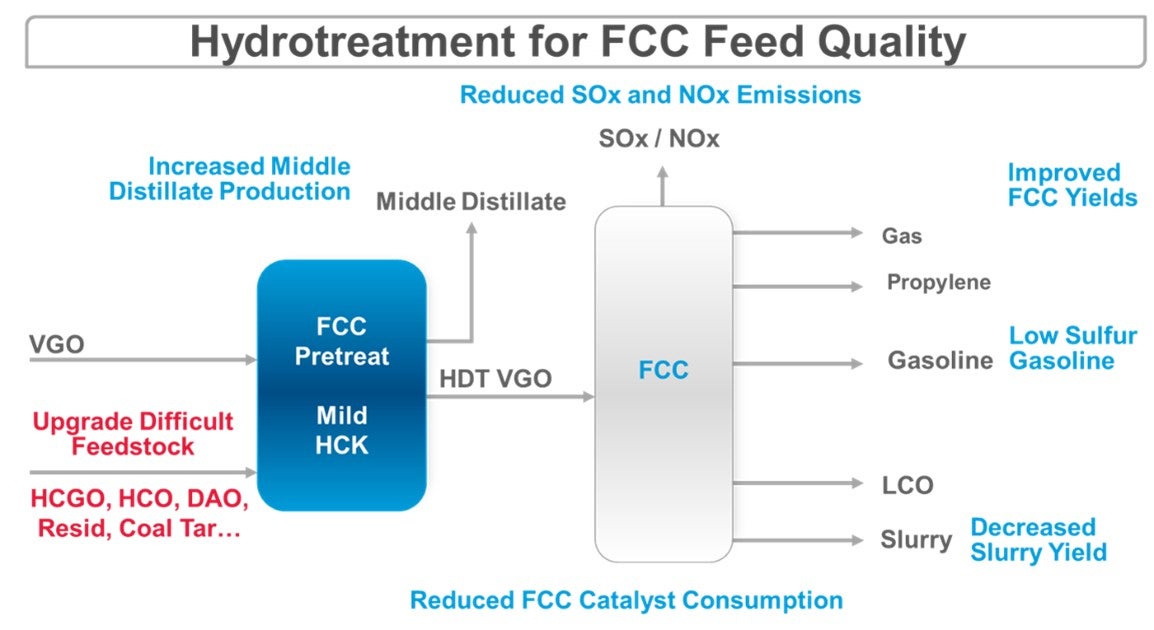
The FCC unit has long been the workhorse in the refinery to achieve relatively low-cost conversion of heavy crude components (VGO, HCGO and some atmospheric residue) into gasoline, butenes for high-octane alkylate production, propylene and LCO diesel blend components (Refer to Figure 1 - FCC Pretreatment Primary Objectives). The benefits of FCC feed pretreatment or VGO hydrotreating (CFHT) are well known; improved FCC performance and yields, decreased FCC product sulfur (with the potential to produce ultra-low sulfur gasoline), increased volume swell through aromatics saturation, and decreased FCC SOx and NOx emissions. When considering the importance of environmental compliance, crude slate flexibility, and optimizing product yields, the CFHT performance and reliability plays a tremendous role in the overall profitability of the refinery.
Figure 1 - FCC Pretreatment Primary Objectives
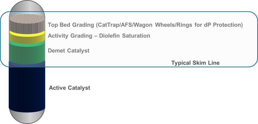
With increased sweet-sour spreads, the onset of Tier 3 gasoline regulations, and strong gasoline export demand, there has been a resulted decrease in CFHT feed quality primarily via increases in deasphalted oil (DAO), heavy coker gasoil (HCGO), and higher sulfur feedstocks coming to the CFHT. These feedstocks contain significant amounts of hydrogen-deficient compounds, refractive sulfur and nitrogen species, and metals, which need to be hydrotreated by the CFHT before being fed to the FCC. If not properly treated in the CFHT, the FCC performance, FCC yields, and FCC gasoline sulfur will suffer. To treat properly, requires a careful selection of the CFHT catalytic system to consider the potential for higher metals (nickel, vanadium, arsenic, silicon) and asphaltenes, along with the higher fouling propensity of these aromatic-rich feeds. In addition, a high activity and high stability active catalyst will be required to achieve the desired HDS, HDN, and HDA levels while maximizing cycle length. Even with a carefully selected catalytic system, the CFHT will likely have to be run at a higher operational severity, thus yielding a shortened CFHT cycle length. It is not uncommon that the CFHT cycle length cannot be stretched to coincide with the FCC turnaround interval, thus becoming necessary to have a CFHT catalyst changeout mid-FCC turnaround cycle. The refiner will need to consider possible scenarios for mid-FCC turnaround cycle CFHT full catalyst changeouts. Alternatively, it may be possible to span the FCC turnaround cycle with one or multiple CFHT catalyst skims, including replacement of top bed grading, activity grading, and demetallization catalyst (Refer to Figure 2 - Skim of Top Bed Grading/Activity Grading/Demet).
Figure 2 - Skim of Top Bed Grading/Activity Grading/Demet
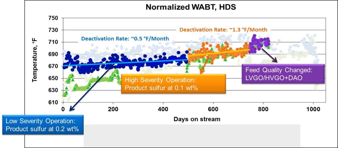
For refiners with a CFHT and FCC gasoline post-treatment unit, there is a possibility to gain a distinct advantage by optimizing the balance between CFHT and post-treatment severity to maximize cycle lengths and FCC yields while minimizing pool octane loss. In addition, a refiner should consider if it is economically optimal to run the CFHT in maximum HDA mode (higher temperature leading to over treating of sulfur) early in the cycle followed by operations in HDS mode later in the cycle. This will be highly dependent on the hydrogen supply affordability and availability and the CFHT catalytic system utilized. Optimization of the CFHT, FCC, and post-treatment units has been accomplished via rigorous simulation of incremental DAO lift-barrels, CFHT severity vs. cycle length, the corresponding FCC yields, and post-treatment octane loss. A deep understanding of the feedstocks and the chemical reactions involved in CFHT (kinetics, thermodynamics, contamination/poisoning) is of key importance. As many of these factors’ responses are non-linear, utilizing existing LP models is not always the solution, and dedicated optimization work has provided the most complete solution. Process technology licensors and catalyst suppliers may act as consultants in this optimization effort. Further, catalyst suppliers can provide regular unit and catalyst health monitoring support to enable better utilization of the full catalyst life. As illustrated in this example (Refer to Figure 3 - Monetizing Full Catalyst Life), knowing that there would be unused catalyst life remaining at the scheduled changeout time, the refiner was able to increase CFHT operating severity first decreasing product sulfur and subsequently increasing DAO feed rate and LVGO/HVGO feed endpoint in order to monetize the full catalyst life.
Figure 3 - Monetizing Full Catalyst Life
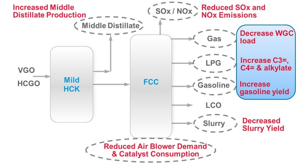
There may also be an opportunity to increase the severity of the CFHT, not only to meet sulfur targets and increase volume swell, but also to change the diesel-to-gasoline ratio by operating the CFHT in mild hydrocracking (MHC) mode (Refer to Figure 4 - Mild Hydrocracking in a CFHT). Given the pending IMO 2020 regulations, increasing diesel-to-gasoline ratio for increased production of low-sulfur diesel for (LSD), which could be used for blending bunker to low-sulfur fuel oil (LFSO), or production of ultra-low sulfur diesel (ULSD) may be highly profitable. These adjustments will require some modifications to the operating conditions, selection of the optimum catalytic system and distributor internals, increased hydrogen consumption and likely upgrades throughout the unit. One of the challenges of operating in the MHC mode is the ability to meet ULSD specifications throughout the MHC cycle. Moderate-pressure MHC units generally do not meet the required ULSD specifications, therefore post-treatment is typically required. Production of LSD may be a more economical target.
ROBERT STEINBERG (Motiva Enterprises)
If only a portion of the FCCU feed is hydrotreated it can be helpful to increase VGO hydrotreater charge rate to minimize high sulfur feeds to the FCCU. Reducing VGO hydrotreater severity may be required at higher charge rates, especially if you are trying to maintain a reasonable catalyst life. Lower severity at higher charge rates will generally mean more total pounds of sulfur is removed which minimizes total sulfur to the FCCU. Removing more total sulfur will also generally remove more nitrogen and saturate more aromatics which will increase FCCU conversion as well as making it easier to meet Tier III requirements.
For example, if a VGO hydrotreater was removing 93% of the feed sulfur and the charge rate was increased 20% with the same feed quality while the reactor temperature was adjusted to maintain run life, the desulfurization would be expected to be reduced to about 88%. This would remove about 14% more pounds of sulfur from the FCCU feed while maintaining CFH catalyst life.
The same concept would apply if the hydrotreater needed to process heavier feeds. If more difficult feeds were routed to the same hydrotreater without increasing charge rate or adjusting reactor temperature, the percent desulfurization would stay about the same. Even though the product sulfur would increase, more sulfur would be removed, and catalyst life would be about the same. If the some of the FCCU feed is hydrotreated and some goes to the FCCU without pretreatment, the heaviest highest sulfur feeds should be sent to the hydrotreater.
Balancing hydrotreater severity and cycle length is site specific. Ideally, the hydrotreater catalyst life should match the FCCU turnaround cycle to avoid having to shutdown the hydrotreater while the FCCU operates. This will often not be feasible at reasonable severities. But adjusting severity to do one or two cat changes during between turnarounds may be practical. When doing this it can be helpful to establish a temperature budget for the hydrotreater cycle and stick to that budget even if feed conditions change, provided enough sulfur is being removed to keep the FCCU naphtha sulfur on target. Product sulfur may fluctuate from day to day but will be reasonably constant and as low as reasonably practical throughout the cycle.
Alternatively, the CFH WABT can be maintained at the aromatic saturation limit to maximize aromatic saturation throughout the run. By not exceeding the temperature at which aromatic saturation starts to decrease, rapid catalyst aging is avoided. This will tend to give the maximum FCCU conversion throughout the cycle but FCCU feed sulfur will start low at SOR and gradually increase through the run as the CFH catalyst ages. This can be particularly attractive if the FCCU sulfur stays low enough to meet Tier III requirements without penalty throughout the run.
During hydrotreater catalyst changes it may be necessary to reduce the FCCU charge rate to still be able to make Tier III gasoline. Temperature budgets can be adjusted to have the hydrotreater catalyst changes occur at desired times such as when refinery throughput and FCCU charge rates are reduced for other reasons or during months when there is lower gasoline demand.
ARAVINDAN KANDASAMY (UOP)
Cycle length of typical Vacuum Gas Oil (VGO) Hydrotreating unit is shorter (ranging from one to two years) than that of typical FCC unit. Performance of FCC impacts the profitability of most refineries around the world. Therefore, refineries alter the Vacuum Gas Oil (VGO) Hydrotreating operation to match with FCC turnaround schedules and will have limited scope to compromise cycle length of VGO HT.
The metal contaminants and asphaltenes in the feed to a Vacuum Gas Oil (VGO) Hydrotreating Unit can limit the cycle length more than the product quality specification. Though the catalyst technology used in VGO hydrotreating units have improved continuously & considerably over the years, the refiners frequently balance the increased operating severity with some operational changes to maintain the required cycle length. Some of the operational changes widely used are.
-
Marginally reducing endpoint of VGO to keep metals and asphaltenes under control (or)
-
Increasing the use of deasphalting unit to increase endpoint of VGO HT feed.
-
Adding lead-lag mode of demetallization catalyst beds
-
Optimizing mix of Demet with Active hydrotreating catalysts
-
Increasing hydrogen purity across the Vacuum Gas Oil (VGO) Hydrotreating unit with Pressure Swing Adsorption (PSA) membrane technologies
-
Improved stacking of hydrotreating activity based on prevailing H2 partial pressure.
While the capacity of demetalization catalysts to trap more variety and quantity of metals has increased appreciably, handling asphaltenes and Conradson Carbon remains a challenge for a unit operating at a limited hydrogen partial pressure. Feeds derived from opportunistic crudes have more asphaltene and Conradson Carbon than typical crudes. Moreover, asphaltenes and Conradson Carbon from various sources differ in their impact. For example, asphaltenes and Conradson Carbon of from Heavy Coker Gas Oil (HCGO) is more difficult to handle than those from Heavy Vacuum Gas Oil (HVGO). So appropriately adjusting the cut points of individual feed components are essential to maintain overall feed quality. Refineries are rapidly adapting advanced feed characterization with data analytics to continuously optimize feed blend (crude source & unit source) to get the best out of Vacuum Gas Oil Hydrotreating units while achieving desired cycle length.
Overall refinery specific & cycle specific objectives and constraints must be considered to select the appropriate catalyst solution for VGO HT units.
Year
2018
Process