Question 62: Do you know of factors that are likely to lead to deposit formation on power recovery turbine blades? Is there anything that can be done to prevent these deposits from laying down on the blades? Once the deposits have been formed, what are the consequences and is there any way to remove the deposits online?
BHARGAVA (KBC Advanced Technologies, Inc.)
In summary, it is all about turbine blade deposition in the expander on the flue gas. First, I will talk about the causes, catalyst loading being the number one and the only cause for most of the turbine blade deposition. The catalyst loading on the flue gas inlet is what determines the amount of deposition. From a mechanical standpoint, the blade deposition increases as the performance of a third-stage separator goes down – for whatever reason – or the loss in regenerator cyclone efficiencies. From a catalyst perspective, if you are trying to put in a new catalyst, that catalyst will have different attrition properties. Evidence of mechanical damage in the unit that results in more catalyst fines will have the same effect. Increasing fresh catalyst additions will produce the same result, because fresh catalyst contains more fines. Also, as you start processing resid or heavy metal gasoil and your sodium and vanadium levels go up, the catalyst will start to get stickier and will create eutectic mixtures at certain temperatures, resulting in more catalyst sticking on the blades. From an operational standpoint, if you increase flue gas rates when you increase air rates, the amount of catalyst loss through the cyclones will increase and result in more deposition.
At some sites, we found additional steam being injected upstream of the expander, a practice that is done for different reasons. One reason could be to maintain temperature and pressure on the inlet of the expander in order to keep up the efficiencies, but that is not a recommended solution because it actually makes the situation worse on the turbo expander. So, those were the causes.

What is mitigation? It is important to understand the cause of the depositions. You want to make sure you analyze the deposits. If you do not have that luxury, then track the 20-microns or less size range, the catalyst’s physical properties, and monitor the e-cat metals. From a mechanical perspective, you want to do a routine monitoring of the bearing temperatures and vibration, and then check the process temperatures and pressures to identify if you are having a problem. One option to help reduce the turbine blade deposition is to run close to the design temperature and pressure.
Consequences: These are obvious consequences. You lose power generation efficiency, but more serious are excessive depositions. If you have deposition on the blade and have uneven breaking off the deposits, the expander can become unbalanced, which goes back to the previous point about monitoring vibrations for early detection. How do people remove the deposits? First, you need to monitor the deposits via a viewport using a strobe light. This light will allow you to quickly detect the buildup of deposits. This monitoring is more important because if the deposit just builds up, it will be easier to remove the deposits. You can even do that with an online riser walnut shell cleaning. Some people have resorted to thermal cycling by bypassing the expander. Again, that is also a thermal shock to the unit, so we do not recommend it. Finally, if the deposits have been there for a long time, you do not have any choice but to shut down the expander.
FEDERSPIEL (W.R. Grace & Co.)
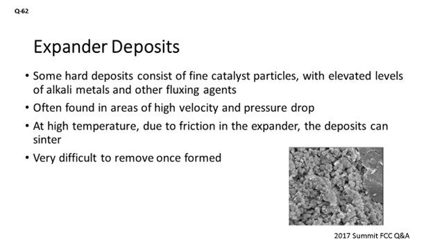
Like what was previously mentioned, some of the hard deposits that may form on the expander blades might consist of fine catalyst particles but may be enriched with other contaminants like sodium, potassium, calcium or chlorides, vanadium, iron, and other trace elements. The theory is that they might form a eutectic that drops out on areas of high velocity and pressure drop. It is a little counterintuitive; but the expander, of course, is one such place. Further, if you build up the deposit to a sufficient thickness where it starts to cause friction on the machine, those deposits can then be enriched with the expander metallurgy. And if they get hot enough, those deposits could then sinter and be very hard to remove.
So, one of the key takeaways is to send in the deposit for analysis. We can do chemical analysis and look at what material is actually there. There are more advanced techniques as well, like microprobe or line scanning, which can tell us where the different elements are lining up in that deposit or how they are formed over time. Even SEM (scanning electron microscopy) and X-ray diffraction can look at not just the shape of the deposit but can also identify crystal structure.

PUI-NANG LIN [Flint Hill Resources (FHR)]
Another area we found very important for the expander fouling is the quality of your expander cooling and impingement steam. That is another source of sodium that can accelerate the blade deposits.
ALEXIS SHACKLEFORD (BASF Corporation)
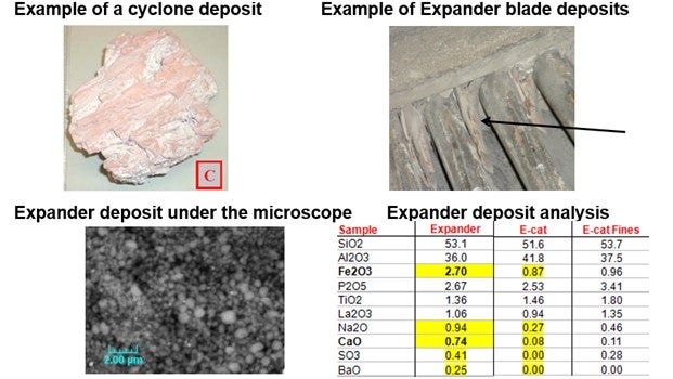
Another element you should look for is sulfur. Sulfur is often enriched in these deposits. Occasionally, you may also see evidence of refractory in these deposits. Please see BASF’s response in the Answer Book that shows you what these deposits look like compared to e-cat and compared to fines samples.
MELIKE YERSIZ (Chevron U.S.A., Inc.)
How often do you recommend inspecting the blades with the strobe lights?
BHARGAVA (KBC Advanced Technologies, Inc.)
If you have a viewport in a strobe light, then you should be routinely monitoring the blades once every couple of weeks, depending on the severity of the situation. You can then increase or reduce the frequency, depending on how your deposition goes.
FEDERSPIEL (W.R. Grace & Co.)
When I worked at Hovensa, we would do it weekly. We often found out that staying ahead of the problem was a lot easier than trying to address it after it became an issue. So, if you have the facilities there that look to the viewport or take the pictures, it is probably easiest to set it up on a regular basis – like on Saturday – just to have the Inspection guys go out, take the pictures, and monitor it.
PHILLIP NICCUM (KP Engineering, LP)
I want to make a reference to a paper written by David Linden with Ingersoll Rand back in the 1980s. The topic of the paper was the composition of these deposits. It is a seminal work on this subject, and I recommend it. In the paper is a reference to tables of these eutectic mixtures, and I have some of them. It is pages and pages of eutectic mixtures with many elements from FCC with which you are very familiar. It is quite a useful reference.30
BOB LUDOLPH [Shell Global Solutions (US) Inc.]
Calcium and iron also play into those eutectics as well and can have a dramatic effect. As far as the sodium goes, make sure your desalter is being checked for its effectiveness, because a dramatic shift in its performance could really result in a much larger change in the expander operation.
SANJAY BHARGAVA (KBC Advanced Technologies)
Deposit formation is usually linked to catalyst depositing on the turbine blades. The deposits are mostly a function of catalyst loading of the inlet flue gas. An increase in catalyst loading could be due to several factors, including performance of the third-stage separator, loss in cyclone efficiency, change in catalyst attrition properties, excess fines in fresh catalyst, an increase in fresh catalyst additions, and/or an increase in flue gas rates due to higher air rates.
In addition, KBC has seen locations where steam is introduced between the regenerator outlet and tunable diode laser spectroscopy third-stage separator. The addition of steam is used to control the temperature within the guidelines of the expander. The use of steam and the added “humidity” increase the deposition potential of the catalyst on the blades. Further, high levels of sodium and vanadium on equilibrium catalyst can also form a sticky, eutectic mixture which would tend to stick to the blades more easily and lead to accelerated deposition rates.
Rigorous monitoring of catalyst balance and fines generation – specifically, sub-20-micron particles – helps us understand the deposition rate on the blades. Minimizing deviations from design pressure and temperature also helps reduce the rate of deposition. Monitoring catalyst physical properties and Na/V (sodium/vanadium) to ensure good cyclone efficiencies is as important. Early or regular action to correct the deposition problem by routine monitoring of bearing temperatures and vibration, along with process temperature and pressure, will provide the required information for corrective course of action.
Deposits can be monitored via a view port with a strobe light to allow weekly photographing of the blades. This information can then be used to establish the frequency of regular online cleaning of the blades. Cleaning can be done with rice, walnut shells, or a less preferred method of thermal cycling of the turbine by partial bypassing of the flue gas to cool down the blades. If the deposits are allowed to build up over extended time periods, online cleaning is not recommended as chunks of deposits are likely to be removed non-uniformly, which can unbalance the blades and result in excessive vibration.
MICHAEL FEDERSPIEL (W.R. Grace & Co.)
The paper, “Catalyst Deposition in FCCU Power Recovery Systems” by David H. Linden31 at Ingersoll-Rand, refers to four types of deposits that occur in flue gas lines, equipment, and power recovery turbines. The first type (A) are powdery catalyst deposits that cling to surfaces in the flue gas train. The second type (B) occurs when those powdery catalyst deposits get wet and then harden after drying out. Upon analysis, these deposits appear similar in chemical makeup to equilibrium catalyst or third-stage separator fines.
The third type (C) of deposit is made up of very small catalyst particles, along with elevated levels of alkali metals (sodium, potassium, and calcium), chlorides, vanadium, and iron, as well as other trace contaminants from unique or challenging feedstocks. It is theorized that these contaminants form a low melting point eutectic. These deposits are very hard and are often found in areas of high gas velocity and pressure drop, and the expander is just such a place. If these deposits form along the expander blade tips to sufficient thickness to cause rubbing, the friction will increase the temperature enough to sinter the deposit into a new type (D) of deposit which has increased metals content from the expander metallurgy.
By reducing catalyst traffic to the flue gas and preventing condensation, these types of deposits can be minimized. Keeping the regenerator cyclones and third-stage separator mechanically healthy and operating within design specifications will help. Ensuring catalyst coolers are leak-free will prevent boiler feed water chemicals from further contaminating catalyst and eliminate an attrition source. Running the expander at design conditions can keep the flow path through the expander fully developed, thus mitigating eddy currents and dead spaces. Suppressing the contaminant metals (particularly those that accumulate on the surface of the catalyst particle and then abrade off) or using a catalyst with a low attrition tendency can help to reduce blade depositions. There are also several options for expander coatings which can reduce or prevent the accumulation of deposits.
Monitoring deposits during the run can help a refiner be prepared for work that needs to be done during the next available outage. Taking pictures through view ports and vibration monitoring are two common methods used to quantify and track deposit formation.
Once formed, deposits can cause loss of expander efficiency and threaten the mechanical integrity of the machine, as well as force a shutdown due to high vibrations. While these deposits can be removed through the injection of walnut shells or rice, a regular program aimed at preventing the formation of deposits is generally more effective at achieving longer run lengths than attempting to fix a vibration issue after it develops. Varying the size of the media can help reach the different places these deposits form. Other methods include thermal shocking or thermal cycling of the expander, which takes advantage of the different thermal expansion coefficients of the deposits and the turbine metallurgy to release accumulated deposits from the surface of the blades.
ALEX MANNION (BASF Corporation)
Below are deposit examples from a cyclone and expander blade. Typically, these deposits are rich in elements such as Fe (iron), Ca, Na, Mg and S. These elements can act as a “glue,” binding catalyst fines together.
Factors that could lead to deposit formation include high catalyst attrition, high catalyst losses from cyclones, poor water quality being used from steam injection, water condensation and precipitation at cold spots, and high metals content in the FCC feed.
Several measures can be taken to avoid deposits from laying down on the blades. To minimize fines generation, an attrition-resistant catalyst can be used, and fresh catalyst additions should be minimized. Also, all steam ROs (restriction orifices) should be in place, and excess velocities should be avoided. High-quality water should always be used while minimizing water injection, when possible. “Cold spots” in the overhead line or expander should be avoided. Crude desalting additives can be used to minimize metals (e.g., Ca) in the feed. Finally, effective soot blowing of CO boiler tubes can mitigate deposit formation as well.
Deposits can lead to expander vibrations and blade erosion, potentially leading to catastrophic equipment failure. If deposits have begun to form, regular walnut shell cleaning can be conducted and thermal spalling if required.