
Question 13: What are the typical causes for failing JFTOT and aviation turbine (AVTUR) specifications?
GROPP (GE Water & Process Technologies)
Assuming the jet fuel is on-spec with regard to other quality parameters, with the exception of perhaps copper strip corrosion and mercaptan sulfur, we have found that instability reaction precursors and catalysts are typically the root causes of JFTOT failures. These precursors include reactive hydrocarbons, especially olefins and aromatics, that might be found in coker distillates; sulfur compounds including H2S (hydrogen sulfide), mercaptans, and thiophenols; cyclical nitrogen compounds including indoles, pyrroles, and carbazoles; phenols; some acids, primarily naphthenic acids and light carboxylic acids; and then finally, catalysts in the form of transition metals, particularly copper and iron. Parts per billion (ppb) levels of copper are known to initiate and accelerate instability reactions that can cause jet fuel to fail the JFTOT. The sources are the crude oil itself, as well as refinery slops, heat exchanger leaks, and reactive blend components.
What are solutions to the problem? Source control is always the first line of defense, so careful attention to crude selection and blending, refinery slop management and minimization, and reactive blend component management are very important. Finally, good maintenance programs are essential to ensure that there are no leaks in exchangers that can cross-contaminate the product.

Even with good source control, trace contaminants in the fuel can cause problems. As a result, most of the refiners with whom we work utilize some kind of hydrotreating and/or caustic extraction and/or sweetening process in combination with a variety of waterwashes, drying equipment, and filtration steps. I cannot remember seeing two systems that contain exactly the same combination of equipment; so, from memory, I drew what might be a common or typical flow diagram. The equipment in my drawing includes a caustic extraction/sweetening unit, waterwash, water coalescer, salt dryer, and clay filter.
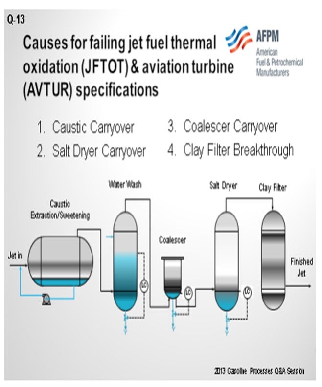
The number one cause of JFTOT failures that we see is caustic and contaminant carryover from the caustic extraction unit due to overspending the caustic and buildup of acid-suspended oils as measured in the UOP 743 test. When the level gets to about 30 to 40% acid-suspended oils, the caustic tends to emulsify with the jet fuel and carryover into the filtering and drying equipment. Sometimes contaminants end up in the jet fuel, and then the contaminated fuel fails the test. The key to preventing carryover is good caustic maintenance in the units to keep the suspended oils at a lower level: in the 30 to 40% spending range. That is our experience.
In addition, salt dryers can be a problem. There are two typical issues that we see. One is that the salt dryers are initially undersized, which results in carryover. The other is that the dryers have been in place and in service for many years, and throughput has increased compared to the initial design flow, resulting in carryover.
Other troubles associated with salt dryers include inlet fuel temperatures above design specifications, level control problems, and poor salt maintenance. I have seen a lot of salt dryers that do not have salt in them; and believe it or not, you must have salt in the vessels for them to work.
We have seen a few problems with the coalescer units. Typically, the concerns are associated with failed coalescer elements or level control.
Finally, the clay filter units can be problematic. The clay filter unit is designed to polish off the final trace contaminants in the fuel. Contaminants will build up in the filters and eventually break through if the clay is not replaced at the proper intervals. Even during normal operations, the caustic and clay must be replaced in proportion to the amount of contaminant loading in a jet fuel stream. Caustic unit, waterwash, coalescer, and salt dryer carryovers can also result in clay breakthrough and contamination.
Even with great source control and operation of the finishing processes, jet fuel sometimes still will not pass the JFTOT. In some of these cases, we have found approved antioxidants and metal deactivators to be effective in bringing the fuel back on-spec.
FRANKLIN WHEELER (Tesoro Corporation)
Going forward, the refining industry will have increased pressure to make jet and distillate versus gasoline as we biofuels have more market share. There are indications of that now throughout the U.S. The refining industry needs to be cognizant of operating windows in our fractionators, especially where you have hot drums on the overhead reflux system in your crude towers. They must be kept hot. Do not violate those operating windows at the expense of a jet production. Water can start to get reintroduced through the reflux system and cause corrosion. Several refiners began seeing the formation of copper corrosion after being overzealous to make increased jet yield. So, ensuring that operating windows are being met is a really critical part of making sure of your JFTOT quality stays on test. Also, the airlines do not like to use the metal deactivator; that is not the salvation. After a while, they will become concerned.
JESSY TRUCKO (UOP LLC, A Honeywell Company)
Keep in mind that if you have this recent change in any kind of corrosion inhibitors upstream, it can sometimes throw off your JFTOT. Mixing delta pressure across your mixing valves for your electrostatic precipitator or too high-percent spent caustic will increase emulsions; and once you start forming emulsions in that electrostatic precipitator, you will end up carrying caustic or naphthenic acids downstream. So if the unit is operating correctly, all of the hydrocarbon coming out of that electrostatic precipitator should look basically like water: totally clear. If you have any sodium naphthenates carrying over, you will have problems downstream.
CHRISTINE SHOROKEY (Monroe Energy, LLC)
We do not have a caustic treating unit. We send our jet directly to our coalescer, salt dryer, and clay filter. We are able to make JFTOT. I want to add to your PFD (process flow diagram) that perhaps a pre-filter like what we added in front of our coalescer. It stops the DP from accelerating through your filter elements to the coalescer. It quickly coalesces your water droplets. A salt dryer works, and then you do not have water carried over to the clay filter.
GROPP (GE Water & Process Technologies)
I also put quite a few details into my Answer Book response, although I am sure it is not complete. This is just a compilation of what I have seen over the years, so I appreciate your comments as well. If you are interested in the subject, there are details in the Answer Book response.
RONALD GROPP (GE Water & Process Technologies)
Assuming all other fuel parameters are apparently within specifications except Copper Corrosion (ASTM D130) and Mercaptan Sulfur (ASTM D3227), our experience indicates that instability reaction precursors and catalysts in the jet fuel are major root causes of JFTOT (ASTM D3241) specification failures. Instability precursors and catalysts include, but are not limited to:
1. Reactive olefins and some aromatics (precursors);
2. Sulfur compounds including H2S, thiols (mercaptans), and thiophenols (precursors);
3. Cyclical nitrogen compounds including pyrroles, indoles, and carbazoles (precursors);
4. Phenols (precursor);
5. Acids, primarily naphthenic and lighter carboxylic acids (precursors and catalysts); and,
6. Transition metals, especially copper and iron (catalysts).
In the refinery, typical sources of the precursors and catalysts include:
1. Crude oil charged to the crude unit,
2. Refinery slop oils that find their way into the crude charge or finished fuel tanks,
3. Heat exchanger leaks and associated product contamination, and
4. Reactive blend components such as coker distillates. Source control is the first line of defense against the troublesome precursors and catalysts. Focused attention on crude selection and blending, slop oil minimization and management, blend component optimization, and process equipment maintenance will minimize precursors and catalysts in the fuel. Beyond source control, instability precursors and catalysts are typically removed from jet fuel components and/or blended products through a variety of finishing processes in combinations specific to each refinery. Common processes include caustic extraction and/or sweetening, hydrotreating, and drying and filtering equipment including:
a. Strippers (dry and steam),
b. Water coalescers,
c. Salt dryers, and
d. Clay filters (polishing unit to remove trace precursors and metals).
The primary cause of JFTOT failure we see is instability precursor and catalyst breakthrough due to upsets or improper operation of caustic processes and associated drying and polishing equipment. In these cases, extensive reviews of the entire process from the distillation towers to the finished tanks are required to identify and correct problems. System reviews have uncovered the following problems (in order of frequency):
1. Caustic carryover from extraction and sweetening units due to overspent caustic as measured by the UOP 743 Acid Suspended Oils (ASO) test: The suspended oils generated in this test consist of the weakly acidic instability precursors mentioned earlier. The caustic in these units has a greater tendency to form emulsions and carryover with the fuel as the ASO measurements reach and exceed the 30 to 40% level.
2. Salt dryer carryover due to the following conditions: a. Inlet temperature is too high, exchangers are bypassed, or fin fans are closed in the summer. b. Vertical velocity in the dryer is too high [>~40 fph (feet per hour)]) due to operation above the original vessel design flow or the vessel being undersized in the first place. c. Calcium deposits cause channeling in the dryer. d. There is a faulty brine level controller. e. There is no salt in the vessel. f. Flooding occurs due to coalescer carryover.
3. Coalescer carryover due to waterwash, level control and/or coalescing element issues.
4. Clay filter breakthrough due to contaminate overload or carryover from upstream units (salt dryer, coalescer) and/or caustic unit. Despite good processing operations, some fuels fail the JFTOT specification. In a number of these cases, approved antioxidant and metal deactivators are effective in eliminating failures.
CHRIS STEVES (Norton Engineering)
The Jet Fuel Thermal Oxidation Test (JFTOT) can be adversely impacted by peroxides and trace metals, especially copper, iron, and zinc. When diagnosing persistent JFTOT problems, sources of contaminant metals (including possible impact from treatment chemicals that may transport these contaminants) must be explored so that facilities can be properly designed to ensure on-spec finished product.
Year
2013
Process
Question 14: What is industry experience of using tri-metal (platinum-rhenium with promoter) catalysts?
MELDRUM (Phillips 66)
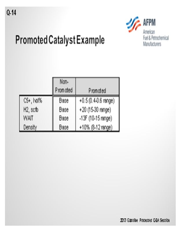
Promoted or multi-metallic reformer catalysts have been a topic of research since at least the early 1970s. They have been tried commercially in various forms over the years, all with the objective of improving yields by suppressing the demetallization reactions. The current promoted catalysts have advanced the formulation of manufacturing techniques to new levels of performance. Recently, Phillips 66 has selected promoted catalysts for future reloads in at least three of our sites. The additional cost of the catalyst is justified when considering increased product yield and improved activity that allows a lower reactor temperature requirement, which both provide for a very quick payback on the additional catalyst cost.
The example shown on the slide indicates the additional yields – both in the C5+, as well as hydrogen – and some improved activity that might be expected with a promoted catalyst. When selecting the promoted catalyst, regeneration procedures should be reviewed with the catalyst vendor to ensure that maximum catalyst performance from regeneration to regeneration is achieved, particularly in the area of reduction and dryout steps.
BULLEN (UOP LLC, A Honeywell Company)
We have two catalysts that we offer in the semi-regenerator market and also for cyclic reforming applications. One of them is the R-98 catalyst that was introduced in 2005 and which has over 50 installed applications. We have a new catalyst called R500 that has better activity and stability, and we have put it in 10 units. As Craig said, proper regeneration procedures are very important for any semi-regeneration unit, and maybe even more so for these tri-metallic systems, because of the issues related to dryout and reduction. It is important to get consistency with this procedure because you will lose the advantage of the tri-metallic system if you do not do the dryout and reduction correctly. Getting that repeatability is very important.
CRAIG MELDRUM (Phillips 66)
Regeneration procedures should be reviewed with the catalyst vendor to ensure maximum catalyst performance from regeneration to regeneration. For example, UOP R-72 was a promoted catalyst offered about 15 years ago and required a different reduction procedure than the non-promoted catalyst for hydrogen concentration, pressure, temperature, and dry-down schedule.
PATRICK BULLEN (UOP LLC, A Honeywell Company)
Trimetallic catalysts containing rhenium are typical for use in fixed-bed reforming applications, both semi-regenerative and cyclic reforming applications. In recent years, both additional metals and oxides have been added to platinum-rhenium reforming catalysts. Metal promoters have been added to increase selectivity and product yields. The additional metal partially suppresses platinum-rhenium activity, reducing metal-catalyzed hydrogenolysis that lowers selectivity.
Over the past decade, UOP successfully developed the proper catalyst base, formulations (including promoter type), and manufacturing techniques needed to generate catalysts that demonstrate excellent yield stability and regenerability. UOP’s R-98 catalyst was introduced in 2005 and has over 50 successful applications with many regeneration cycles, and our customers are benefiting from the higher yields. UOP recently introduced a new product, R-500, that shows even great activity and stability, with over 10 commercial applications. It is well suited for reforming units where even longer cycle lengths are desirable or where higher activity is needed to push more barrels. The gradual acceptance of promoted catalysts is analogous to that of the bimetallic catalysts having higher rhenium content that preceded them in this market.
Proper regeneration procedures are critical for the success of any semi-regeneration catalyst; and in particular, promoted formulations that have reduced metal activity. One Best Practice is to ensure proper dry-down, reduction, and sulfiding. Cyclic reforming applications are a little more demanding due to the regeneration environment (higher moisture and sulfur, for example), but new promoted formulations have been demonstrated in these applications as well.
SONI OYEKAN (Prafis Energy Solutions)
This question needs some more definition to elicit appropriate responses with respect to what is truly a “trimetallic” catalyst. My initial response is that my experiences in the use of “trimetallic” platinum-rhenium catalysts for fixed-bed cyclic regeneration reformer operations were good. The catalysts performed as projected by the catalyst and technology supplier for catalysts containing a third metal that was specifically added for modifying the acidic functionality of the catalysts.
Having written that, it is important to understand the type of catalysts commonly referred to as “trimetallic” catalysts. The term could cover Pt/Re (platinum/rhenium) catalysts with a third metal as a modifier for the alumina to moderate the acidic functionality of the catalysts or those in which the third metals are added to modify the hydrogenation functionality of the platinum or to moderate rhenium hydrocracking activity. In other trimetallic catalyst formulations, the third metal can work in conjunction with the rhenium as co-promoters for the platinum functionality.
The performance objective of the third metal is crucial in order to assess long-term performance and benefits of the third metal. Metals on catalytic reformer catalysts typically undergo varying degrees of reduction to different oxidation states at different temperatures and adequate metals redispersion are achieved at different oxidative conditions. Trimetallic catalysts’ expected performances and potential limitations should be well understood by oil refiners before acquiring them for use. Catalyst suppliers should provide test data to show multiple regenerations and adequate reactivations of the three metals, even if the other two metals are acting as co-promoters for the platinum. Another key factor is to ensure that optimal metals distributions are achieved during catalyst manufacture. There are other factors to consider that are beyond inclusion in this short response on trimetallic catalysts.
If the third metal has been added to moderate catalyst acidic functionality and reactivation of that third metal is not an important factor other than decoking, then the refiners’ challenges are lessened to some extent. It should be recalled, however, that the history of catalytic reforming is dotted with an oil refiner’s experiences with second metals that had been added to the platinum and which led to significant performance problems. The problems were related to inadequate metals activation, especially poor redispersion of the promoter metals, and these problems led to poor catalyst performance for subsequent cycles after the first cycle for fixed-bed catalytic reforming systems. Furthermore, in reforming catalyst development programs, the addition of metals to Pt/Re catalysts led to increased feed sulfur sensitivity challenges for the resultant trimetallic catalysts. Feed sulfur sensitivity and catalyst regeneration challenges should be studied sufficiently by the catalyst and technology supplier during that supplier’s catalyst development studies leading to the production of “trimetallic” catalysts.
Year
2013
Process
Question 15: What is the Best Practice process for sampling, handling, and measuring research octane (RONC) and naphthene content in reformer feed and product? Are refiners considering online RONC and/or other property monitoring?
MELDRUM (Phillips 66)
If you have a poor octane result, the Best Practice is to blame the lab. Isn’t that what we do? The reality is that there are at least four key components of a sample system that all need some attention: sample conditioning, container contamination, sample degradation between collection and analysis, and the analysis method. The Best Practice for sample conditioning uses a fast loop to keep a fresh representative sample of the process at the sample point and minimize emissions that come from open-purging methods. As it pertains to reformer units, the container is typically a glass bottle, and standard bottle washing and air drying is adequate for contamination control.
Sample degradation can occur through the autoxidation of gasoline to peroxides when exposed to UV (ultraviolet) light, which can lower the octane number. One study found that samples exposed to sunlight in clear bottles for five hours resulted in a half to a full number drop in the octane number. Samples collected in amber bottles did not show a significant change in he octane number. Air in the free space from a half-filled bottle will also degrade the octane, though not as much as sunlight. To avoid the octane loss in a reformate sample, it is recommended to use amber bottles filled 80% full, capped with a clean cork or stopper, and held out of direct sunlight. They should also be analyzed in a timely manner.
Octane analysis is based on knock engine methods. Some sites may use laboratory infrared analysis to calibrate to the knock engine results; and in some cases, an online analysis might be done with the reformer unit. That is a valid technology; but for Phillips 66, it is not widely employed. That also directs attention back to Question 12 on blending from my previous comments on online analysis.
STREIT (KBC Advanced Technologies, Inc.)
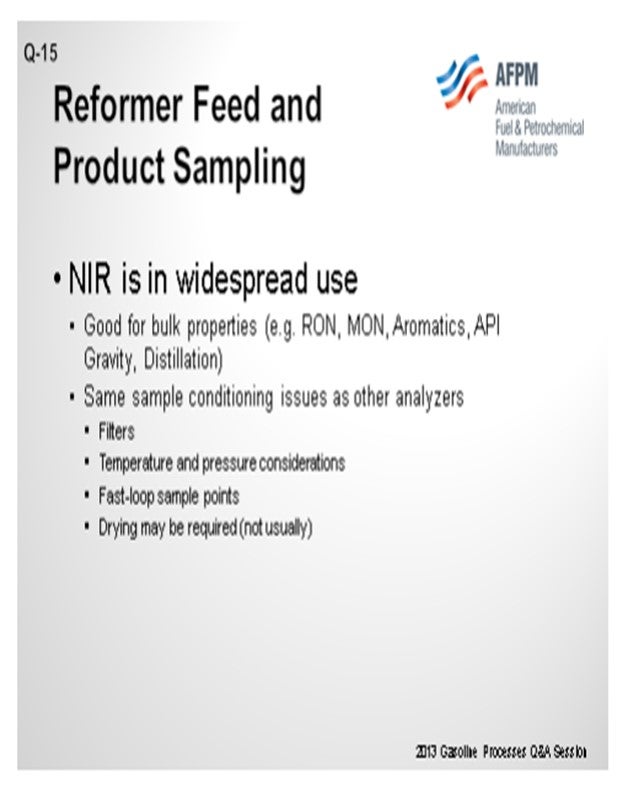
I want to point out that NIR analysis online for reformer feed and product is fairly widespread now. It is good for measuring bulk properties. It correlates well for RON (research octane number), MON (motor octane number), aromatics, naphthenes, gravity, and some distillation points. In those cases, the same sample conditioning is required for that analyzer as basically for any other. You need good filtration. You need to get a hot fast loop on the sample point and make sure that the temperature and pressure are reasonable at the sample point. You might need to dry the material, but this is not usually an issue with reformer feed or reformate.
BULLEN (UOP LLC, A Honeywell Company)
One additional comment about the Best Practice for sampling: If you are not able to get to the samples quickly, refrigerating them allows them to remain stable longer. We have used that technique as a Best Practice. Related to online analyzers, it is not unusual for UOP to design online analyzers for our customers for product stream. We typically recommend a guided wave NIR analyzer. We recognize there are other analyzers available in the market. The costliest portion in these NIR analyzer systems is the calibration, which can take quite a while for these multi-component streams. The feedback from our customers has been generally positive. Once the calibration is done, people rely on them.
JAMES BROWN (Applied Instrument Technologies)
I would like to say that the NIR analyzers for this type of application are probably one of the earliest successful applications of the technology. We have had units in this application since the early 1990s. Although they are relatively expensive to install, they have relatively long lives. We had units that were operating for over 10 years with essentially the same instrumentation, so the payback over the scope of the instrument life is fairly good. Unlike blending where we seem to always change targets and continually have to update calibration models, once the calibration model is established for one of these systems, they are fairly stable and do not really require much updating with time. It is actually one of the easier applications to use.
CURTIS NEIL (Intertek Pilot Plant Services)
Does the panel have any experience with DHA (detailed hydrocarbon analysis)? I know that DHA is starting to become more prevalent. How does it correlate to the knock engines? And if you see octane values that you trust out of that correlation, is there any added benefit to, say, doing a DHA instead of a knock engine test? So I am curious if anyone on the panel trusts the detailed hydrocarbon analysis. Since that is a GC (gas chromatography) method compared to the results that you get from the knock engine, is there any correlation there that you feel that gives you any added value to possibly do that instead of running a knock engine?
MELDRUM (Phillips 66)
The DHA analysis has proven effective and does not require much sample volume like that of a knock engine. Pilot operations tend to use a DHA, and we do find them to be acceptable.
STREIT (KBC Advanced Technologies, Inc.)
With a lot of the NIR analyzers, the analysis time is fairly fast. You can manifold up multiple sample points to the same analyzer. We are talking about the payback that you mentioned before. Another way to mitigate some of the costs of the system is to have it analyze multiple streams.
CRAIG MELDRUM (Phillips 66)
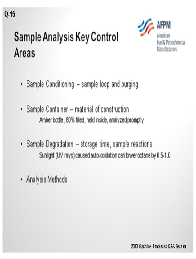
Accurate sample analysis involves attention to four key areas:
• sample conditioning (such as purging of the sample station),
• container contamination,
• sample degradation (storage time, storage conditions, reaction with sample container material), and
• analysis methods.
Best Practices for sample conditioning involve fast loops to keep a fresh, representative sample at the sample point and to minimize emissions compared to open purging.
Container contamination is adequately handled with bottle washing and air drying.
Reformate sample degradation can occur.
• Auto-oxidation of gasoline to peroxides through exposure to sunlight (UV rays) will lower the sample octane number. One study found that samples exposed to sunlight in clear bottles for five hours resulted in 0.5 to 1.0 lower octane numbers. Samples in amber bottles did not see significant change in octane.
• Air in the free space from a half-filled bottle will degrade the octane, though not as much as sunlight.
• To avoid octane loss in a reformate sample, it is recommended to use amber bottles filled about 80%, closed with a cap with a clean cork or stopper. The bottles are held out of direct sunlight and analyzed in a timely manner.
• Antioxidant additives are only marginally effective in limiting peroxide formation through sunlight exposure.
Octane analysis is based on knock engine methods. Some sites may use IR analyzers calibrated to the knock engine results. Use of online GC analyzers for reformate octane is a valid technology, but one that is not widely used. See previous comments on Question 12 for blending.
PATRICK BULLEN (UOP LLC, A Honeywell Company)
A Best Practice for reformate sampling is to refrigerate the sample in a brown bottle to minimize the interactions of the chemical species in the sample.
It is not uncommon for refiners to request an online octane analyzer specification with a new CCR Platforming™ Process unit design. UOP recommends the Guided Wave NIR (near infrared spectroscopy) analyzer for product samples. There are other NIR analyzers available on the market. The costly portion of the NIR analyzer system is the time and labor to calibrate the analyzer for a given stream. Once they are calibrated, the customer feedback on performance has been positive.
ERIC STREIT (KBC Advanced Technologies, Inc.)
Near infrared spectroscopy (NIR) is in reasonably common operation use for analysis of gasoline for RON, MON, gravity, distillation, aromatics, and benzene. The analyzer is calibrated versus known standards for most properties. Octane analyses are calibrated against octane engine results. Repeatability for these analyzers is generally good. Because NIR can be used for a number of properties, it is normally the analyzer of choice.
Sample conditioning issues for NIR analyzers are the same as for any online analyzer (filter, temperature and pressure considerations, fast-loop sample point, etc.). Drying may be required, but this is not normally an issue for gasoline.
Year
2013
Process
Keynote
AFPM is pleased to announce that the Deputy Director for the Cybersecurity and Infrastructure Security Agency (CISA), Nitin Natarajan, will be the keynote speaker at the 2024 Security Conference. Director Natarajan is no stranger to the petrochemical and refining industry, having spoken at the 2023 AFPM International Petrochemical Conference and the AFPM sponsored Sam Houston University Institute of Homeland Security Thought Leaders Conference. In this keynote session Director Natarajan will discuss the role government and public-private partnerships will play defending against unconventional and new cyber attacks upon critical infrastructure.
Speakers
Session Start End
-
USCG Session: Cyber, Drones, and the Future TWIC Reader
Hear the latest on the TWIC Reader rule, future USCG cyber actions, and other MTSA issues.
Session Start End
-
Artificial Intelligence (AI) Security Issues: Pros & Cons
This session will review the potential security risks and security benefits of AI in the petchem and ONG industry.
Session Start End
-
Domestic Violent Extremists (DMVEs): Targeting Critical Infrastructure
Domestic violent extremists have increasingly targeted critical infrastructure. This session will review past incidents and discuss this evolving threat.
Session Start End
-

Cybersecurity Session: Regulations, Policies, and What is on the Horizon
Cybersecurity threats continue to the ONG and petchem industry and the government has countered these threats with new regulations, policies, and voluntary programs. Hear the latest on this new evolving regulatory landscape
Session Start End
-