
Blake Berend
Question 31: With heavy gas oil hydrotreating and mild hydrocracking units producing diesel product with 30 to 50 ppm sulfur, what options do you employ to recover maximum volume of ULSD? Are there other diesel quality concerns, and how are they resolved? How does the yield and quality change over the cycle?
PATRICK GRIPKA (Criterion Catalysts & Technologies)
We have many customer examples of FCCPT units and mild hydrocracking (MHC) units directly producing on-spec ULSD with Criterion catalyst systems. Many refiners who are making 30 to 50 ppm sulfur diesel from hydrotreating and/or mild hydrocracking unitsare able to blend this into the diesel pool and still have the whole pool meet the less than 15 ppm diesel sulfur specification. In these cases, there is typically overtreating in another hydroprocessing unit.
Assuming unit pressure and recycle gas, rates are maximized, in order to reduce the sulfur to the ULSD level, the immediate options a refinery has are feed rate, feed composition, and feed cutpoint. All are essentially managing the overall feed difficulty and processing requirement in the hydrotreater. Depending on refinery flexibility, it may be feasible to move a portion of the most difficult feed stream to another hydrotreating unit so the subsequent easier feed will produce a lower sulfur diesel. Another solution is to lower the feed endpoint and send the hardest to treat molecules to another hydroprocessing unit. However, these options are less than ideal as there are often economic penalties due to non-optimal operation across these multiple units. The Best Practice is to improve the catalyst technology in the heavy gas oil hydrotreater or mild hydrocracker and produce ULSD directly.
I have two examples that demonstrate how catalyst technology has been used to increase overall ULSD make within an FCCPT unit. In both examples, the refiner chose the option of reducing feed cutpoint in previous cycles to meet the desired diesel properties so on-spec ULSD was being produced. However, use of improved catalyst technology has allowed the cutpoint to be increased in subsequent cycles.
Example 1: Potential to Significantly Increase the Endpoint and Increase the Amount of ULSD Make
The graph below shows product sulfur level and the endpoint of the diesel product from an FCCPT unit. Two cycles from an FCCPT unit are represented, and the catalyst was upgraded to a CENTERA™ catalyst system in Cycle 2. Both cycles were consistently producing diesel in the 1-to 30 ppm range; however, the big difference is that the diesel T90 in Cycle 1 was limited to the 525 to 575°F range, which is a very light diesel (almost a kerosene), but the diesel T90 in Cycle 2 is in the 625 to 670°F range, which represents a 100°F increase in diesel T90. Feed qualities and operating conditions are similar between the two cycles. The improved catalyst performance has resulted in an overall increase in recoverable diesel. As noted above, one of the biggest levers to maximize cutpoint is proper catalyst selection.

Example 2: Potential to Continue Producing Higher Amounts of ULSD as the Cycle Progresses
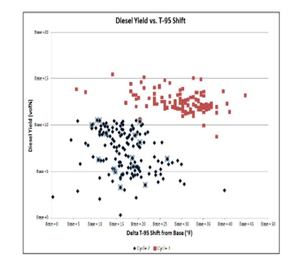
The graph below shows percent diesel yield versus days onstream; the red dots represent the previous cycle; and the blue dots represent the subsequent cycle with an improved catalyst system. Here the FCCPT unit processes all the coker gas oil –heavy and light –in the refinery. The yield of ULSD removed in the fractionator is very important to the economics of the refinery. The improved CENTERA™ catalyst system resulted in a more stable ULSD yield profile as the previous cycles exhibited a drop-offin ULSD production at the end of the cycle due to the unit’s inability to maintain product sulfur at the higher endpoint. Over the cycle with the improved CENTERA™ catalyst system, the average yield of diesel was 5% higher, with an average 10°F higher diesel fraction T-95compared to the previous cycle.

In terms of diesel quality, the diesel produced from the FCCPT or MHC unit routinely meets U.S. specs. As shown below, the diesel cetane for this unit meets/exceeds U.S. specifications and was similar for both cycles and exhibited stable quality over the cycle.

DAVID VANNAUKER (Haldor Topsoe, Inc.)
Diesel sulfur has a profile with the sulfur concentration increasing as the boiling point increases. A simple option is to produce a wider-cut jet stream that can be used as a blend stock with ULSD. Another option is to change the next catalyst load to increase the HDS functionality, which has been proven to enable the full wide-cut ULSD. When units increase the EP, there is a potential for higher pour/cloud point. Employing dewaxing or isomerization catalysts can resolve this issue.
Question 32: What are your current practices and experiences of performing online cleaning of heat exchangers versus offline cleaning?
SAM LORDO (Nalco Champion)
To achieve a good online cleaning (with the exchanger bypassed by not pulled), it is imperative to have nozzles on the inlet and outlets that are large enough to facilitate the circulation of a heat cleaning solution or steam with a cleaner. Recovery of heat duty is depended on the velocity of the cleaner, the foulant material, and whether the cleaning solution actually came in contact with the foulant (100% fouled-off exchangers are hard to clean online). Typically, online cleaning can be used successful and recover 60 to 80% of the flow or duty. Offline cleaning is more thorough, if done properly and recovery is routinely higher.
RON PARISE (Nalco Champion)
We have seen good success through the continuous application of one of our cleaning chemicals at low dosages with some online exchangers, particularly B/E (bottom entry) exchangers in desalters. For offline cleaning, it is critical to have sufficiently sized injection nozzles/circulation nozzles (at least 2” diameter) to afford enough turbulence with the cleaning solution to provided effective cleaning of the exchanger.
Question 33: Can you share your experience with chemical additives to prevent fouling in the naphtha hydrotreater feed side of the feed/effluent heat exchangers or resolve reactor pressure drop issues?
CHRIS CLAESEN (Nalco Champion)
The answer is partially the same as the one given to Question 28. First, the root cause needs to be determined. If the dP is caused by corrosion products due to corrosion in the upstream refinery units, the corrosion in these units can be reduced by applying the proper corrosion control program. If the dP is caused by gum formation, the gum formation needs to be controlled by applying a program in the feed and storage system. While we recommend that the focus be on prevention measures, we have successfully reduced hydrotreater dP on many units by applying an online cleaning program.
DENNIS HAYNES (Nalco Champion)
A hydrotreater processing import naphtha was experiencing reactor bed pressure drop well into the run. It was suspected that particulate iron sulfide was a main component of the material restricting the upper portion of the reactor. It was not possible to stop the pressure drop increase in this case, but application of a dispersant resulted in a reduction in the rate of pressure drop increase to the extent that the unit could make it to turnaround. For chemical additives, it is important that due diligence is done in the evaluation of the fouling mechanisms so that the appropriate inhibitors can be fit for purpose.
WALTER MILITELLO, PhD (Nalco Champion)
Several units have shown some degree of fouling, usually impacting the heat transfer performance of heat exchangers and producing hydraulic restrictions at HT reactors. Fouling nature can be organic or inorganic, depending on feed contaminants and operating conditions. The most successful approach to minimize pressure drop buildup is the application of top reactor dispersant agents. The function of those agents is to disperse the foulant material, thereby reducing its adhesivity and compacting. Often those agents are able to break fouling crust, if injected properly and at the correct dosage and duration. If it is not possible to implement the dosing system during the plant operations, an alternative solution is the injection of dispersants from the preheat train. The immediate benefit is to recover heat transfer across feed/effluent exchangers; because usually, the fouling problem also impacts the cross-exchangers. But careful dosing strategy and accurate monitoring must be in place to avoid significant fouling material transportation from heat train to reactor, making the hydraulic situation worse. Recent experience of dispersant around a Saudi plant, showed a FF (fouling factor) reduction of cross-exchangers from 0.007 ft2hr°F/BTU growth every month, to a growth rate of less than 0.001 ft2hr°F/BTU per month. The reactor norm-dP(flow corrected) growth during the chemical program was only 0.12 psig per day, compared to previous cycle where norm-dP grew at a rate of 0.22 psig per day, resulting in a premature cat skimming after 11 months from fresh cat startup.
RALPH WAGNER (Dorf Ketal Chemicals LLC)
The fouling precursor can be classified into two groups: organic and inorganic. Organic precursors are due to the presence of unsaturated in cracked feedstock which forms polymers and coke, depending on the operating conditions. Inorganic precursors are due to the presence of a corrosion product coming from the unit upstream. Both precursors agglomerate and deposit on the preheat exchanger surface; and at a break-even point, they get carried to the reactor, further aggravating the fouling scenario. Dorf Ketal offers a range of antifoulant chemistries specific to the precursor type. Typically, an antioxidant is used to terminate the polymer formation, while dispersant chemistry uses steric barrier to limit the particle size and deposition. Dorf Ketal has successfully treated naphtha hydrotreaters worldwide for organic and inorganic fouling. Dorf Ketal’s FeS agglomerate has been proven successful for inorganic fouling and has resulted in run-lengths being increased by several months with sustained pressure drop.
Question 34: The cycle life of a high-pressure ULSD unit operating for maximum aromatic saturation and liquid yield is limited by aromatics equilibrium at elevated temperatures. What strategies or solutions do you employ to extend operation with maximum liquid yield?
PATRICK GRIPKA (Criterion Catalysts & Technologies)
Methods to reduce aromatics levels in ULSD product streams were discussed in detail in Question 52 at the 2015 AFPM Q&A. The key factors to maximize aromatic saturation highlighted were:
*Maximization of hydrogen partial pressure (H2 pp),
*Utilization of full catalyst activity,
*Optimization of bed temperature profiles,Selection of highest hydrogenation catalysts, and
*Application of Enhanced Aromatic Saturation options.
This question is more related to EOR conditions when you have employed all of the operational techniques but wish to further optimize the EOR performance without yield decline. If you are already maximizing H2 pp (partial pressure), achieving full catalyst utilization with state-of-the art reactor internals, and adjusting bed profiles at MOR/EOR (middle-of-run/end-of-run) to remain in region of optimum aromatic saturation, the following example illustrates the benefits of optimizing the nickel-molybdenum catalyst for your application.
In this example, a high-pressure (HP) ULSD unit which processes mostly cracked stock (primarily very high endpoint LCO) was using a high activity NiMo ULSD catalyst. This unit was initially commissioned in 2006; and over the years, it has experienced a significant increase in feed rate and difficulty of the cracked stocks processed. The increased severity was balanced with advances in Criterion’s catalyst technology to maintain arobust cycle life.
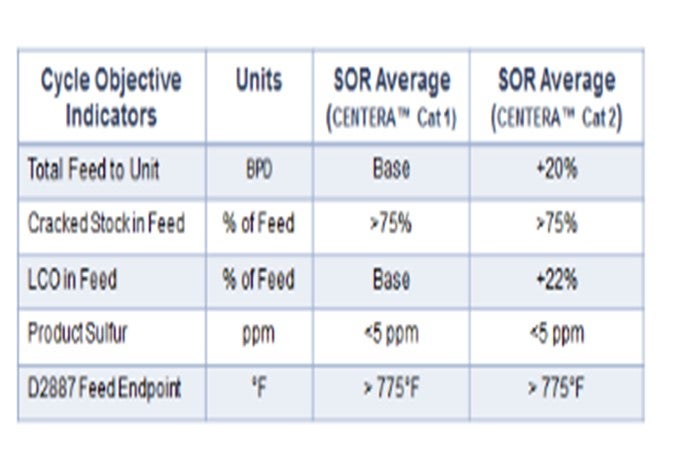
Last cycle, the customer used Criterion’s high activity NiMo CENTERA™ ULSD catalyst (Cat 1 in the figure below), but additional aromatics saturation was desired for anticipated feed quality changes to further maximize volume gain again next cycle. The challenge of processing 20% more feed containing 22% higher LCO of increased endpoint required improved feed and product diffusion to facilitate increased hydrogen addition. Under the new conditions, a different Criterion CENTERA™ NiMo catalyst (Cat 2 in the table below), having a wider pore carrier technology, was employed in the current cycle with additional improvement in performance realized.
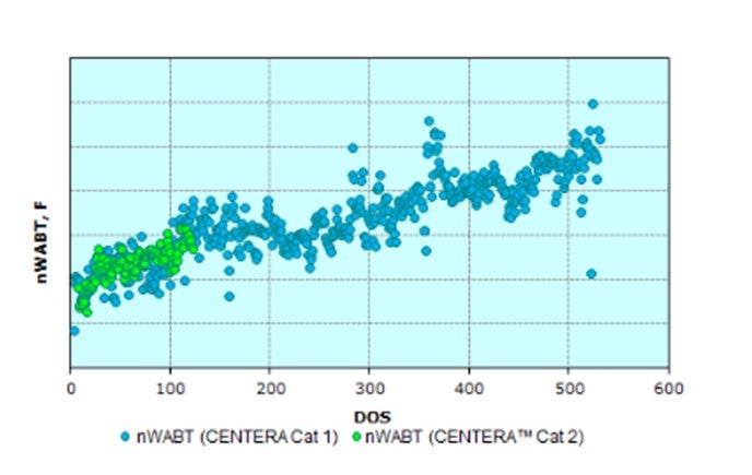
The overall normalized WABT performance has been similar, but the table below shows that asignificantly higher amount of very heavy LCO was processed; in addition, the overall feed rate was increased by another 20% compared to the previous cycle. This difference highlights the significant improvements in performance and yield maximization gained by using catalysts designed to process feeds with a higher than typical endpoint in ULSD; and ultimately, maximize the yield of ULSD.
In addition, the catalyst system exhibited increased aromatic saturation capability, and the unit exhibited maximum volume gain by utilizing all makeup hydrogen available to the unit.
The incorporation of mild hydrocracking functionality into a catalyst system can provide additional improvement at EOR. Of course, one could reduce T-95 EP of the most difficult feed stream(s), but this will result in a reduction in overall distillate yield. In order to maintain liquid yields at higher temperature conditions which are present as the cycle gets near EOR, the appropriate use of mild hydrocracking catalysts in the catalyst system will allow the conversion of the higher boiling molecules while still meeting product specifications.
Utilization of a mild hydrocracking (MHC) mode of operation will first have to be evaluated for equipment and unit compatibility. Question 18 in the2011 Q&A specifically dealt, in detail, with the considerations needed to include MHC catalysts in a ULSD unit. The key considerations are:
*Safety: The unit must have a sufficient number of beds with sufficient quench to handle any potential exotherms from incorporation of MHC catalysts into the catalyst system. Depressuring systems may also be required.
*Sufficient H2Supply: The unit must have sufficient H2supply to accommodate the additional H2consumption when operating in MHC mode.
*Product Separation Capacity: It must be verified that the ULSD unit product separation system is able to manage the additional naphtha production that will result.
Once concluding these considerations have been met, then inclusion of MHC catalysts can be beneficial. One example is a ULSD unit in which the operatortook advantage of advances in catalyst activity improvements by incorporating MHC catalysts in the upgrading zone to process heavier feeds and increase the overall diesel yield. The customer challenged us to provide more T-95shift to allow them to upgrade heavier feeds while still maintaining overall diesel yield.
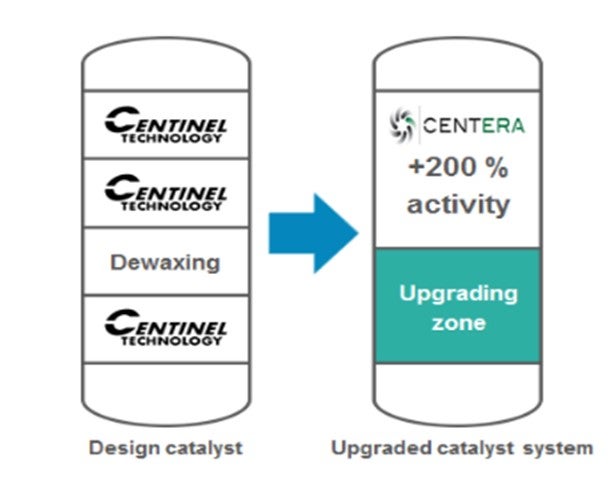
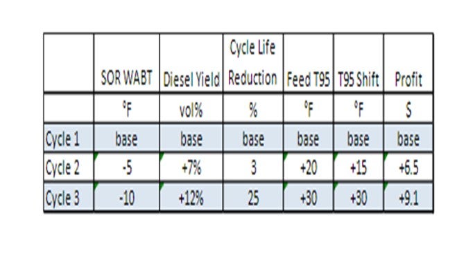
With the base T-95shift as the design catalyst cycle, the upgraded catalyst cycle in two subsequent cycles has shown the ability to process a significantly heavier T-95feed (about a 15°F increase in T-95shift in Cycle 2). With further improvements to the catalyst system employed in the Cycle 3, an even heavier feed has been processed (about a 30°F increase in T-95shift compared to the original cycle). After the first cycle, the customer challenged us to provide even more T-95shift to allow them to upgrade heavier feeds.
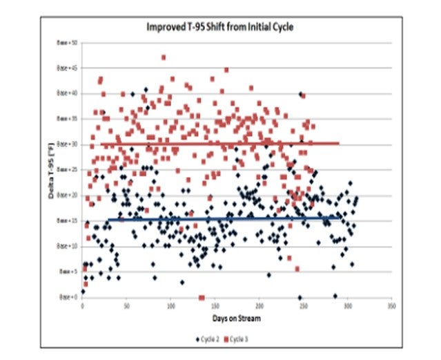
The greater T-95shift has also allowed the diesel yield to be not only be maintained but actually increased from cycle to cycle.
Overall, the T-95has been increased by about 30°F, and diesel yield has increased about 12 vol% compared to the base cycle. This improvement was achieved by optimizing the catalyst configuration and taking advantage of the combination of excellent pretreat hydrogenation power and the desired hydrocracking selectivity.
This higher diesel yields and processing heavier feedstocks has resulted in increased unit profitability of $6.5 to 9.1 million per year, as summarized below.
Incorporation of MHC catalysts into a ULSD unit can provide significant additional diesel yield due to endpoint conversion. The enhanced functionality and stability of MHC catalysts allows them to extend performance beyond the thermodynamic equilibrium limitations which impact conventional hydrotreating catalysts at EOR. In conclusion, there are strategies to maximize ULSD liquid yield by utilizing the optimum catalyst for the desired objectives; and where unit capabilities allow, incorporate MHC catalysts into the unit.
SERGIO A. ROBLEDO (Haldor Topsoe, Inc.)
The strategies for extending the operation of a high-pressure ULSD unit, with maximum yield, depends on a number of factors. The hydrogen partial pressure, LHSV, and hydrogen availability along with the layout of the unit are key factors. Catalyst design and type are also key to maximizing yield. Improving aromatic saturation, specifically monoaromatic saturation, is a driving factor for maximizing yield. Generally speaking, NiMo catalysts will improve the amount of monoaromatic saturation over CoMo catalysts; however, this is dependent on both hydrogen partial pressure and feed nitrogen content. The potential level of aromatic saturation will also depend on the LHS V of the unit.
Therefore, a NiMo catalyst with unmatched hydrogenation activity, much like Haldor Topsoe’sTK-611HyBRIM™ catalyst, is the first strategy for extending operation above a certain yield level. TK-611HyBRIM™ will provide approximately an additional 0.5% increase in liquid yield over top -tier catalystTK-609HyBRIM™. This additional 0.5% yield on a 40,000 bpd unit is an additional 200 bpd on top of the existing volume swell. This incremental swell alone is worth about $3 million per year and will easily pay for the entire catalyst load in three to six months. Depending on the reactor system design, the possibility of raising the front-end temperatures higher to accomplish the HDS reactions, while lowering the reactor outlet temperature to maximize aromatic saturation is a viable strategy. This operation can be accomplished by raising furnace outlet temperature to raise reactor inlet, while removing inter-bed quenches. The quench to the final bed should be maximized to lower reactor outlet temperature to the peak aromatic saturation temperature. Haldor Topsoe also offers their ULSD Polyshift™ and FCC Aeroshift™ technologies to maximize aromatic saturation and, in turn, volume swell. Please contact your Haldor Topsoe representative for more information on these technologies.
Question 35: What are possible causes do you see of high product nitrogen in a naphtha hydrotreater processing coker naphtha? Please include monitoring, identification, and troubleshooting techniques, inside and outside battery limit considerations, and mitigation options.
SERGIO A. ROBLEDO (Haldor Topsoe, Inc.)
There are a number of possible causes of high product nitrogen in a naphtha hydrotreater. The list below details some of the most common.
1.Higher and/ or more difficult feed nitrogen,
2.Hidden tails not caught by ASTMD-86 method,
3.Lower outlet hydrogen partial pressure (as a result of lower hydrogen purity and /or lower hydrogen makeup/ recyclerate
4.Poor or incorrect lab analysis,
5.Amine injection downstream of the reactor for corrosion control,
6.Co-mixing of high-nitrogen product from another unit upstream of the sample point, and /or
7.Silicon poisoning of catalyst (i.e., either unexpected slugs or unknown).
Daily monitoring of feed nitrogen and distillation, via the Sim Dist (simulated distillation) method, will allow the refiner to adjust reactor temperature or control the final boiling point to meet the desired product nitrogen. Daily monitoring of product nitrogen is also key to establishing the percent of HDN (hydro denitrification) removal across the reactor system. Monitoring the treat gas hydrogen purity on a daily basis, and maintaining the right amount of hydrogenrate, are also key to ensuring that there is proper hydrogen partial pressure in the system to meet the expected level of nitrogen removal.
There have been a number of instances where poor lab analysis was responsible for a perceived under performance of a catalyst system. In a particular unit, start -of- run %HDN levels were the highest they had ever been – greater than 90% –after the installation of Haldor Topsoe’s highly succesful BRIM® catalyst. After a few months at this level, the % HDN suddenly dropped to the range of 30 to 50%, while the % HDS remained quite high. Even though the % HDS was still at or above 90%, silicon poisoning was suspected, as silicon impacts the HDN activity to a greater extent. However, the % HDN suddenly recovered top revious levels above 90%, which would not have occured if silicon poisoining had taken place. The lower % HDN turned out to be an analytical issue.
It is also always important to be aware of which streams are being injected into the product of the naphtha hydrotreater as they could artificially raise the product nitrogen.
ARTURO CONTI (Criterion Catalysts & Technologies)
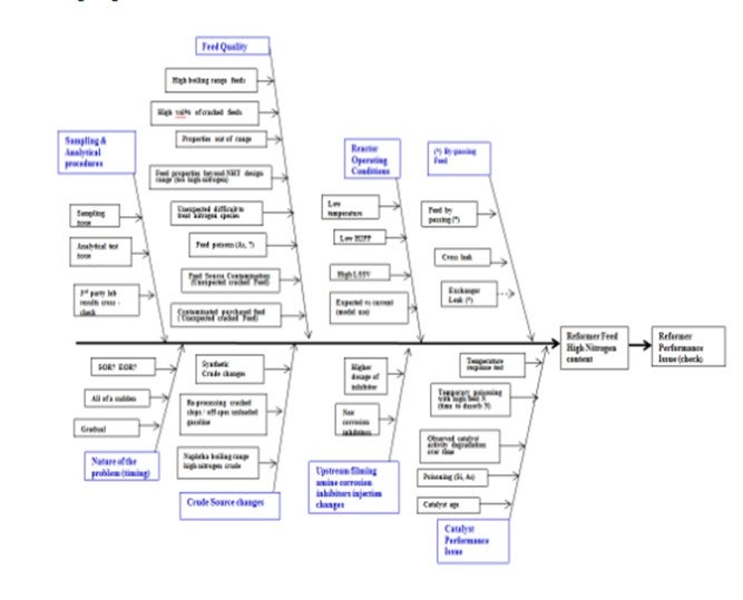
High product nitrogen from a naphtha hydrotreater (NHT) processing some coker naphtha and providing feed to a catalytic reformer is of concern since nitrogen affects the performance of high value reforming catalyst. The naphtha hydrotreater product specifications are typically less than 0.5 ppm sulfur and nitrogen in the feed to the reformer. When higher product nitrogen is measured, it is critical to identify and correct the issue as quickly as possible. When product nitrogen is high, there are many possible causes. The fishbone diagram below describes many of these causes that need to be reviewed in order to narrow down the potential reasons. Coker naphtha specifically lowers the feed quality with cracked components and brings higher level of contaminants.
In a recent customer troubleshooting effort, the product naphtha from a NHT went off-test at same time as some new feeds were being processed in the refinery. Samples were analyzed at the refinery lab and various outside labs, as well as at our Shell Technology Center labs. It was surprising how variable the results were for the same samples. Results varied from 0.3 ppm to 2.5 to 3 ppm for each of the samples. The refinery analyses were in the middle, and the Shell Technology Center results indicated that all the samples were on-spec at less than 0.5 ppm.
After reviewing the possible causes and not identifying anything to explain the results, we recognized two other key pieces of information:
1.The other NHT unit processing SR feeds was also off-test, as was the naphtha from the ULSD unit, and
2.The reformer was not showing any signs of high feed nitrogen.
After reanalyzing samples to confirm the low product nitrogen, it was decided that analytical lab error was the likely cause, and the product nitrogen actually was within specification. Although it could have been any of the potential items which led to a high nitrogen product, analytical error was the issue here.
Question 36: Which refinery water sources do you accept for hydrotreater water wash (e.g., stripped fractionator overhead water, stripper sour water, etc.)? What are typical water quality guidelines?
JEFFREY MUELLER (Marathon Petroleum Company)
Waterwash systems must be designed well, with good water contact and draining, or the wash can create significant corrosion concerns, potentially resulting in process safety incidents. MPC experienced this first-hand with an intermittent wash system on an NHT unit. Though there were many issues identified as causal factors during this incident, the design of the waterwash system played a part in the failure.
On April 9, 2015, a failure occurred on the top of a horizontal section of reactor effluent piping of a naphtha hydrotreater. The escaping stream of hydrocarbon was estimated to be 70 to 80feet high, and the sound of liquid hydrocarbon release made communications in the immediate area difficult. Fortunately, the unit operators were able to shut down the heaters without incident. Figure 1 illustrates the piping failure associated with this incident.
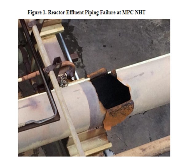
The piece of piping that failed was located directly downstream of the feed/effluent exchangers and a continuous waterwash injection point, upstream of the reactor effluent air coolers. The systemoperated at 320 psig and 280°F, with no prior history of leaks. The process, at this point, contained 0.2 mol% H2S, 0.001 mol% NH3, and 0 to 4 ppm chloride in the makeup hydrogen. These conditions are not severe by hydrotreater standards.
The failure was internal corrosion due to the condensation of HCl on the vapor space of the pipe. Some of the causal factors in this incident relate to the waterwash design (though this was not the exclusive cause). The presence of water with inadequate mixing created an extremely corrosive condition in the vapor space of the horizontal pipe. A couple physical factors related to the waterwash contributed to this inadequate mixing:
*The water was injected through low velocity quills.
*Water was injected upstream of a non-freedraining low point with long horizontal line.
*Typically, waterwash is injected immediately upstream of the REACs. In this case, there was a long horizontal run of piping immediately downstream of the injection that does not allow for adequate mixing.
CHRIS STEVES (Norton Engineering)
Refiners typically use stripped sour water or boiler feedwater as hydrotreater washwater. While stripped sour water is usually cheaper and of adequate quality for hydrotreater washwater, it may not be available at high enoughpressure for use as hydrotreater washwater, and BFW (boiler feed water) may be available at the desired pressure from existing equipment.
Question 37: What is the impact of CO (carbon monoxide) and/or CO2 (carbon dioxide) on noble metal catalyst performance?
AMIT KELKAR (Criterion Catalysts & Technologies)
CO and CO2are poisons for noble metal catalysts, with CO being a very strong poison. Contamination level as low as 50 to 100 ppm can result in significant and permanent loss of activity. CO should be limited to less than 10 ppm. In our experience, units which achieve long cycles (10 years plus) typically have CO levels less than 5 ppm.
RASMUS EGEBERG (Haldor Topsoe A/S)
It is known that CO can inhibit noble-metal active sites by competitive coordination, there by effectively preventing hydro carbons from adsorbing and reacting in aromatic saturation or isomerization reactions, for example. CO and/ or CO2 can be introduced as impurities in the treat gas or, in some cases, when using natural gas as stripper gas. The effect is temporary and disappears when the impurities are removed from the feed. CO2 is relatively inert and only has a minor effect on reactions; but in the presence of hydrogen, the CO2 will be partially converted to CO in a water /gas shift reaction (Eq.1).
Eq.1: CO2 + H2 ⇄ CO + H2O
It is also well known that transition metals, like Pd (palladium) or Pt (platinum), can facilitate the reduction of carbon monoxide into methane and water Eq.2: Methanation).
Eq. 2: CO + 3H2 ⇄ CH4 + H2O
The methanation reaction can provide an “outlet” for the CO that would otherwise inhibit the intended reactions. Methane and water do not inhibit reactions. The extent of these reactions and the surface coverage of CO depend critically on the catalyst activity and the process conditions, which means that the degree of CO inhibition is a function of these parameters. In particular, the reaction temperature has a high impact on both the adsorption strength and on the methanation rate constant. Haldor Topsoe has performed pilot plant tests that illustrate this calculation. In one test, the addition of 100 ppmv (parts per million by volume) CO to the treat gas resulted in a hydro dearomatization activity only one-third of that when using pure hydrogen as treat gas. In another test done at higher temperature, the effect of up to140 ppmv CO was negligible and a diesel product with less than 0.5wt% total aromatic content could be produced. In this case, complete conversion of CO to methane was observed. The process conditions that enable high noble metal catalyst activity to depend on catalyst composition and feedstock. HaldorTopsoe has a wide portfolio of noble metal catalysts and extensive process design experience that enable optimal performance, even in cases where impurities such as CO make life hard for the catalysts.
Question 38: What do you see for the future of ebullated bed technology considering changes in crude quality and availability?
DAVID McNAMARA (Criterion Catalysts & Technologies)
With the worldwide requirement for higher conversion of residue into lighter, more valuable transportation fuels such as diesel remaining firmly in place, we very much see ebullated-bed (EB) residue hydrocracking building on its current trend as a bottom-of-the-barrel upgrading technology of choice going forward. Investment in this commercially proven, well-established technology is a way to increase complexity and ensure long-term survival in an increasingly volatile marketplace.
Ebullated-bed residue hydro cracking is a Bottom of the Barrel Upgrading technology spanning 16 operating units commissioned over six decades since the first commercial unit came onstream in 1968. The early generation EB resid units were designed to process 100% vacuum resid (VR) feeds from a fixed crude slate targeting high removal of contaminant metals, CCR, and sulfur. With the push for higher bottoms conversion emerging in the 1990s, the key operational objective shifted to maintain an economical onstream factor by ensuring that the associated higher fouling rates leading to cycle-limiting higher sediment formation were adequately controlled.
With the dawn of the opportunity crudes era, the trend has been to use these units more as the key component in driving refinery crude diversification economics. Accordingly, more and more of the existing operating EB resid units are moving away from processing their design crude slate. Simultaneously, grassroots units are incorporating additional innovative designs (including interstage stripping, optimized hydrogen management, and integration in the same high-pressure loop with hydrotreating and hydrocracking units) to handle more variability in crude diet.
Investing in an EB resid unit not only brings with it the Best Practices learned from the very long operational history and proven upgrades, but also the opportunity to use the catalyst as a dedicated process variable in itself. Working in tandem with hydrogen partial pressure and the use of aromatic diluents such as slurry oil, the EB resid catalyst is the first line of defense that can be most readily applied. When there is a frequent change in crude slate, the catalyst addition rate can be varied as required. In addition, EB resid sediment control catalyst development in Criterion is based on a customized 4Cs approach wherein the Catalyst development, the Chemistry of the upgrading process is fully delineated; the Composition of the varying feed is very well characterized; and reaction and workup section Conditions, including unit limitations and key fouling locations, are closely monitored.
There is no doubt that processing vacuum residue(VR) feeds from a variable crude diet does present greater operational challenges for maintaining economical onstream factors in ebullated bed residue hydrocracking units. However, with proper management of crude changes, effective unit monitoring and application of Best Practices, such an operation, can also be a keyprofit-generating opportunity.