Question 62: What are causes of foaming in crude pre-flash drums and towers, and what options are available to mitigate foaming?
SHELTON (KBC Advanced Technologies, Inc.)
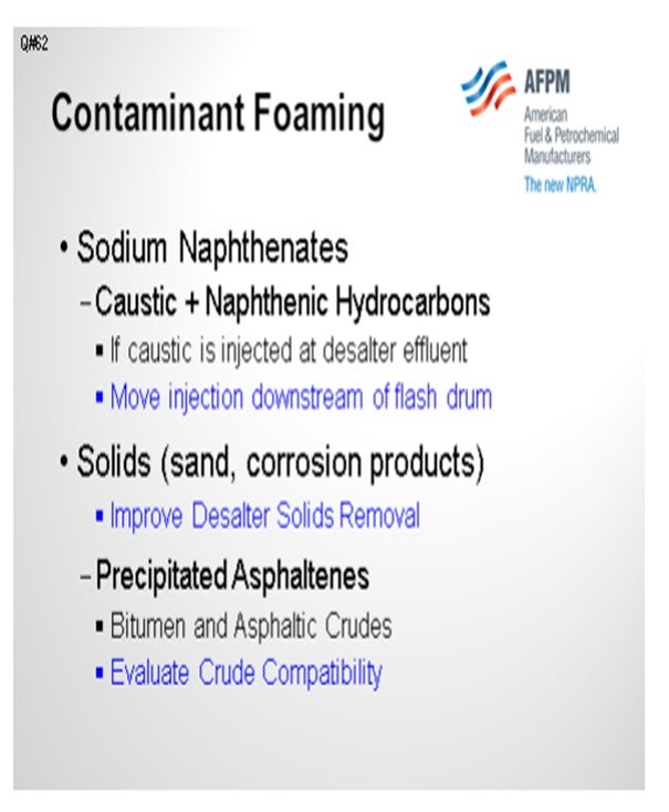
Surfactants cause foaming. Mike will discuss surfactants and amines that should not be in the crude. Sodium naphthenate is a common surfactant produced by the reaction of caustic injected at the desalter effluent and naphthenic hydrocarbons.
A simple solution is to move the injection downstream of the pre-flash or pre-fractionator to the bottom pumps. If the injection point is at the desalter effluent, solids and corrosion products can cause foaming.
Improving desalter solids removal will mitigate foaming. Precipitated asphaltenes that frequently occur with bitumens and asphaltic crudes can also cause foaming, so we would evaluate crude compatibility in that case.
The question includes pre-flash drums and towers, which I assume is a pre-fractionator. These applications are quite different in design and operation. In our pre-fractionator designs, we consider C factors, internals, tray design, and tower loadings.
We have used pre-flash drums in our latest grassroots designs because the hot trains have been so efficient that crude heater inlet temperatures are 600ºF to 610ºF. A flash drum removes water and requires lower pressure to suppress vaporization at the end of the hot train. The flash drum design avoids elevated pressures in the hot train and 900-pound flanges. Obviously, we specify vertical versus horizontal. We consider height versus diameter and liquid superficial velocity versus vapor velocity to optimize the ratio. We also consider disengaging height and the feed distributor inlet design. Of course, temperature and pressure have a major impact.

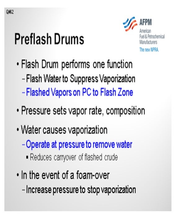
The pre-flash drum performs two functions: flashing water and suppressing vaporization. Many pre-flash drums are operated to remove light hydrocarbons. However, water causes vaporization, and operating pressure and temperature determine the vapor rate and composition. It is important to model the optimum pressure. Operate at the pressure required to remove water and not generate excessive hydrocarbon vapor load, which can result in carryover of bottoms.
In our designs, flashed vapors are sent to the flash zone. Designs where the flashed vapors are introduced in higher sections of the column can create problems. For any design, in the event of a foamover, temporarily increase pressure. With the flash drum, increase pressure until there is no vaporization. That will stop the foamover. It is important to have a pressure controller on that vapor line to the flash drum.
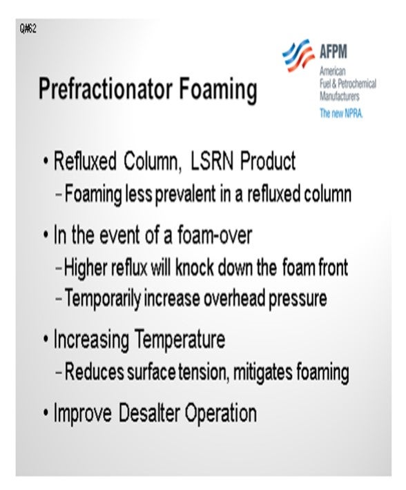
Pre-fractionator foaming is less likely because it is a refluxed column with an overhead product. The trays mitigate foaming, and the liquid loading should tend to knock down the foam. Again, in the event of a foamover, you could temporarily increase pressure. This may not be obvious, but we try to design for higher temperatures to reduce surface tension, which also mitigates foaming. In a new design, the pre-flash drum operating temperature is determined by the location in the hot train. Finally, improving desalter operation will mitigate foaming in the downstream columns.
BASHAM (Marathon Petroleum Corporation)
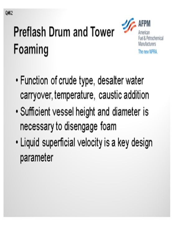
I want to reinforce some of Al’s points here. As he already mentioned, pre-flash tower or vessel foaming is a function of crude type salt or water carryover, temperature, and caustic addition. You are always going to have foaming occurring in a pre-flash drum or tower. The key here is to manage the foam and keep it in the tower. You must have sufficient vessel height and diameter necessary to disengage the foam. As Al also mentioned, the liquid superficial velocity is the key design parameter. It is important to keep in mind that the smaller the diameter of the vessel, the larger the foam height; so in narrow vessels, the liquid superficial velocity will need to be low in order to keep the foam height low. It is possible to add silicone-based antifoam to the pre-flash drum or tower, but consideration needs to be given to the downstream, gasoline, and distillate hydrotreater reactor catalyst.
DION (GE Water & Process Technologies)
Al and Kevin covered operational and mechanical issues regarding foam. Part of the question asked about the causes of foaming. There are surfactants in crude oil. Surfactants can be any organic molecule that has an atom that is not carbon or hydrogen, such as organic acids, organic amines, mercaptans, and other molecules with a polar group associated with them.

RUSSELL STRONG (Champion Technologies)
I have heard several comments that silicone antifoams in crude are problematic. There have been recent events offshore in the Gulf where so much antifoam was being used upstream that it was actually poisoning hydrotreater catalyst in the refinery from the upstream application. Other causes of silicone contamination can come from the crude while trying to control foaming in a flash drum or in a crude tower. To control those, silicone antifoams are sometimes used with occasional success. Several years ago, at a refinery down in the Houston, Texas area, I encountered severe foaming in a crude tower that would not go away. Standard silicone antifoams did nothing to solve the problem, but a fluorosilicone antifoam worked well. It was far more efficient and actually worked where the polysiloxane was deficient. It also offered less risk of downstream silicon contamination. So, keep this in mind as an option if you have crude unit foaming.
STEVEN FISCHER (Delek Refining)
At a previous refinery, we reintroduced the vapors to the flash zone with the result being quench to the flash drum that resulted in poor cutpoints. When we introduced the flash vapors from the flash drum to the flash zone, we saw that that the flash drum had actually acted like a quench, which could result in a poor cutpoint at the bottom of the crude tower.
SHELTON (KBC Advanced Technologies, Inc.)
Simulations do not indicate flash zone quenching if, as previously mentioned, the flash drum operating pressure is optimized to flash-only water. We have evaluated the flow schemes in models with the two streams mixed outside of the column and combined in the flash zone, but we get the same overflash.
STEVEN FISCHER (Delek Refining)
That was our assumption when we designed it that way, but our performance did not show that result. Our performance improved when we introduced it higher up.
ANDREW SLOLEY (CH2MHILL)
Addressing that last comment, I think what you are seeing there, when you see the poor performance, is the mixing of transfer line liquid with the vapor coming in, which is an issue with the equipment and not having the vapor segregated from the transfer line.
SHELTON (KBC Advanced Technologies, Inc.)
Our designs do have a separate flash drum vapor nozzle in the flash zone. It is important to have a pressure controller on the flashed vapor line, so the drum is not riding on the lower flash zone pressure. I do not know if that is your case or not. Do you have pressure control on the pre-flash drum? If not, a large pressure drop will produce a very high vapor rate, and then hydrocarbons will be flashed. In that case, there could be some quenching. We try to just flash the water and no hydrocarbons. When you think about it, if there were substantial light hydrocarbons, the desalter would overpressure. So, there are not a lot of light hydrocarbons in the crude because the only difference in the flash drum versus desalter operation is the desalter pressure, which is also low compared to the elevated hot train pressure.
STEVEN FISCHER (Delek Refining) We had some light hydrocarbons going overhead in addition to water.
SHELTON (KBC Advanced Technologies, Inc.)
There may also be recycle streams quenching the flash zone.
ROBERTSON (AFPM) Al, could you comment on the superficial velocity?
SHELTON (KBC Advanced Technologies, Inc.)
Liquid superficial velocity is a function of the vessel height versus diameter and design of the drum, which differs for vertical versus horizontal vessels. It is specific to each design and not a variable for an existing drum. Pressure is the important operating variable. If there is no pressure controller on the vapor from the flash drum, then that deficiency can be remedied online because there is usually a block valve at the column. In that case, the back pressure controller can be installed online.
VILAS LONAKADI (Foster Wheeler USA Corporation)
Is there any experience with the use of any internals in the pre-flash drums?
SHELTON (KBC Advanced Technologies, Inc.)
There are several types of feed distributors, including vortex tube clusters (VTC) and tangential nozzles. There are many effective feed distributors that will improve disengaging.
VILAS LONAKADI (Foster Wheeler USA Corporation)
Not about just the feed entry, but in the drum itself.
SHELTON (KBC Advanced Technologies, Inc.)
We do not recommend demisters on vapor outlets, and flash drums do not typically have any internals.
VILAS LONAKADI (Foster Wheeler USA Corporation)
Some vendors offer vortex tube clusters. I want to know if anyone has used them.
SHELTON (KBC Advanced Technologies, Inc.)
Yes, we mentioned vortex tube clusters (VTC), which have been used successfully in drums that operate at high velocities. We have also seen VTC distributors used for revamps to increase throughput at higher drum velocities. They have been very effective.
VILAS LONAKADI (Foster Wheeler USA Corporation)
Did it reduce foaming?
SHELTON (KBC Advanced Technologies, Inc.) Yes, VTC distributors have been used to solve foaming problems for existing vessels.
SHELTON (KBC Advanced Technologies, Inc.)
Foaming in flash drums and pre-fractionators is often caused by crude contaminants. Inorganic fines (sand, corrosion products, etc.), precipitated asphaltenes and sodium naphthenates formed from the reaction of caustic and naphthenic hydrocarbons have been identified as precursors. If caustic is injected at the desalter effluent, a simple solution is to move the caustic injection downstream of the flash drum to the pre-flash bottoms or hot train pumps.
The immediate solution to a foaming problem is to increase pressure to decrease vaporization. In a prefractionator, in addition to increasing pressure, higher reflux or wash rates will tend to knock down the foam front. Increasing temperature will reduce surface tension and mitigate foaming. Long term solutions include improving desalter operation (particularly solids removal) and improved selection of treating chemicals for the preheat train and desalters.
The design and operation of pre-flash drums and refluxed pre-fractionator columns are different. Vessel design (vertical versus horizontal) and disengaging height affect foaming. KBC design guidelines for pre-flash drums include height versus diameter, liquid superficial velocity versus vapor velocity, disengaging parameters, feed distributors and pressure. For any design, increasing operating pressure will reduce foaming.
Pre-flash drums are located in the hot crude train downstream of the desalters to flash water and suppress vaporization at the end of the hot train. Flash drum vapors on pressure control are routed to the crude column flash zone. Flash drum pressure sets the vapor rate and composition. Simulations show that water causes vaporization in heat exchanger services at the end of the hot train, not light hydrocarbons. Very light hydrocarbons would overpressure the desalters, if present. Simulations will determine the flash drum pressure required to remove dissolved water from the desalter effluent. The flash drum should be operated at the pressure required to remove water and no lower to reduce carryover of flashed crude. In the event of a foamover, the foam can be broken by temporarily increasing drum pressure to reduce vaporization. Good desalter operation with no water carryover to the flash drum will minimize foaming. Desalters should be operated with less than 0.5% BS&W in the effluent. Prefractionators are typically refluxed distillation columns with an overhead product such as light naphtha and may also have sidecuts. Foaming is less prevalent in a refluxed column. In the event of a foamover the foam front can be broken by first increasing reflux rate and if necessary, temporarily increasing overhead pressure.
BASHAM (Marathon Petroleum Corporation)
Foaming is always present in pre-flash drums and towers. It can be a function of several parameters including crude type, desalter performance (water carryover), drum or tower temperature, and caustic addition. Depending on its feed location in the atmospheric crude tower, pre-flash drum vapor can cause black distillate, black atmospheric gas oil, and increased atmospheric tower bottoms if the foam contains flashed crude. Similarly, in pre-flash towers foam with entrained flashed crude can cause black naphtha. The key to managing foam is keeping it in the pre-flash drum or tower.
A properly designed vessel (drum or tower) will allow sufficient height to disengage the vapor from the liquid. The most important design parameter is the superficial velocity of the flashed crude. The foam height is directly proportional to the liquid superficial velocity. The liquid superficial velocity must be sufficiently low enough to keep the foam height below the vapor outlet of the drum or tower. The foam height is also a function of the tower or drum diameter (cross-sectional area.): the smaller the diameter, the larger the foam height. This means that foaming will be a bigger concern in narrow vessels, so the liquid superficial velocity will need to be low in order to keep the foam height low.
It is possible to add silicone-based antifoam to the pre-flash drum or tower, but consideration must be given to downstream gasoline and distillate hydrotreater catalyst silicon loading.
LEE (BP Products North America)
A potential cause is water carryover out of the desalter that is vaporized in the flash drum. If there is water carryover and high shear stresses associated with a letdown valve with high pressure drop, this situation can generate small droplets which would contribute to foam generation. Foaming is often associated with high vapor rates, so a crude with a significant amount of vaporization at the flash drum conditions may have high potential for foaming. Antifoam use, and additional enhanced separations hardware, such as vortex cluster internals, can be considered.
DION (GE Water & Process Technologies)
Any organic molecules with atoms other than hydrogen or carbon are potential surfactants. Examples of such molecules are; alkyl phenols, organic amines, organic acids, and mercaptans. Foaming can be mitigated through the use of a defoamer or antifoam chemistry.Defoamers function by reducing the interfacial surface tension and viscosity. Antifoams function by modifying the interfacial surface elasticity. Most products commercially available from specialty chemical suppliers, such as GE Water & Process Technologies, function in both manners due to the behavior of their surfactant structure. The most effective defoamers in hydrocarbon environments are typically silicone based. If silicone poisoning is a concern, non-silicone-based defoamers, such as glycolic materials, are available.
BRUCE WRIGHT (Baker Hughes) Pre-flash tower foaming is most often caused by high solids loading coupled with high gas flows. Foam control with Baker Hughes Si-based antifoams has proven to be effective.
DENNIS HAYNES (Nalco Energy Services)
Crude viscosity, hydrocarbon polarity, solids content, caustic use, and vapor disengaging in flash sections and tower bottoms are discussed as causes for foaming. Antifoams have been around for quite a while that may be utilized in this area; however, the first step in corrective action is to determine that it is actually a stabilized foam layer and not tower flooding. There are instances where pre-flash towers are operated above design or have had some internal damage that causes flooding which is mistaken for foaming.
ANDREW SLOLEY (CH2M HILL)
One major cause of foam formation in these units is surface-active agents stabilizing the foam film on the liquid-vapor interface. Some of these agents are inherent components of specific crudes. However, many of them have been added to crude as well stimulation, drag-reducing, anticorrosion, or hydrogen sulfide scavenging additives. With continued production of heavier crudes and more aggressive well stimulation operations, foaming problems should be expected to get worse.
Solutions to foam formation include; antifoaming additives; foam-breaking inertial separators; and modifying operating conditions.
Silicone-based antifoaming additives can be effectively used. Their downside is that they vaporize and end up in the lighter products, particularly naphtha. This puts the antifoam into the downstream naphtha hydrotreater feed. Few hydrotreaters can tolerate this. Antifoams are rarely used.
Foam-breaking inertial separators have been used in a number of plants. They are derived from equipment design for oil production operations. In the oil fields they are proven technology. Experience in refineries, while limited, has been mostly successful. For certain plants and feeds they may be a choice worth serious consideration.
The most common method of avoiding foam-created problems has been to modify the plant operating conditions. This may include changes in feed rate, pressure, or temperature. Feed rate reduction increases effective residence time in equipment. It also reduces total vapor rate formation. While expensive, some plants are constrained to do this. Increasing pressure reduces vapor formation and increases vapor density. Both reduce the volume of vapor. Increasing operating pressure reduces foam problems. Temperature changes are more complex. Higher temperatures (at the same pressure) create more vapor volume, they also decrease liquid viscosity. These are competing changes. More vapor volume increases foam make. Lower viscosity speeds foam decay. In a plant with a foam problem, small temperature changes, in either direction, may help solve the problem. Experience has shown an operating temperature change as little as 10°F may change the vapor volume, or the viscosity, enough allow the flash drum or tower work, or be catastrophically worse.
Proper pre-flash installation includes balancing many factors including equipment size, expected operating conditions, and how to connect the pre-flash system to the existing unit. Revamps to add, or improve, pre-flash drums or towers need to be carefully evaluated.
Year
2012
Process
Question 63: Crude and vacuum tower off gas production from bitumen crudes can be quite variable depending on feedstock quality. Please comment on observed off gas production when processing bitumen crudes.
LEE (BP North America)
Our response to this particular question is based on the presumption that bitumen crudes include the conventional Canadian heavy supply of crudes such as Lloydminster and Cold Lake. There has not been much Canadian tar sands bitumen actually processed within BP, either as a synbit (bitumen diluted with synthetic crude) or a dilbit (bitumen diluted with condensate) as of yet. Some of this new bitumen supply includes supplies such as Christina Lake, Sunrise, and Firebag bitumen. The vacuum resid cut has a very high asphaltenes content, and we expect to see a significant cracked gas production rate. The cracked gas production will vary largely with the vacuum furnace thermal severity, mainly film temperature, residence time, and feed quality. We do not see any particular notable cracked gas production from many of our crude furnace operations.
There are other factors, besides those cited, that can also contribute to gas production. If the bottom surge volume in the vacuum tower has a long residence time, say above three minutes, and it is also unquenched, then gas can be generated by cracking in this zone. We typically like to quench this zone to less than 680°F or so. Another mitigating parameter for gas cracking is the use of coil steam to increase furnace tube velocity and minimize residence time and film temperature. Most of our high severity vacuum furnaces utilize coil steam.
We generally correlate the furnace feed quality to API gravity, but the feedstock factors need to be applied based on experience with the supply source. Generally, heavier, more asphaltenic crudes will produce more off gas at a given furnace temperature. Feedstock factors are important as we know that there are more reactive and less reactive asphaltenes content present. There are also not a lot of correlated or quantified experiences with gas production rates. We have found that our conventional Canadian heavy oil supply, for example, produces roughly one and a half times the gas make predicted by a base cracked gas correlation we use. We expect the synbit or dilbit supply to produce even higher cracked gas production rates. We also recognize that once a feedstock produces a significantly higher off gas production rate than this, it will likely become uneconomical to run higher severity furnace operation – that is, higher cutpoint operation – due to the costs associated with attendant coking, fouling, and other cycle life maintenance expenses.
Year
2012
Process
Question 64: Based on your experience, what are causes of fouling in the diesel/distillate draws of crude, vacuum, and coker fractionation towers? Does this migrate to downstream diesel hydrotreating units? What mitigation strategies are being employed to overcome these issues?
LEE (BP North America)
We have been concerned with potential phosphorous fouling on units processing Canadian heavy crude oil. We are aware that some refiners have experienced and reported on significant phosphorus fouling issues in the light diesel or jet draw section of the crude tower, as well as in the crude furnace. While we are concerned with the issue and monitor for it, we have not had any particular callout issues with CDU phosphorus fouling. In our view, the fouling of interest in the diesel draw section is differentiated from the amine or ammonia salt fouling that we typically see in the cooler top section of the tower. These particular salts condense at colder temperatures about less than 300°F, and we have not typically seen issues with these salts in the diesel section except for a particular example that I will describe shortly.
We have converted from conventional moving valve trays to fixed valve trays in the diesel section of a crude tower to help mitigate fouling. However, we have not yet definitively demonstrated the benefit of the modification as it is difficult to achieve site-by-site comparative conditions for doing such. This is a preemptive type of tower internals modification.
Many of our refineries are particularly concerned with any downstream unit impacts. We take phosphorus samples in our CDU products and closely monitor if issues are suspected or if there is a phosphorous-bearing crude scheduled or suspected to be in the crude supply. In the table below, you can see examples of some suspect Canadian crudes. The phosphorous contents are shown for these crudes. We monitor unit health and operations closely on our CDU blends that are in the 2 ppm to 3 ppm phosphorous content range.
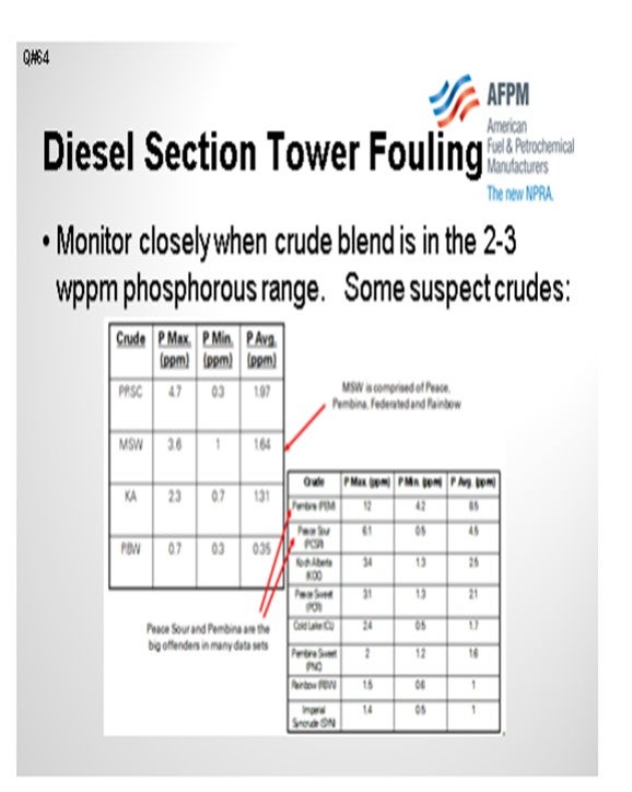
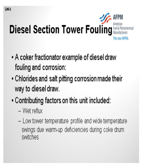
Let me add that one example I said I would give you. In this case, we did get some diesel section salt fouling. This one happened to be on a coker diesel draw tray. We saw nozzle corrosion on this unit that was due to chloride and salt pitting corrosion and which was the result of both wet reflux and lower tower temperature profiles during drum swings. This particular coker has had issues with wider-than-typical temperature swings during the coke drum switches and a relative deficiency of warmup capacity, both of which contributed to the lower temperature profile seen on the coker fractionator. So, chlorides in this coker naphtha and diesel products did find their way to downstream units in this particular refiner.
BASHAM (Marathon Petroleum Corporation)
We experienced a similar situation as Howard just mentioned. At our Robinson Refinery crude unit, we have seen phosphorous fouling over the kerosene section for about three to five trays. We also had floating valves that we replaced with a fixed valve design to help out with that fouling as well. In a coker fractionator tower, it is important that, as Howard said, you do not let the overhead temperature get too low; because when you force the colder temperatures down in the tower, you can see the salt formation in the distillate section.
DION (GE Water & Process Technologies)
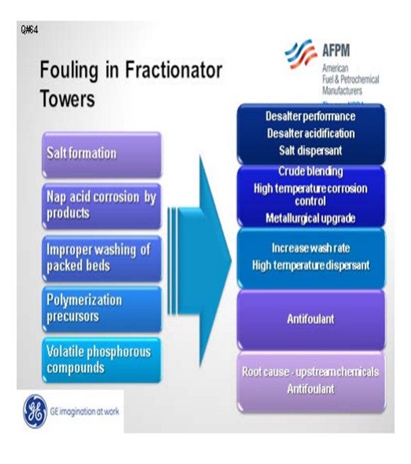
Fouling in the distillate trays and other locations can be divided into five different categories: salt, corrosion byproducts, coke, polymers, and volatile phosphorous compounds. Amine salt fouling can be mitigated with improved desalter performance, removal of tramp amines, and the use of a salt dispersant. Acidifying the desalter will partition a greater number of amines into the effluent brine.
If you do not have the proper metallurgy, corrosion byproducts can foul downstream units. This can be addressed with metallurgical upgrades and high temperature corrosion control programs, as well as blend control to minimize the TAN (total acid number) and NAN (naphthenic acid number) of the crude blend.
Improper washing of packed beds can contribute to fouling. This condition is usually seen in vacuum towers that have high surface area and very high molecular weight heavy hydrocarbon molecules that may precipitate, dehydrogenate, and create coke. This fouling can be addressed operationally with wash rates and the use of a high temperature dispersant to move coke particles.
Bitumen streams, such as dilbit from Canada and DCO (diluted crude oil) from Venezuela, may have the potential to induce polymerization. These crudes are typically bitumen with a diluent added to reduce viscosity. If these diluents come from cracking processes, there is the potential that they may contain olefins which could encourage fouling from polymerization products.
Howard addressed volatile phosphorus. These are most likely from phosphorus-based oil field chemical additives.
AHMAD AL-JEMAZ (Kuwait National Petroleum Company)
Again, I want to ask about mitigating fouling in the coker fractionator. Also, how effective is the introduction of online antifoulants to clear the fouling material created from corrosion products or coke fines and salts? Is there any record of successful implementation of antifoulants to clear the fractionators?
DION (GE Water & Process Technologies)
It is easier to prevent fouling from occurring than to remediate after the fact. An example is asphaltene precipitation. It is easier to prevent asphaltene molecules from agglomerating to a size where they precipitate than it is to redisperse them once they are agglomerated. Sloughing the tower to wash fouling material out of the system is usually a last resort. A better approach would be to examine methods to minimize coke entrainment into the tower including: an effective coker defoamer, defoamer to diluent ratio, coker overhead corrosion inhibitors, upward vapor velocities in coke drum vapor line, and an antifoulant in the gas oil or other reflux.
CELSO PAJARO (Sulzer Chemtech USA, Inc.)
For our delayed coker main fractionator, we have successfully used antifouling trays (VG AF™). They have several advantageous characteristics to mitigate fouling including fixed valves, push valves, fouling-resistant downcomer designs, and special outlet weirs. These features generally resist fouling and/or serve to move sediment across the trays to minimize accumulation of these fouling components.
LEE (BP North America)
I have one other comment on the first question: the use of antifoulants. Maybe the vendors know more about this, but I think there is some literature or some publications where folks have successively used iron dispersant to move around the iron scale. We considered that for the salted-up tower we had; but to us, it felt very much like a last resort because if we moved those solids to a draw nozzle or somewhere else, we would be shutting down the unit. So, we considered it, but we thought it was too risky to try.
BASHAM (Marathon Petroleum Corporation)
At Marathon Petroleum Company, the only issue we have had is the phosphorus fouling in our Robinson refinery crude tower, which only occurred over three to five trays in the kerosene section. We have reason to believe that phosphorus will migrate to both the kerosene and diesel sections, thus affecting the diesel hydrotreater. However, only the volatile phosphorus is believed to result in tower fouling. We replaced the trays (floating valve) with an antifouling fixed valve design.
DION (GE Water & Process Technologies)
There are five primary ways that foulants can be generated and deposited in the diesel/distillate sections:
Salt Formation: With more focus on diesel maximization, more tower operations have been changed to run at lower overhead temperatures. The shift in tower operation coupled with tramp amines either in the crudes or recycled via other streams can cause salting in the tower. The salts will foul the tower and since they are very corrosive, will end up generating corrosion byproduct which will also contribute to the fouling.
Naphthenic Acid Corrosion: Naphthenic acids can distill and concentrate in these cuts. If the temperature is high enough and the metallurgy has not been properly upgraded (SS 316L and SS 317L), corrosion will occur. Depending on the severity of the corrosion, the fouling rate from corrosion byproducts can be quite significant.
Improper Washing of Packed Section: This typically happens more in vacuum towers where packed beds are more common. There is more surface area for compounds such as asphaltenes and other heavy molecular weight material to deposit and dehydrogenate forming coke. Some of the coke fines will end up going with the draw and can foul the downstream exchangers.
Polymerization Precursors: With the increased availability of dilbit, synbit and diluted crude oil, there is an increased risk the diluent used for these synthetic crude or bitumen products are from cracking processes. If the diluent is from a cracking process and either not hydrotreated or the hydrotreater is not completely efficient, polymerization precursors can be present.
Volatile Phosphorous Compounds: With the increased availability of unconventional crudes, fouling from volatile phosphorous compounds is becoming more prevalent.
All of these foulants and foulant precursors have the potential to impact downstream units.
Mitigation Strategies
1. Salt formation:
a. Desalter performance improvement (chloride reduction)
b. Desalter acidification to reduce tramp amines
c. Salt dispersants
2. Naphthenic corrosion:
a. Crude blending to reduce naphthenic acid content
b. High temperature corrosion control program (chemical treatment)
c. Metallurgical upgrades
3. Improper wash:
a. Increase wash rate.
b. Apply high temperature dispersant.
4. Polymerization precursors
a. Apply antifoulant chemistry to minimize polymerization.
5. Volatile phosphorous
a. Perform root cause analysis of upstream chemical additives to minimize or eliminate the risk.
b. Apply of antifoulant chemistry, such as dispersant, to minimize fouling due to phosphorous compounds.
BRUCE WRIGHT (Baker Hughes)
Salt deposition is the most common. Both ammonium and amine chloride salts have been identified. The salts most likely will not migrate downstream, but can lead to additional iron sulfide formation, via underdeposit corrosion, which has been seen to migrate downstream. The deposition of the salts is a function of temperature and concentration. Identification of the operating window in which salts will deposit can be determined by use of the Baker Hughes Ionic Model. The Ionic Model can also be used to select the most appropriate neutralizer to reduce salt deposition for the operating window. Baker Hughes salt dispersant additives have also been successfully employed. iron sulfide fouling is also not uncommon. Effective mitigation has been achieved with Baker Hughes corrosion inhibitors and/or iron sulfide dispersant additives. Organic phosphorus compound deposition has also been experience. Both mitigation and online cleanup have been achieved with Baker Hughes additive application.
DENNIS HAYNES (Nalco Energy Services)
Diesel/distillate draw fouling in distillation columns is distinct from the problems reported in the literature for naphtha section fouling. Fouling that has been seen at this area lower in the tower, in certain cases, has been related to some specific chemicals used in the production of crude oil. The Canadian Crude Quality Technical Association has done projects in this area over past years. Where the fouling has become apparent in columns, dispersant type chemistries have been successful in reducing material buildup.
SAM LORDO (Nalco Energy Services)
In this part of the tower, amine/ammonia salting is the primary fouling encountered. The following has been done to minimize this type of following:
• Raise tower overhead temperatures,
• Optimize desalting operation to minimize chloride and/or amine traffic in the tower, and/or,
• Use salt dispersant chemistries.
Year
2012
Process
Question 65: Our vacuum column wash bed has lasted seven years in service and now needs to be replaced due to excessive coking and pressure drop. What is the typical life expectancy of the wash grid and packing? What is the panel's experience for the use of wash oil to the vacuum column wash section bed in gpm/ft2 (gallons per minute per square foot) with structured packing and/or grids in the bed? What is the recommended maximum slop wax draw temperature? Should a limit be set on this temperatu
SHELTON (KBC Advanced Technologies, Inc.)
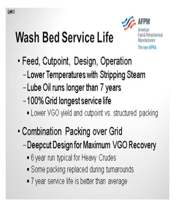
This topic was discussed extensively in the previous Q&A, so my response will focus on wash bed replacement after seven years due to excessive coking and pressure drop. The typical life expectancy of a wash bed has to be qualified. It is dependent on cutpoint, design of the column, internals, operation, and severity.
A wet operation with stripping steam requires lower coil outlet, severity, and flash zone temperature to achieve the same cutpoint compared to a dry operation. I will not address lube oil wash beds, which last considerably longer than a fuels operation. Obviously, a bed with 100% grid lasts longer than a deep-cut design with structured packing.
Since the run length is seven years, it is assumed this is combination packing over grid and a deep-cut design. For a heavy crude operation, six-year runs are typical. If it is a severe operation, then even with a well-designed wash zone with good overflash and adequate slop oil there are still some sections of the packing that have to be replaced during turnaround. With some asphaltic crudes, refiners are satisfied if they make a run without any incidents. So I would say that a seven-year service life is better than average in a severe operation.
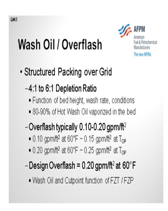
Regarding the specific wash oil flux rate, we try to avoid rules of thumb. Every operation is different and has to be modeled. In this kind of severe operation, the depletion ratio could vary from 4:1 to 6:1 and is a function of bed height and wash rate conditions. In a severe operation or deep-cut operation, we typically see 80% of the wash oil vaporized in the beds. KBC targets the overflash or the slop oil at the bottom of the bed, and the required wash oil rate at the top of the bed to produce that overflash target is variable.
It was interesting when we were talking amongst the panel. I would have thought this would have been the standard. Recent Q&A answers quote flux rates, but it was surprising that standard conditions or flowing conditions were never specified. At the low end, the cold versus hot flux rate varies by 35%.
Typical overflash flux rates range from 0.1 gpm/ft2 to 0.2 gpm/ft2 at 60°F, and 0.1 gpm/ft2 at 60°F is about 0.15 gpm/ft2 at operating temperature. In our designs, we target 0.20 gpm/ft2 overflash at 60°F at the bottom of the bed. The wash oil rate at the top of the bed is whatever is required to attain 0.20 gpm/ft2 at 60°F overflash at the bottom of the bed. Wash oil rate is a function of flash zone temperature and pressure. Hopefully, if you work on an operating unit, it has a slop oil meter. Then the wash oil rate should be adjusted to maintain the target overflash at the bottom of the bed. This is how we model an existing operation that does not have a slop oil meter. Frequently, the wash oil to the top of the bed is measured but not the slop oil or overflash.
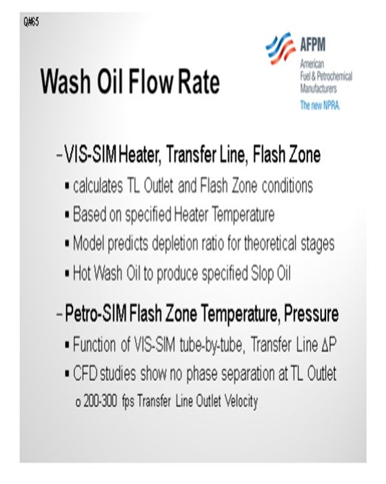
For an optimization or a grassroots design, we develop a fully-integrated model of the vacuum heater with our VIS-SIMTM model, including the transfer line and the wash zone in the column. The overflash in the column model and the heater outlet temperature are specified.
Petro-SIMTM accurately predicts the depletion ratio based on theoretical stages, and the wash oil rate at the top of the bed is variable. The answer to the target wash oil rate is whatever is required to produce the desired overflash at the bottom of the bed and which will ensure that the wash bed will operate trouble-free for a run-length.
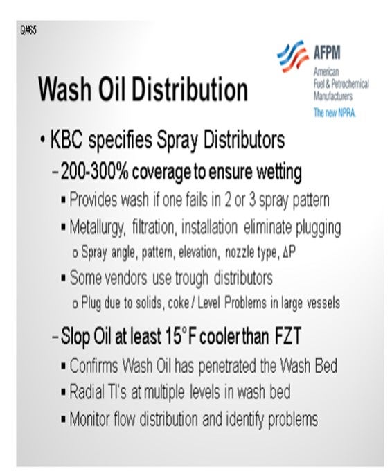
Discussions about wash oil should include inlet distributors because this is critical. In our grassroots designs, we specify spray distributors with 200% to 300% coverage; so, in any one spray pattern, even if one or two spray nozzles fail, there is still coverage in that zone. Some vendors use tough distributors, but we have designed 47-foot ID (inside diameter) vacuum columns. It is difficult to install a level gravity flow distribution system in a very large diameter column. Furthermore, in a deep-cut severe operation, we would be concerned about coke solids plugging the gravity troughs. With any distribution system, proper metallurgy is very important with a good filtration system to remove solids from the wash oil.
The final question was about the recommended maximum slop wax draw temperature. The slop oil temperature should be cooler than the flash zone, which confirms that the wash oil has penetrated the bed and will not coke. As far as a maximum temperature, Kevin thought this might have to do with pump seals.
BASHAM (Marathon Petroleum Corporation)
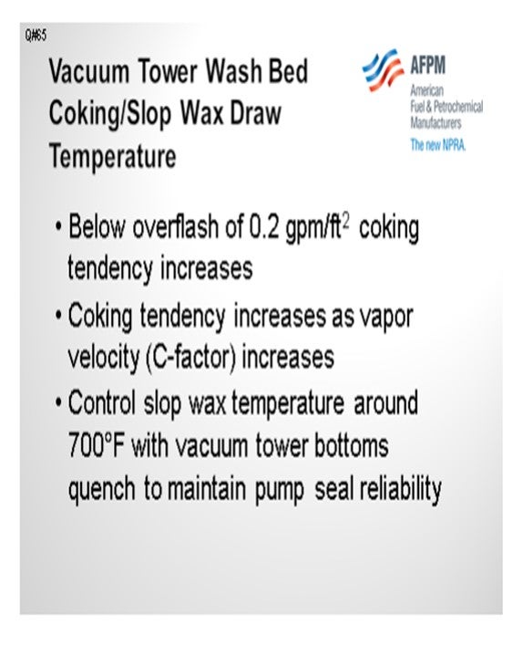
In our experience, if the wash bed temperatures get up over 770°F or so, the coking tendency will go up. We have had beds in mild service that have lasted over 10 years. We have had beds in severe services that have only lasted a couple of years. As Al was saying, it really depends on the severity of the service. In regard to the maximum slop wax draw temperature, one of the considerations needs to be the slop wax pump seal integrity. We try to keep the slop wax pump temperature below 700°F. We do that with vacuum tower bottoms quench that is cooled and put back to the pump suction.
CLAY MARBRY (Roddey Engineering)
Does anyone on the panel or in the audience have any experience with recycling spent wash oil from the vacuum tower, not back to slop but to the vacuum heater inlet?
SHELTON (KBC Advanced Technologies, Inc.)
We have modeled slop oil recycle or overflash to the vacuum charge heater several times. It does not accomplish anything, except in a lube oil operation, because lube slop wax is very light and paraffinic. But in a deep-cut fuels operation, 75% to 80% of the slop oil is resid. Vacuum charge heater excess duty is better utilized by increasing feed rate or increasing heater outlet and flash zone temperatures to lift more gas oil product.
LEE (BP North America)
I will add that in our experience, we recycle the slop wax to the furnace inlet on several of our units, maybe 40% of them. However, we do find that if you are at a furnace outlet temperature limit, the slop wax recycling will cost you more duty; however, it will give you more lift. You do get a cutpoint gain, but you have to judge your unit limit.
CORY NOYES (Marathon Petroleum Company)
How do you typically set the wash rate typically? Is it done once and verified with lab results, or is anyone trying to automate that wash rate effectively based on the energy balance around the slop wax tray?
SHELTON (KBC Advanced Technologies, Inc.)
As mentioned, our models specify the overflash at the bottom of the bed, which includes the column energy balance and produces the wash rate at the top of the bed. We optimize the packing versus grid and bed height, which affects the depletion ratio. However, with some grid at the bottom of the bed, it is difficult to attain two theoretical stages because the packing height becomes excessive. In theory, we target two theoretical stages for good, deep-cut separation. In our grassroots designs, we specify radial thermowells at three levels in the wash bed. Unfortunately, after detailed design and cost cutting, very few of our units have wash bed radial temperature indicators at multiple levels. We prefer to monitor what happens in the wash zone, but there are only a few units with radial temperature indicators. We would like to see the wash zone operation optimized by monitoring temperature gradients, overflash, and HVGO yield and quality. But again, we target sufficient wash at the bottom of the bed to prevent coking.
SHELTON (KBC Advanced Technologies, Inc.)
Wash zones with 100% grid will last longer than wash beds with combination grid at the bottom and structured packing on top of the grid. For the same operating conditions, the grid will not produce the VGO recovery or the cutpoint that can be achieved with structured packing. Deep-cut designs for maximum VGO recovery are typically combination beds. There is no typical service life for vacuum column wash beds, and KBC is not aware of any vendors that provide guarantees. Crude type, severity of the operation and column design affect run lengths. The same cutpoint can be achieved at a lower transfer line temperature in a wet design with a bottoms stripper compared to a dry operation with no bottoms steam. Lube oil operations typically operate at low cutpoint with high quality, paraffinic feeds and will not be included in this discussion. Lube oil run lengths would be longer than seven years.
In fuels refineries, wash zones operate well for the normal four- to six-year run between scheduled turnarounds. For heavy crudes with high asphaltenes in deep-cut operation some sections of packing typically require replacement during turnarounds. If the question has been posed by a refinery operating under these severe conditions, a seven-year service life is better than average, particularly when processing heavy crudes at high flash zone temperatures associated with deep-cut operations.
Wash beds with structured packing over grid have wash oil depletion ratios of 5:1 to 6:1, depending on bed heights and operating conditions. Approximately 80% to 90% of the hot wash oil flow to the top of the bed will be vaporized in the bed. Targets for minimum wash oil penetration through the bed or overflash (slop oil) at the bottom of the bed are often quoted as 0.10 gpm/ft2 to 0.20 gpm/ft2 . It is important to specify if the flux rate is calculated at flowing or standard conditions. The 0.10 gpm/ft2 overflash flux rate is usually at 60°F, which is equivalent to 0.15 gpm/ft2 at operating temperature. KBC designs for 0.20 gpm/ft2 at 60°F standard conditions. Petro-SIM™ oil characterization produces the corresponding wash oil rate at the top of the bed without adjustment or design factors.
Accurate flash zone conditions are difficult to obtain for operating units. For prediction cases and vacuum unit design, KBC employs integrated VIS-SIM models of the fired heaters, transfer line and vacuum column to calculate transfer line outlet and flash zone conditions. For a specified heater outlet temperature, Petro-SIM™ accurately predicts the depletion ratio based on theoretical stages and the amount of wash oil required at the top of the bed to produce the target overflash or slop oil at the bottom and minimize coking. CFD studies show that phase separation does not occur at transfer line outlet velocities of 200 fps to 300 fps in properly designed piping configurations. Predicted flash zone temperature and pressure are a function of accurate model results for heater tube-by-tube and transfer line pressure drop profiles.
Wash Oil Coverage and Distribution: KBC specifies spray distributors designed for 200% to 300% coverage to ensure full wetting of the wash bed. Some vendors concur, and others specify trough distributors due to concerns about potential entrainment of atomized wash oil. In our experience, entrainment is more dependent on vapor velocity, the design of the flash zone inlet distributor, and the wash zone spray distributors (spray angle, pattern, elevation above the bed, nozzle type, and pressure drop). Trough distributors in the wash zone can plug due to solids and coke. Uneven level of gravity flow distributors in large diameter vessels can result in inadequate coverage of the wash bed. KBC designs spray distributors so that wash bed coverage is maintained if one of the double or triple coverage spray nozzles fails in any single spray pattern. Proper wash oil system design, metallurgy, filtration and installation can eliminate spray nozzle plugging. Although usually omitted during final design, KBC process designs specify radial temperature indicators at multiple levels in the wash bed to provide indication of flow distribution through the bed and identify problem areas.
Recommended Maximum Slop Wax Draw Temperature: The slop oil liquid temperature should be approximately 15°F cooler than the Flash Zone temperature to confirm that the lighter wash oil (HVGO) has penetrated the Wash Bed and mixed with the overflash (slop oil).
A limit should not be set on this temperature; it should be cooler than the flash zone.
BASHAM (Marathon Petroleum Corporation)
This depends on severity of the operation. As temperatures increase above 770°F, then life expectancy drops. Also, as C-factor increases, life expectancy drops. As overflash drops below 0.2 gpm/ft2 , then life expectancy drops. We have beds that have been in service for over 10 years in mild service. We have had beds in severe service that last only a couple of years. In regard to the maximum slop wax draw temperature, a primary consideration is slop wax pump reliability. To maintain pump seal integrity we recommend a maximum temperature of 700°F, which is achieved with vacuum tower bottoms quench.
LEE (BP Products North America)
We have had a grid wash bed last 20 years in Alaskan North slope service. When it was finally removed due to suspected performance issue, it was found to be in pristine condition and the bed could have gone at least another five years. We do not think a temperature limit per se is necessary, but more of maintaining an appropriate minimum bed wetting rate for the conditions and feedstock.
DENNIS HAYNES (Nalco Energy Services)
The use of KOH (potassium hydroxide) is limited compared to the more abundant use of NaOH, so there is comparatively fewer field data for KOH. It should react similar to NaOH regarding the ability to reduce chlorides for atmospheric overheads. One reason that some refiners are evaluating it is in order to reduce sodium content going to downstream conversion units, such as coker. The use will reduce sodium going downstream where there is concern in keeping this specification in greater control; however, potassium is also known to have properties (such as hydrocarbon dehydrogenation) that may increase coking. Potassium is assumed to have less detrimental properties than sodium but is not a total solution to downstream concerns.
ANDREW SLOLEY (CH2M HILL) Wash bed coking tends to be a catastrophic problem. Either the unit cokes or it does not. Many plants have achieved 20-year, or longer, service life without having a coked bed. Bed coking is caused by excessive liquid residence time at high temperatures. Keeping liquid flowing over the bed keeps the residence time down. The accepted minimum liquid rate on the bed is 0.15 gpm per square foot at the lowest liquid loading point. This will be at the bottom of the bed. Plant data has shown this liquid rate is the same for both grid and reasonably open structured packing. This value assumes good distribution of both the liquid and the vapor to the wash bed.
In operation, the plant meters or controls the liquid to the top of the bed. Liquid dryout ratios across the bed may vary from 5:1 to as high as 15:1. If the bed dryout ratio is higher than expected, the bottom of the bed will coke. This dryout ratio depends upon the pressure drop across the bed, fractionation efficiency of the bed, transfer line performance, crude composition, and cutpoint of the unit.
Very little evidence of coking will be seen for the first 10 to 14 months. After that point most units will see a noticeable pressure drop rise across the bed. However, once formed, further coking is inevitable.
A few plants chose to deliberately run with excessively low liquid rates. The objective of these plants is to tradeoff a long period with higher liquid yields (due to lower wash oil rates) versus a short period of time with lower yields due to pressure drop. The economics of this operation seem doubtful for a typical facility. The temperature difference between the slop wax collector liquid and the flash zone is more important than the absolute temperature of the flash zone. The more liquid that leaves the wash bed, the lower the slop wax temperature compared to the flash zone temperature.
The temperature difference sufficient to prevent coking will vary with the unit. The temperature difference resulting from sufficient liquid will go up if the vapor and liquid distribution to the wash bed gets worse. To maintain a minimum liquid rate at all points of the bottom of the bed, more total liquid is required.
Careful design and installation of the liquid distributor and slop wax collector tray is amply justified. So are effective control systems to monitor bed performance.
Year
2012
Process
Question 66: Some refiners are considering substituting potassium hydroxide for sodium hydroxide as a desalted crude treatment to lower overhead chlorides. What is the impact of this change on coker operation and other downstream units? What are the advantages and disadvantages?
DION (GE Water & Process Technologies)
They are both alkali metals. Potassium hydroxide should, in theory, act like sodium hydroxide. The effect should be similar with regard to reducing the overhead chlorides in the desalted crude or, similarly, in metal-catalyzed fouling. Potassium hydroxide does have the potential to be used as a tracer; for instance, it can be injected in the desalted crude. The bottoms and heavy gas oil fractions can be analyzed for potassium to determine the disposition of adding an alkali metal to the desalted crude. Potassium hydroxide is typically more expensive than sodium.
DION (GE Water & Process Technologies)
Potassium is an alkali metal just like sodium. Its ability to reduce the overhead chlorides is expected to be comparable to that of sodium. Just like sodium, it will contribute to metal catalyzed polymerization in downstream units. There is no known advantage to using potassium other than the fact that it can be used similar to a tracer to quantify the impact of metal hydroxide addition to downstream units. Potassium hydroxide is typically more expensive than sodium hydroxide. While there are no common potassium specifications for finished fuels, its potential negative impact in the fuel should be similar to that of sodium.
BASHAM (Marathon Petroleum Corporation) Potassium hydroxide is more expensive than sodium hydroxide. It is expected that the potassium ion will catalyze the cracking reaction and promote coking in the same manner as the sodium ion. Therefore, we do not see an advantage in using potassium hydroxide.
LEE (BP Products North America)
Sodium chloride is a very stable chloride and has a very high temperature for hydrolysis. We are not sure that there is any benefit from using potassium chloride as a base to control the overhead chlorides. We think that sodium will catalyze coke formation in the vacuum and coker heaters at concentrations of over 15 ppm. We think that potassium will do the same thing. Sodium is a poison for the downstream hydroprocessing units and so is potassium. We are not sure there is any benefit here.
ANDREW SLOLEY (CH2M HILL)
Potassium hydroxide has a lower potential to induce stress corrosion cracking than sodium hydroxide. Little direct experience is available to quantify this. However, test work targeted at syngas systems showed significantly increased temperatures were required for stress corrosion cracking to occur. This may be a benefit for the crude unit between the desalter and the crude tower.
Year
2012
Process

Question 67: We have an atmospheric overhead system with inadequate waterwashing,and we experience fouling and corrosion issues in the bundle. What might be the pros and cons of making a bundle modification or installing direct water spray into the shell side of the atmospheric tower overhead condenser in terms of underdeposit corrosion and bundle life?
SHELTON (KBC Advanced Technologies, Inc.)
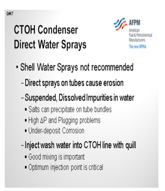
We would not recommend direct water sprays into the shell, regardless of whether this is the first overhead condenser, because direct sprays can cause many problems, including erosion. This is why vapor inlet nozzles have impingement plates in shell-and-tube heat exchangers. Solids may also precipitate, causing pressure drop problems and underdeposit corrosion. Typically, washwater is injected into the crude tower overhead line. I used quills so it would fit on the slide, but vendors supply sophisticated spray nozzles for good distribution. Mixing is important, but identifying the optimum injection point is critical. In this case, it is probably a crude overhead condenser; however, the entire overhead system should be modeled. Injection points vary for cold versus hot reflux systems. There can be combination air coolers, water trim coolers, or air-only coolers. Some overhead systems have banks of air coolers and then several water trim coolers in series. So, the optimum injection point must be determined by simulation.
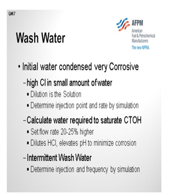
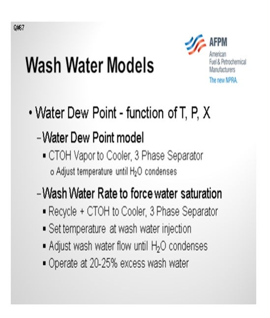
First, determine the water dew point, and be sure that the column overhead temperature is operating well above the water dew point. Calculate the water required to force saturation, and operate at 20% to 25% higher. To minimize corrosion, hydrogen chloride must be diluted with a large volume of washwater to elevate the pH of the water phase. Each operation must be analyzed by simulation. As I said, the first step is to determine the water dew point.
Maintaining the overhead temperature well above the water dew point is less challenging when maximizing gasoline with full-range naphtha overhead product. This becomes problematic when maximizing distillate, which lowers the overhead temperature. For distillate operations, there are potential dew point problem in the column; so, it is important to do the process engineering. We use several models. In one model, the crude column overhead vapor is sent to a three-phase separator with a cooler. A logical adjust operation varies the temperature of the cooler until the first drop of water condenses. That is the water dew point. The column and overhead line should be operated 15ºF to 25ºF above that temperature.
We set up a similar model to determine the target washwater rate for operation. Recycled washwater, plus the overhead streams, are fed to a three-phase separator with a cooler; so the temperature can be adjusted to simulate any point in the overhead system. Then with a logical adjust, the flow of water is increased until the first point of saturation or until the first pound of water condenses. We recommend operating with 20% to 25% additional washwater above the water saturation point.
It sounds fairly simple, but what dramatically affects the dew point is the equation of state model, be it Peng-Robinson, SRK (Soave-Redlich-Kwong), or a vapor pressure type.
CLIFFORD (Motiva Enterprises LLC)
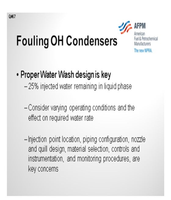
My response is very similar to Al’s. Going after waterwash improvements is really the key to preventing fouling and issues on the overhead condensers. Twenty-five percent of the injected water must remain in the liquid phase. You need to consider varying operating conditions and their effect on the required washwater rate. Variability in crudes and yield structures in your unit will change the conditions in the overhead system. Key factors in the proper design of your waterwash include injection point location, piping configuration, nozzle and quill design, and materials. As Harold mentioned, there is a P&P on waterwashers this afternoon.
DION (GE Water & Process Technologies)
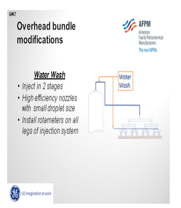
We recommend injecting the overhead waterwash in two places: into the overhead line and then individually into each leg of the overhead system. Use a very high efficiency nozzle to achieve atomization and good distribution of water droplets into the vapor phase. Then install a flow indicator, like a rotameter, on the waterwash to each of the overhead legs to ensure adequate water flow rate in each. It is extremely important to address the whole program – the waterwash, dew point, and salt point – because 90% of the corrosion occurs 10% of the time.
Regarding bundle modification, one refiner was limited on the amount of washwater he could use due to the size of his overhead. An impingement plate was removed and chevrons installed to direct the flow, and sacrificial tubes were utilized in the exchanger. That seems to have worked well because it channeled the corrosion to the sacrificial tubes while minimizing corrosion in other tubes.
RUSSELL STRONG (Champion Technologies)
First, I will also put in a promotion for this afternoon’s P&P because we are going to be talking about waterwashes. Here is a teaser: If you look at the high velocity in an overhead, it is certainly not at equilibrium at any point in the overhead line. So today, you will see computer flow simulations that show the immediate distribution effect of various waterwash spray nozzles in an overhead. We will also share thermography that shows the inefficiency of some waterwashes and why many of the waterwash rate calculations do not accomplish the end objectives. As far as the spray nozzles in the bundle are concerned, there is an option to put a nozzle into the bundle. There has been a successful case where there was a bundle on which you could not quite get water to the extremities. The top tubes were actually reconfigured by drilling through the tube sheet into those tubes where waterwash was then supplied. Holes were drilled into the tubes along the top and provided supplemental wash inside the bundle, which seems to have worked. Some people can get creative and come up with solutions that you would not have ordinarily imagined.
UNIDENTIFIED SPEAKER
So far, I think we have been addressing waterwash on a shell side. There have been some of these exchangers done with condensing on the tube side where waterwash was used on the tube side onto the tube sheet with the injection through the head of the exchanger onto the tube sheet. This put water down all of the tubes inside the exchanger. So, I think it is a little different from the previous discussion.
SHELTON (KBC Advanced Technologies, Inc.)
Direct injection of washwater through sprays installed in the shell of a shell-tube heat exchanger crude column overhead exchanger is not recommended for several reasons.
• Direct sprays on the tube bundle can cause erosion, which is why most designers specify impingement plates below the vapor inlet nozzles.
• Recycle washwater contains suspended and dissolved impurities such as salts which can precipitate on the tube bundles resulting in high pressure drop and plugging.
• Salt deposition on the outer surfaces of the tubes can result in underdeposit corrosion, tube leaks, unscheduled shutdowns and reduced tube bundle life.
Inadequate waterwashing causes localized corrosion, fouling and underdeposit corrosion. Adequate waterwashing in crude column and conversion unit fractionator overhead systems is so important that KBC has specific Best Practices for each service. Since an entire P&P session is devoted to Best Practices for crude unit overhead waterwashing, this response is an overview.
The initial water condensed in crude column overhead systems is very corrosive due to high concentrations of chloride ions in a small amount of water. Provision should be made for water injection at the point of initial condensation to minimize corrosion. KBC’s Best Practice is to calculate the washwater rate required to saturate the overhead stream and set the flow 20% to 25% higher. KBC grassroots crude unit designs are based on 25% excess washwater. This safety margin ensures that sufficient water is present at the point of initial water condensation to dilute the HCl and elevate the pH to minimize localized corrosion.
The water dew point is so important that it should be determined by rigorous simulation, not with a “rule of thumb”. Process simulators categorize water as a separate third phase. Accurate water dew point is a function of temperature, pressure and composition, including the water phase. Many physical properties are calculated on a dry basis. Thermodynamic models such as PR (Peng-Robinson) versus SRK (Soave-Redlich-Kwong), vapor pressure versus EOS (Equation of State) packages, and pseudo-component characterization produce different water dew points and flashpoints. KBC rigorously models the point of water saturation to determine the water dew point. Two simulations are required to calculate the water dew point and washwater rate required to force water saturation.
In a water dew point model, the overhead vapor feeds a cooler and three-phase separator with a Logical Operation to adjust the cooler outlet temperature until the first ounce of water condenses in the third-stage separator. This method provides an accurate water dew point to determine if the overhead temperature is operating with sufficient safety margin to avoid condensation in the column. Water dew points should also be checked at the inlets to each of the downstream services in the overhead system and the intermediate exchanger banks.
The next step is to develop a similar model with makeup, recycle washwater combining with the overhead vapor, feeding a cooler and three-phase separator. The cooler outlet is specified to match the operating temperature at the point of continuous washwater injection. A logical operator is used to adjust the washwater rate until the first ounce of water condenses in the third-stage separator. The model calculates the wash rate at the conditions for water saturation. For operating units, the washwater target flow rate should be set 20% to 25% above the theoretical rate required to saturate the stream.
The amount of water recirculation for saturation is a function of crude slate, column operating conditions and overhead product cutpoint. The theoretical rates required to saturate streams at the point of continuous water injection, as well as other points in the overhead system, should be calculated frequently to adjust washwater targets and identify requirements for intermittent waterwashing of upstream services in the overhead system.
The location of a continuous washwater injection is dependent on the design of the overhead condensing system because the water dew point depends on heat exchange configuration.
Hot Reflux Drum / Cold Product Drum (two separate vessels):
• Cold crude versus hot reflux exchangers should operate hot to avoid water condensation.
• The waterwash injection point is determined by the configuration of the cold product cooling. Some examples are listed below.
• For air coolers with water trim coolers, water injection is typically at the trim coolers.
• For air cooled condensers without water trim coolers, water injection is typically at the air cooler inlet nozzles.
• Water coolers only are multiple banks in series, and injection is typically between shells.
Combined Reflux and Product Drum with Cold Reflux:
• For 100% cold reflux with no top pumparound, the waterwash injection point varies for the following configurations:
- Crude overhead versus cold crude heat exchange,
- Air cooled condensers,
- Air coolers and water trim coolers, and
- Water condensers
• For 100% top pumparound heat removal with minimal cold reflux, the washwater injection point is determined by cold product cooling: air coolers with and without water trim coolers, or only water coolers.
Piping and injection points for intermittent waterwash should be provided for services that do not require continuous waterwashing. Some operators conduct intermittent waterwashing because of increased pressure drop in the overhead system. The frequency of intermittent waterwashing should also be based on the propensity of salt deposition determined by process simulations, fouling and ionic models.
CLIFFORD (Motiva Enterprises LLC)
Each option presents an opportunity to improve fouling and corrosion resistance. Bundle modifications as I understand it would be to improve the flow patterns at the point of fouling such that the fouling is not concentrated in one area. This would give the cooling in the bundle a chance to increase the amount of liquid water, and prevent further fouling and corrosion. This option is relies on fairly constant salt point/water points to achieve the desired performance improvements. If water dew point is shifted further downstream it may not achieve the desired level of success. Modifications which add additional nozzles to direct sprays to areas susceptible to fouling may increase the risk of damage to the bundles due to impingement of the spray onto the bundle. Pressure equipment engineering should also be consulted when adding nozzles to existing equipment.
Another option may be to improve the metallurgy such that it is more resistant to the corrosion mechanism and monitor differential pressure. It may be possible to bypass and waterwash exchangers for a short period to time to remove the deposited salts and restore performance, however this poses risks as it may move corrosion into downstream equipment not designed to handle this mode of operation.
A more robust solution would be to enhance the waterwash. This does not come without technical challenges which must also be addressed. Proper Injection point location, piping configuration, nozzle and quill design, material selection, controls and instrumentation, and monitoring procedures, are key concerns. Sufficient contact time must be provided to ensure that the HCl vapors are contacted by the liquid and neutralized. Spray pattern is important as ensuring a continuous aqueous phase along the pipe wall is important to prevent localized concentration cells from developing and causing accelerated corrosion. Impingement on downstream equipment should also be avoided as this may cause erosion/corrosion concerns. A rule of thumb is to maintain injection rates such that at least 25% remains liquid at the point of injection.
Alternate modes of operation including varying temperatures and mass rate should be considered to ensure that the system is robust enough, and monitoring should be in place to know when to adjust the rates. Finally, the impact of the increased water on downstream separations equipment should be considered, as well as the potential shift in duties to the downstream exchangers.
Injection of the water directly into or immediately upstream gives very little contact time, so the downstream bundle essentially functions as a static mixer forcing contact with the hydrochloric acid vapors and the aqueous phase. Because there is no guarantee that the neutralization amine will be immediately present where the HCl condenses, this bundles metallurgy should be carefully selected.
DION (GE Water & Process Technologies)
Waterwashing is used to provide a means of forcing the water dew point further upstream in the overhead system and to physically dilute and wash salts. This is accomplished by raising the amount of free liquid water in the system. This free water will then dilute corrosive species at the ICP and also wash away any neutralization salts formed at temperatures below the wash injection temperature or mixed exit temperature (MET). Water-washing of the overhead system is a beneficial and essential part of proper overhead maintenance. Modification of the bundle metallurgy to a higher corrosion-resistant material will increase the durability of the metal surface but will only delay failure and not prevent it. With the continued accumulation of precipitated salts, underdeposit corrosion potential is still present and fouling of the exchanger will continue to be an issue. In addition, the metallurgy involved in the bundle materials upgrade will be expensive and may not provide the bundle life and return on investment initially anticipated.
On the other hand, direct water spray into the overhead condenser delivers several benefits compared with a metallurgical upgrade. A properly designed waterwash will dilute acidic species at the initial condensation point (ICP) and physically remove the corrosive salts by washing them away from the metal surfaces. An adequate waterwash will also eliminate the need to upgrade the bundle metallurgy to a more expensive material. There are documented cases of bundles lasting 10 to 15 years due to the proper implementation of an overhead waterwash system. However, the overhead accumulator boot has to be large enough to accommodate the additional water volume and still provide acceptable separation of water from the hydrocarbon stream. Water carryover in the overhead reflux can introduce high levels of water-soluble amine back to the distillation column. This causes a large cycling effect that will dramatically increase salt points. Additionally, the water can cause wetting of forming or already existing salts. This in turn causes their characteristic corrosion rates to increase significantly.
A poor waterwash can be worse than no waterwash. Waterwash should be injected in two stages using high efficiency nozzles in a cocurrent configuration to provide a small droplet size with large surface area and dispersal pattern. This will impact both the wall wetting capability of the spray, as well as the vapor scrubbing efficiency. The first injection stage would be a single point injected into the overhead vapor line near the top of the column, while the second stage would be multiple points injected in parallel just prior to exchangers. In a well-controlled unit, the first-stage wash injection should provide just enough water to form 20% of total liquid water and primarily saturate the overhead vapor. The second injection stage then would inject the remainder of the total waters needed to achieve the washwater target. Enough water should be added to achieve at minimum 5% free water. While 5% is a minimum value, 10% to 15% waterwash can be even more effective. To ensure proper volumes and distribution of the washwater in the overhead system, it is critical to install rotameters on all legs of the injection system and maintain proper balance and monitoring of these flows on a routine basis. A GE client has also experimented with the mechanical changes to problem exchangers instead of installing washwater injection ports into the shell. The impingement plates on these exchangers were removed and replaced with chevrons welded just below the inlet to direct flow axially as the overhead stream entered the exchanger. To compensate for the increased impingement at the exchanger inlet created by these modifications, sacrificial tubes were installed wherever increased impingement resulted due to the mechanical changes (in this case, on the top of the bundle). The client reported that after making these modifications, the exchanger problems related to salt fouling were significantly reduced.
RANDY RECHTIEN (Baker Hughes)
Exchanger bundle modification and water injection (via multiple points) into the shell side of the exchangers have been implemented in the past; however, the success of these techniques has been limited. For those systems where a waterwash is already in place, more benefit can be realized by redesigning the waterwash so that it performs as required. Such modifications may include:
• Increased water flow rate,
• Installation of atomizing spray nozzles, and
• Relocation of wash injection points further upstream of condensers.
BASHAM (Marathon Petroleum Corporation)
We have never tried to put direct water spray on the shell side of a bundle. While the idea has merit, it requires multiple water injection nozzles and bundle modification to provide free area just below the nozzles so the water will spread out. Potential problems are water impingement leading to tube failure and reduction of condensing duty.
LEE (BP Products North America)
For corrosion mitigation, the tower should be completely dry or have adequate waterwash. As the crude tower normally has stripping steam in it, the overhead system is not able to be dry so the only option available is to have enough water that the water dew point is higher than the salt point so that water condenses first and is present in sufficient quantity to dilute the salts as they dissolve into the aqueous phase. Adequate waterwash also requires enough residence time to separate out the water from the hydrocarbon so that there is not water carryover into the hydrocarbon stream. Good contact and mixing are needed to adequately wash the inlet stream. Depending on the direct water spray configuration, there may be a compromise in this respect, but the suggested geometry is probably better than doing nothing.
DENNIS HAYNES (Nalco Energy Services)
If the modification allows for better dispersion of the washwater through the exchanger so that areas of less liquid traffic are contacted, it would be an improvement, and this has been done in rare cases in the industry; however, if the water flow rate is too low, the risk is that it may not be enough to wash salts out of the system resulting in elevated corrosion due to damp salts.
MARK ANDERSON (ThioSolv, LLC)
It is difficult to get adequate water distribution through the shell side of S&T (shell-and-tube) exchangers. There are a few measures which can help:
1) If the condensers are two-pass on the shell side, make sure the seals between upper and lower pass are intact. Leakage not only reduces the heat transfer, but it also allows the washwater to bypass large parts of the bundle, which allows heavy accumulation of solids in the unwashed spaces.
2) Provide a high washwater flow rate by recycling water from the reflux drum boot to. Distribute the washwater into the inlet of each condenser train with its own FI and globe or needle valve. The recycle water stream may be drawn from high in the boot because it does not matter if some hydrocarbon is entrained. That allows the vertical velocity in the lower part of the boor to remain low to minimize entrainment of hydrocarbon in the net sour water stream. Make sure the drum internals are designed to provide effective oil/water separation.
3) One can visualize that as the process stream passes around the side of each baffle in the exchanger, the liquid phases will not turn the corner as sharply as the gas phase. Deposits form on the downstream side of the baffle because of the water “shadow”. Water distribution can be improved by notching the circumference of the baffle plate to allow some liquid to leak past the closed side of the baffle. When fabricating a new bundle, specify that small holes be drilled through the baffle plate to allow liquid leakage into the liquid shadow.
4) Make sure that the type and amount of neutralizing and filming amines injected are not part of the problem rather than part of the solution.
Year
2012
Process
Question 68: After the operating temperature of the crude column overhead has been raised, corrosion rates in trim coolers’ inlets have increased greatly. Ultrasonic thickness (UT) measurement has indicated some increase in local thinning, but not to the degree of actual damage. What are new trends for monitoring corrosion in distillation columns and overhead condensing systems?
CLIFFORD (Motiva Enterprises LLC)
When we talked about this on the panel, we had some very interesting discussions. Generally speaking, increasing temperatures tends to help with most overhead corrosion issues as it moves you away from salt and dew point consideration. What we think is going on here is that if you increase the temperature, you may shift your dew point downstream of where you are designed to handle it. So it is important to understand your overhead conditions as much as we have been talking about on several of the previous questions. I am not going to go over too many details; but again, understanding waterwash modeling and ionic equilibrium modeling is important, as well as understanding where the corrosion may occur. But again, the localized conditions make it very difficult to predict the exact location and corrosion rate.

I have relied on some of my Pressure Equipment Integrity folks for some of these answers, and I apologize for my terminology. Using spot ultrasonic thickness (UT) measurement is a very difficult technique on which to rely for the indication of localized issues. There are some advanced NDE (nondestructive examination) techniques that can be used, such as radiographic testing, electromagnetic acoustic transducers, and guided wave testing. There are also various inspection companies that offer their own techniques. These methods can be used to take a larger sample size than the local spot UT reading, which can give you a picture of what is going on inside the entire pipe section.
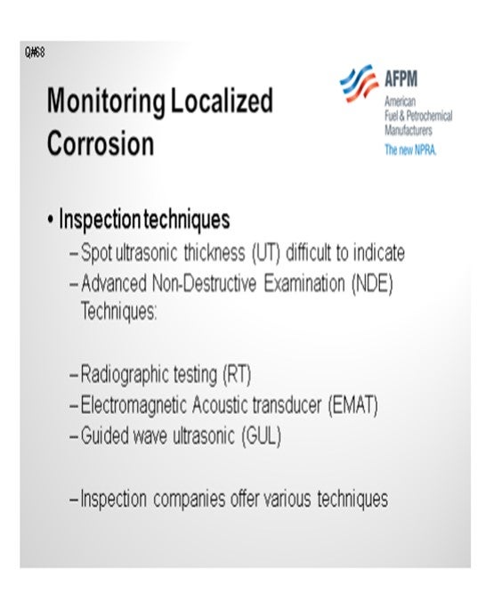
There are companies that offer online monitoring, which consists of field-mounted UT measurements that eliminate the variability of coming back six months later and getting the exact spot that you tested ultrasonically before. Hydrogen permeation plates, for example, detect the byproducts of corrosion, but all of these online programs are installed at fixed locations. They will not detect if the conditions upstream or downstream have changed and have thus moved the localized corrosion to an area outside of where you are monitoring. So, it is important to understand your overhead corrosion program and stay within your safe operating windows.
LEE (BP North America)
Online continuous chloride analyzers are now available in CDU overhead water service. We touched on it earlier. We have a couple of installations at BP refineries. This device provides a good view of the blips and excursions in the operating timeline where much of the corrosion damage can occur in a relatively short period of time. It also provides a means of being informed on operator adjustments and neutralizer addition that may occur between shifts and which might otherwise not be apparent when a spot reading is taken only every two or three days. Additionally, some of our sites have had good experience with the permanently mounted UT probes. We use the Permasense® wireless probes, like those that Steve mentioned. Readings can be taken as frequently as you want. Accuracy can be good, although sometimes we have had problems with the probes showing apparent growth and thickness.
DION (GE Water & Process Technologies)
GE developed a nonintrusive UT device through their Sensing & Inspection Technologies division. It is called GE Rightrax*. It is chain-mounted on the pipe with a temperature ceiling of 662°F around a pipe diameter of up to 42 inches. It can be strapped onto a pipe and relocated as desired.
CLIFFORD (Motiva Enterprises LLC)
There are two aspects to this answer. The first is around predicting where corrosion may occur, and then the actual inspection techniques used to look for it. In general, maintaining high temperatures in atmospheric tower overheads is the preferred method for preventing corrosion because maintaining temperatures well above salt points and dew points is important. However, this question appears to be related to corrosion which is occurring downstream of the primary condensers, past where dew points or salt points are expected to occur. As will be discussed further in question 2003, it is possible to predict salt point and water dew point. With respect to that question, the concern is around the increase of the salt point relative to operating conditions and corrosion control. That phenomenon will result in fouling and corrosion at higher temperatures than anticipated. Those same techniques can be used to determine the effect on water dew points and waterwashes by increasing temperatures and/or process flow rates in those areas. In columns that have overhead waterwashes, increasing temperatures and/or rates, may result in an insufficient amount of liquid water remaining at the point of injection. This will result in localized conditions of high corrosivity as the injected water phase may evaporate leaving wet corrosive salts in its place. In cases where waterwash is not used, the increased temperature and material may shift the water dew point downstream of the design location. This will result in localized conditions until a sufficient amount of water is condensed. These localized conditions are very difficult to predict and spot ultrasonic thickness may not accurately represent the actual corrosion of the overhead system. Alternate methods which may provide more information than a spot UT include radiographic testing (RT), electromagnetic acoustic transducer (EMAT), or guided wave ultrasonic technology (GUL) to look for localized thinned areas. Many inspection companies and vendors will offer similar services.
If you do find a localized thinned area, there are methods to monitor these areas online. One technology allows for field mounting of UT thickness monitoring devices. In this fashion the variability of field UT measurements can be minimized. Another technique which can be employed involves hydrogen permeation plates. These plates detect the presence of hydrogen which is a byproduct of the corrosion reaction. While not a measurement of metal loss, it can measure if corrosion is occurring and based on conditions and rates, the rate of corrosion can be estimated.
DION (GE Water & Process Technologies)
Multiphase piping systems such as crude overhead systems often experience localized flow-enhanced corrosion/erosion effects and it is necessary to monitor these rates at critical locations (e.g., water drop out zones, slugging areas, bends and other positions that cause turbulence within the pipe). However, obtaining quality corrosion data in these areas frequently enough to adequately predict equipment failure can be difficult and/or costly (e.g., manpower, scaffolding, etc.). The ability to quickly and easily gather piping thickness data remotely allows for greater understanding of the system’s corrosion dynamics and better prediction of equipment failure timing. Traditionally, monitoring of corrosion and erosion or any other material loss process involves manually scanning pipe work, vessels and pipelines with an ultrasonic probe by a skilled operator. Additionally, high costs may be incurred due to the necessity of removing insulation, erecting scaffolding, shutting down equipment, and other complicated logistics to allow access to the area of interest. Several manufacturers supply nonintrusive online UT measurement systems that provide high-quality thickness data without the need to interrupt equipment integrity. The GE Sensing & Inspection Technologies division has developed an online UT measurement device called Rightrax* HT that can detect piping metal losses through a nonintrusive monitoring system that provides a direct measurement of localized material loss. The UT sensors are held in place on the pipe exterior using a chain-mounting coupling which requires no welding or penetration of the pipe and measures the actual wall thickness with sound waves instead of correlating voltage differences, as in traditional corrosion probe technology. The result is a repeatable wall thickness measurement, with measurement accuracy of 0.1 mils on piping up to 42-inches in diameter and temperatures up to 662°F. Additionally, the unique mounting technology of the Rightrax* system allows for the adjustment or movement of the monitoring system when necessary to accurately monitor corrosion activity as needed.
The selection of the appropriate location and orientation of the monitoring sensor is critical to the success of the monitoring process. The advantage over portable handheld devices is remote monitoring. Once these online UT systems are correctly installed at the appropriate location, there is no need to revisit the site and, subsequently, eliminates the need to send operators into hazardous environments or remote locations to measure wall thickness.
LEE (BP Products North America)
Online continuous chloride analyzers are now available in CDU overhead water service. We have a couple of installations at BP refineries. This device provides a good view of blips and excursions in the operating timeline, where much of the corrosion damage can occur in a relatively short time period. It also provides a means of being informed on operator adjustments in neutralizer addition that may occur between shifts, and which are not otherwise apparent when only a spot reading is taken every day or few days.
Additionally, some of our sites have had good experience with the permanently mounted Permasense® UT probes. These are the wireless probes and Permasense is the vendor. Readings can be taken as frequently as wanted. Accuracy can be good, although sometimes we have problems with the probes showing apparent growth in thickness.
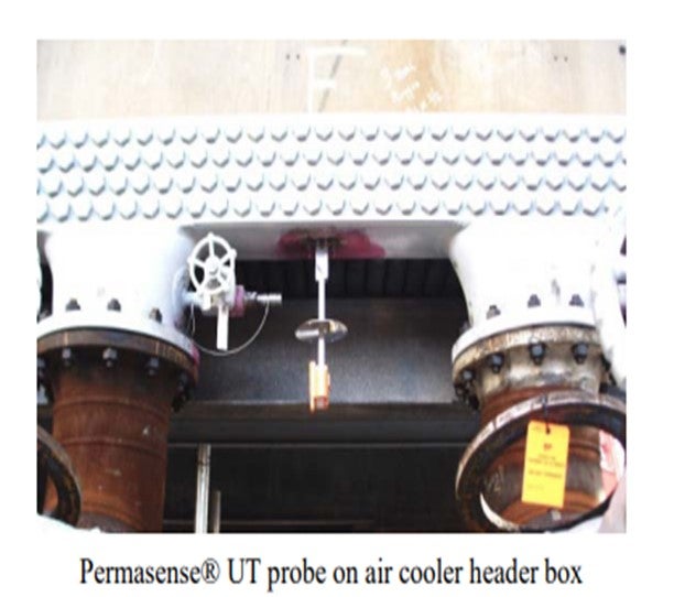
RANDY RECHTIEN (Baker Hughes)
To properly monitor corrosion in tower overhead systems, multiple techniques should be employed. Relying on a single method is insufficient to provide a complete picture of overall corrosion risk. In addition to traditional metal loss techniques (e.g., UT and ER probes), the use of hydrogen permeation measurement has proven successful in monitoring corrosion activity, particularly in localized areas.
Frequent analyses of overhead drum waters must also be performed to capture variations in contaminant levels. Recent improvements in online analytical equipment allow for nearly “real-time” feedback on variations in pH, chloride and iron levels in the drum water. The measured values from these analyzers can then be used to frequently and properly adjust treatment additives to improve corrosion control. Combining the output from these techniques with Baker Hughes’ TOPGUARD™ Corrosion Monitor ensures that corrosion control programs are performing as desired.
DENNIS HAYNES (Nalco Energy Services)
A new piece of equipment used for looking at overhead systems has been designed by Nalco that combines other components with an automatic analysis for iron content in overhead condensate analysis to be able to evaluate changing trends in overhead systems. A company called Permasense® also has developed an online UT device for measuring corrosion and evaluating rate changes for process equipment.
Year
2012
Process