


Question 2: We have a Selective Hydrogeneration Units (SHU) unit that removes butadiene from the olefin feed to the alkylation unit. What is the typical concentration of hydrogen and light ends in the olefin product leaving the SHU? How do hydrogen and light ends affect alky operations?
THOMAS PORRITT (Chevron U.S.A)
A selective hydrogenation unit or SHU converts diolefins to olefins in a stream before it feeds an alkylation unit.
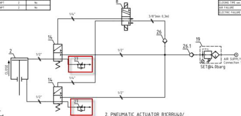
Below is a basic flow scheme.

Figure Q2 - 1 Selective Hydrogenation Unit Flow Scheme
The typical composition of non-condensable gases and light hydrocarbons leaving the SHU is dependent upon both the feed and the hydrogen make up. The olefin feed may contain methane, ethane and ethylene in addition to the olefins and diolefins that pass through the reactor. The hydrogen composition can contain a mixture of light hydrocarbons as well as carbon monoxide and carbon dioxide depending on the source. A component balance on these contaminants can show their concentrations in the SHU effluent for the user’s system.
Hydrogen sources vary by nature and quality. Hydrogen produced by a Steam Methane Reformer, SMR, with a pressure swing adsorption, PSA, unit will be the cleanest. PSA units can produce hydrogen that is greater than 99% pure. Not all SMR hydrogen is purified by a PSA. For SMR hydrogen that passes through methanation and chemical absorption, the hydrogen can contain methane and possibly carbon dioxide. At the other end of the spectrum is naphtha reformer hydrogen. This hydrogen can be as low as 70% hydrogen by volume. Reformer hydrogen can contain as much as 8% methane and 6% ethane by volume. The amount of carbon monoxide is dependent on the system pressure of the naphtha reformer. Low-pressure units can produce hydrogen with as much as 30 ppmv carbon monoxide. Excess hydrogen in the SHU leads to oversaturation of the olefins feeding the alkylation unit. In addition, it leads to increased reactor differential temperature and can potentially damage the palladium catalyst in the reactor beds.
The light hydrocarbons and non-condensable gases exiting the SHU pass to the alkylation unit. They then build up and lead to increased pressure in the refrigeration loop. Because they do not condense, they reduce the capacity of the refrigerant compressor and condenser. To manage pressure, the user is forced to vent the non-condensable gases at the refrigerant accumulator. Unfortunately, this venting also leads to loss of iso-butane.
To mitigate these issues the user can proactively clean up the light hydrocarbons in the FCC olefins and better purify the makeup hydrogen. In addition, the user can adjust the hydrogen to olefin ratio by improving control of hydrogen to the SHU. As a final step, the user can vent the gasses at the refrigerant accumulator.
McDermott-Lummus Technology and Dupont Clean Technologies both contributed to this answer.
BILL KOSTKA (Axens North America)
The unreacted hydrogen in the effluent of a Selective Hydrogenation Reactor is very low, typically within the range of 20-50 ppmw.
Methane in the effluent of a Selective Hydrogenation Reactor comes directly from the hydrogen make-up and thus depends on its quality. For PSA hydrogen, the typical amount of residual methane in the reactor effluent is less than 10 ppmw. For a hydrogen-rich stream containing 90 mole% hydrogen and 10 mole% methane, the methane content rises up to typically 500-1,000 ppmw in the reactor effluent.
In a Sulfuric Acid Alkylation unit, ethane and lighter may cause venting from the refrigeration receiver if levels are high. The vent would carry some isobutane, but no sulfuric acid, and would typically go to the flare. A small, packed scrubber may be needed to remove SO2 if venting is done on a continuous basis. Pentanes in the feed cause no operational problems since they will end up in the alkylate product. However, they could result in difficulty meeting RVP and octane targets if these are critical.
RICK DENNE (Norton Engineering Consultants, Inc.)
A typical design would include a downstream stripper or de-ethanizer column to remove excess hydrogen and light ends to the plant fuel gas system. The column would operate in such a manner that propylene/propane loss are minimized, so as to not downgrade their value. Ethane and lighter streams would be rejected. If fractionation is poor, the stream could be routed to the plant’s sat gas unit; however, care must be taken to avoid putting the liquid propane product off test for excessive propylene. If a stripper or de-ethanizer column is absent, the light ends will act as a diluent in the alkylation unit and the non-condensables will cause pressure issues in various parts of the unit. In this case, the owner/operator should weigh the option of minimizing hydrogen to the SHU, at the expense of more rapid catalyst deactivation, versus alkylation unit limits. Improved make-up hydrogen quality should also be considered.
Year
2019
Submitter
Process
Question 3: What is your experience with ball valves in feed and make-up gas drier circuits in ISOM Units? What strategies have you adopted for monitoring leaks, regular maintenance and achieving longer run length?
DAVINDER MITTAL (HPCL Mittal Energy)
The gas and liquid dryers perform important task of safeguarding the ISOM catalyst from water vapor and other impurities in the make-up hydrogen and hydrocarbon feed.
The dryer switching valves play an important role of directing the inlet/outlet gas streams into the adsorption beds, switching the dryers from adsorption phase to regeneration phase (and cooling phase) and vice versa in a pre-set sequence.
The switching or sequencing valves generally operate under hot regeneration conditions with temperature up to 200 – 350oC, temperature swings up to 25 – 350oC and some particulate (molecular dust) environment with an operating pressure up to 30 – 45 bar. The valves are usually tight shutoff, typically metal seated class-V for feed dryer valves and metal seated class V or VI for hydrogen dryer valves. The switching valves performance is critical for optimum dryer operation and therefore the whole process success.
The internal leakage of ball valves in Isomerization dryer circuits may have various consequences such as pressurization of dryer regeneration section and ineffective regeneration due to wet gas/liquid leak to low pressure regeneration side. Moreover, the cyclic operation of the valves in hot, abrasive service can create high maintenance costs.
The issues of internal leakage have been observed in dryer valves over a period of time mainly due to wear and tear during operation, bumpy operation, slippage of particulate/adsorbent with process stream, wrong selection/ design of valves, non-optimum stroke speed and frequent switch operation specially close to end of run of the dryer adsorbent leading to decrease in service life of valve(s).
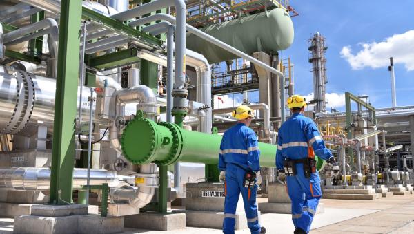
A typical case of incorrect selection of coating material for seat and ball in feed dryer service (API 598-2009) has been experienced. All the installed valves started leaking after about 6 months of installation. The offline testing with both air and water concluded heavy passing of valves. Small adsorbent material was observed on seat cavity, seat grooves, body cavity, trunnion bearings and flow ports. Heavy scratches were found on valve seat. The scratches were found on ball surface also but relatively less deeper and severe. The scratches created a clearance space between seat and ball resulting in valve leakage.
Picture-1: particulate matter on valve seat and ball
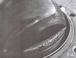
Picture-2: Scratches on valve ball
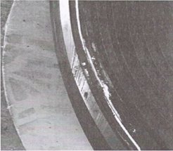
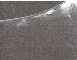
Picture-3: Scratches valve seat
The liquid hydrocarbon samples from Feed dryers indicated adsorbent material slippage from the bed. Feed dryers were opened for adsorbent replacement coinciding with a planned downtime and the molecular sieve bed was found to be significantly disturbed with lateral mixing of inert balls and adsorbent (cylindrical extrudates).
The root cause analysis recommended change in coating material for seat and ball in commensurate with dryer service application besides aligning SOPs to avoid bumpy operations and review the valve opening/closing stroke times and profiles according to the process needs by adjustment in pneumatic circuits.
The coating of the seat was changed from SS stellite (hardness: 400 vickers) to chromium carbide (CrC) and that for ball from NiBo (Nickel – Boron, hardness: 600 vickers) to chromium carbide (CrC, hardness: 800 vickers).
The stroke speed of valves was reduced by adding check valve on actuator pneumatic circuit. Check valves were added in air operated valve exhaust ports to optimize stroke speed from 10 -15 sec to 40-50 sec for full travel.
Picture-4: check valve added in pneumatic circuit (red highlighted).
With durable two-way tightness with hard coating ensures a long-lasting tightness in demanding applications with variable temperature and other process conditions.
Subsequent to implementation of above recommendations, no noticeable leakage has been observed till date.
Further, it is important to establish a protocol for periodic leak check of switch valves during normal operation and complete one cycle for all switch valves within a specified period (say 6 months). The repair of the leaky valves can be done progressively during idle time (standby time) of dryer or while continuing the process using manual isolation valves with proper safety.
Leak check point
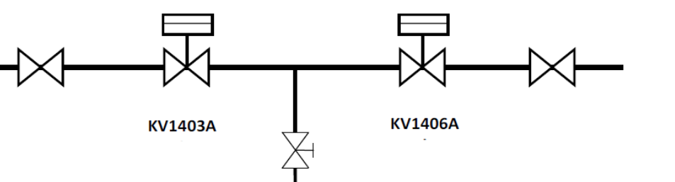
Picture-5: Typical switch valve arrangement
If it is required to estimate quantum of leak, following set up may be adopted.

If there are signs of significant decrease in regeneration efficiency or frequent instances of pressurization of regeneration section during normal operation, it is important to plan leak test and repair of faulty switch valves at the earliest.
Besides above, it is usually a good practice to perform leak test of dryer circuit valves as a whole during planned downtime (if time permits) for quick verification of leak status.
During such leak test, the leak is identified for the set of dryers as whole (say Dryer A to B and Dryer B to A) with one dryer in pressurized condition with hydrogen and other in depressurized condition. If the fall or rise in pressure of individual dryer is within 0.05 Kg/cm2 per hour for 4 consecutive hours (may vary depending upon Licensor guidelines), it confirms that switching valves are tight enough.
If the leak test as above is not proved to be successful (pressure change more than 0.05 Kg/cm2 per hour), the next step is to identify the specific switch valves which may be leaking. This situation should be rare with above mentioned practices in place.
With regard to maintenance, it may be good to keep at least one set of spare seat and ball for each size along with common pneumatic circuit spares and facility for lapping, hydrotest in local workshop.
Additionally, in our case, as part of asset performance management, pneumatic circuit leaks and abnormalities are checked in weekly rounds through hand held smart device configured with alerts for any deviation from normal condition.
During pre-commissioning stage of unit, the cleaning of feed and dryer circuit pipelines is of paramount importance to avoid leak in the switch valves at a later stage. Also, the protection of switch valves after arrival at site is equally critical to avoid internal leaks during operation.
The particle diameter of adsorbent/inert supporting balls and loading pattern in the dryer requires particular attention to avoid slippage of particulate matter from the outlet collector/Feed diffuser during adsorption/regeneration phase. The SOPs should be aligned to avoid jerky operation and eliminate possibilities of disturbance of adsorbent bed.
BILL KOSTKA (AXENS NORTH AMERICA)
Isom valves in feed and make-up gas drier circuits need to be able to resist hot regeneration gas (200-350 °C) and temperature swings (25-350 °C). Operability needs to continue even In the presence of occasional particulates originating from the drier material with an operating pressure up to 50-60 bar. Tight shutoff necessitates class V valves for feed drier circuits and class V or VI valves for hydrogen make-up gas drier circuits.
API standard 598 covers testing and inspection requirements for valves. It specifies acceptable leakage rates for liquid and gas testing. All valves utilized in Isom drier service are built to the various API standards and are required to meet API-598 leakage criteria prior to shipment from the manufacturer or supplier. The Isom customer typically selects a valve type that meet the standards specified by the Isom vendor for the required service and is within their experience band.
Ball valves have been used for both feed and hydrogen driers. Some clients have experienced leaks during startup with this type of valve. These clients typically mange this issue on their own.
RICK DENNE (Norton Engineering Consultants, Inc.)
For monitoring valve passing, temperature monitoring has shown to be adequate in identifying suspected leakers. Routing checks, weekly, by unit operating personnel should be done to establish a baseline for what typical temperatures are. The frequent opening and closing of the valves combined with the varying of temperature makes this service challenging. One way to maximize run lengths is to minimize the frequency of the drier regenerations. To achieve this, consider installation of a caustic system for sulfur removal and a chiller system to reduce saturated moisture content. By adding these processes, the molsieve drier demands are minimized to only final saturation level moisture removal.
Year
2019
Submitter
Process
Question 4: What are your best practices for controlling caustic strength in an isomerization unit scrubber? How frequently is the caustic refreshed?
DAVINDER MITTAL (HPCL Mittal Energy)
There are some other related important factors for controlling and maintaining caustic strength like:
• PERC injection in feed
• Wash water tray integrity
• Stabilizer off gas quality
• Scrubber skimming
• Operational load
• Quality of packing
• Contaminants
• Fresh caustic batch preparation and analysis
PERC Injection in feed: It is quite important to optimize PERC injection in feed as guided by technology supplier as otherwise the HCl concentration in off gas can go too high (normal range 1500 - 2500 ppm). This will lead to rapid depletion of caustic strength due to neutralization effect, thereby requiring frequent fresh caustic make-up.
Wash water tray integrity: The wash water tray in scrubber column also significantly impacts caustic strength in the column. If the tray is heavily leaking due to mal-operation or mechanical fault, the water leakage from the tray to scrubber bottom will lead to loss of caustic strength very rapidly (due to dilution), requiring frequent caustic make-up. Hence, it’s important to ensure on regular basis that that scrubber chimney tray is operating well and is leak proof.
Stabilizer Off gas quality: The hard re-boiling stabilizer can lead to slip of higher hydrocarbons (C5+) in off gas leading to some condensation despite higher caustic temperature. This may lead to foaming and loss of caustic along with off gas.
Scrubber skimming: The scrubber bottom skimming on regular basis will remove top caustic layer laden with some light oil and avoid foaming and loss of caustic due to entrainment. This will be reflected in high pressure drop across scrubber and increase of pH of wash water (> 8.5). The impact can be minimized by regular skimming at least once a week.
Scrubber gas/liquid load: The actual gas/liquid load if higher than hydraulic capability of scrubber, will lead to loss of caustic due to entrainment and will be reflected in high pressure drop across scrubber and increase of pH of wash water (> 8.5).
Scrubber internal condition: The poor quality of raschig rings due to too high ash content (Ash: 0.5% max, Carbon: 99.5% min, mechanical strength > 650 Kg/m2) and dilution of ashes in presence of caustic may lead to damage of carbon raschig rings resulting in high pressure drop across scrubber and loss of caustic due to entrainment.
Contaminants: Normally, aqueous caustic do not possess any contaminants that impacts ISOM scrubber operation. However, if the caustic is already polluted with acidic components (such as H2S or HCl), it will have detrimental impact on alkalinity of the caustic solution. This shall impact overall neutralization effect of the caustic solution during normal operation and reduction in caustic strength will be observed more frequently requiring fresh caustic make-ups.
It is quite important to follow fresh caustic strength and develop necessary guidelines for preparing batch to avoid over dilution or higher strength than required. We are following UOP-209 method for caustic strength analysis.
During changeover of caustic, it is important to perform detection tube analysis for HCl at top of scrubber (normally less than 0.1 ppmv) at the beginning to ensure no HCl slippage.
RICK DENNE (Norton Engineering Consultants, Inc.)
Tight control and monitoring of the chloride injection is key to scrubber performance. The dosing should be monitored and recorded by both the draw-down glass on each operating shift and by tank level on a weekly basis the unit engineer. Over-injecting of chloride will result in faster caustic spending. The scrubber’s outlet gas stream should be monitored and recorded for HCL content via a hand detection tube each operating shift as well.
Year
2019
Submitter
Process
Question 5: How will Tier 3 rules impact gasoline-producing units at your facility?
ABIGAIL SLATER (HollyFrontier)
The Tier 3 gasoline regulation partially took effect in 2017 and will be fully implemented in 2020. The Tier 3 gasoline regulation has impacted the refining industry in a myriad of ways as refiners reduce sulfur further. These impacts will be similar to most refineries, but will have varying severities based on refinery configuration, company compliance strategy, and market factors.
Most facilities reduce the overall gasoline pool sulfur by using Fluid Catalytic Cracking (FCC) Gasoline Hydrotreaters. The primary negative effect from increasing severity on FCC Gasoline Hydrotreaters is the reduction of FCC gasoline octane. It also impacts utility and unit cost of operations. The reduction of FCC gasoline octane impacts the octane balance on the refinery as a whole. This can be addressed in various ways. For example, increased Naphtha Reforming rate and severity, adjusting the sales of Premium Gasoline, adjusting the production and/or purchase of low octane gasoline blend stocks, or generating capital projects to increase the refinery octane balance are all ways to combat the reduction in FCC gasoline octane.
Another potential option to address the new sulfur constraint is to reduce the volume and/or concentration of high sulfur FCC gasoline. This can be done by adjusting FCC operation. Adjusting conversion (less FCC gasoline production), catalyst formulation, or fractionation (to lower gasoline distillation end point) can lower the FCC gasoline volume and/or sulfur concentration. By reducing the percentage of FCC gasoline in the overall pool, the overall sulfur is reduced. FCC catalyst vendors also have additives that can partition the sulfur from the gasoline to dry gas.
The strategies employed by each refinery will be different. There is not a “one size fits all” to solving the Tier 3 gasoline regulation. With that being said, the biggest issues to resolve will be to reduce sulfur while still maintaining the overall octane in the gasoline pool.
THOMAS PORRITT (Chevron U.S.A.) (2)
Managing feed sulfur for the FCC is a critical component of meeting Tier 3 specifications. FCC rates will depend on availability of internally produced and purchased low sulfur feed. Other higher-sulfur gasoline blend components will need outlets such as hydrotreating or mixing into export blends.
RICK DENNE (Norton Engineering Consultants, Inc.)
Many refiners are finding that with tier 3 the alkylate stream is now one of the larger contributors to the gasoline pool sulfur. For HF alkylation units, minimizing feed sulfur content has always been important for unit acid consumption. Now, the impact of feed sulfur to the alkylate product is of concern to the gasoline blender. Tight feed pre-treatment for sulfur is becoming more critical. For sulfuric acid alkylation units, an alumina bed treater either on the unit alkylate product stream or in place of the net effluent treatment section is an option to reduce product sulfur.
Refiners that have the FCC and Alkylation units on different turnaround schedules will find it very challenging to blending the butane/butylene stream if the sulfur treatment section is located within the battery limits of the Alkylation unit. Provisions must be made to keep the treatment section in service or find a means to store the higher sulfur butane/butylene stream during an Alkylation unit outage.
GEORGE HOEKSTRA (Hoekstra Trading LLC)
We have field test data from 12 commercial FCC gasoline desulfurizers that show higher octane loss than has been anticipated by the industry when making Tier 3 gasoline. The incremental octane loss when moving from Tier 2 to Tier 3 will likely be five times higher than was anticipated when the Tier 3 standard was enacted. None of the 12 commercial units in our field test data base indicates octane loss as low as that anticipated when the standard was enacted.
The octane will be lost when severity is increased in gasoline desulfurizers to lower the sulfur of FCC gasoline. In addition to octane loss, a lower product sulfur specification introduces new constraints on kinetic capacity, hydrogen availability, splitter effectiveness, feed flexibility, cycle life, synchronization of unit downtime, and processing of orphan streams requiring desulfurization. These constraints will surely come into play, especially in refineries that don’t have FCC pretreaters and those with gasoline desulfurizers not designed for Tier 3 service.
The biggest cost factor for Tier 3 is replacement of the octane lost in gasoline desulfurizers. This will be mostly done by increasing alkylate or higher-octane reformate in gasoline blends, which comes at a cost, and with capacity limits that depend on the refinery and feed. Some refineries are already paying $millions/month to replace lost octane with purchased alkylate.
When facing octane constraints, refiners can also reduce their production of premium gasoline and/or export non-compliant gasoline. But these remedies can really hurt profits because the retail value of octane in the US has tripled in recent years, making octane barrels an increasingly valuable commodity in the US market:
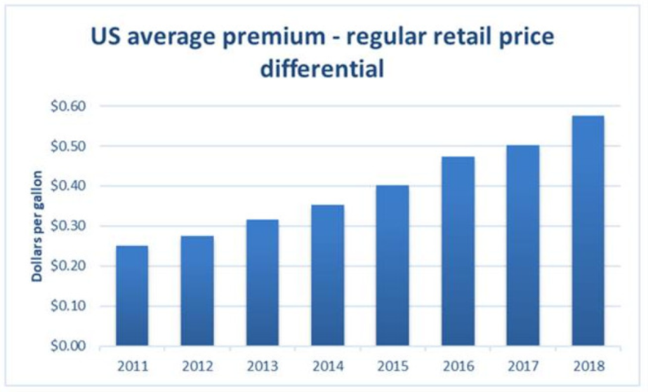
Most US refineries have never made Tier 3 gasoline in substantial volume. Now, with the issue urgent, many unknowns must be worked out in real time. The costs and benefits will be widely distributed across US refiners.
Our pilot plant and field test studies have led to development of new tools and methods to reduce octane loss in gasoline desulfurizers which can be implemented immediately with no capital investment. These optimization tools, and all the data on which they are based, are available to anyone at negligible cost through Hoekstra Trading.
Year
2019
Submitter
Process
Question 6: What is your main blending limit for gasoline for both summer and winter specs?
ABIGAIL SLATER (HollyFrontier)
Gasoline blending specifications are vast and different in various geographical areas. The common blending limit that taxes both summer and winter specifications are volatility specifications. Depending on the gasoline blend, Reid Vapor Pressure (RVP), Total vapor over liquid (TV/L), and distillation (typically T10 and T50) can be limiting in both seasons.
We see that RVP is typically more limiting in the summer season. This can be managed by butane blending. Some refineries will store or sell butane during the summer and blend butane during the winter. The second biggest limit in the summer is typically T10 of the distillation, as many of the gasoline components in the blend are heavier due to the lower RVP limit.
Additionally, TV/L is more limiting in the winter season. As refineries attempt to take advantage of the higher RVP limit during the winter, the TV/L limit will generally be reached prior to reaching the RVP limit. The second biggest limit in winter is typically T50, as many of the gasoline components in the blend are lighter to take advantage of the higher RVP limit.
Other limits that occur during both seasons are octane and benzene limits. Octane must be managed by the refiner’s overall octane pool. This can be done by manipulating octane producing units within the refinery (Naphtha Reforming, Isomerization, Alkylation, etc.). Benzene limits are sometimes present and can be reduced by benzene saturation units and proper naphtha splitting (for example, ensuring benzene pre-cursors stay out of dehydrogenating units such as Naphtha Reformers).
Gasoline limits can be impacted by crude slate, refinery configuration, fractionation efficiency, and desired product slate. As gasoline specifications change with Tier 3, NAAQS, increased ethanol blending, etc. and more pressure is put on the gasoline blends, then the limits can shift between the different volatility specs.
THOMAS PORRITT (Chevron U.S.A.) (2)
Summer: RVP typically managed by butane blending
Winter: Total vapor over liquid (TV/L) & minimum distillation in winter, also managed by butane blending
Year
2019
Submitter
Process