Question 3: What is your experience with ball valves in feed and make-up gas drier circuits in ISOM Units? What strategies have you adopted for monitoring leaks, regular maintenance and achieving longer run length?
DAVINDER MITTAL (HPCL Mittal Energy)
The gas and liquid dryers perform important task of safeguarding the ISOM catalyst from water vapor and other impurities in the make-up hydrogen and hydrocarbon feed.
The dryer switching valves play an important role of directing the inlet/outlet gas streams into the adsorption beds, switching the dryers from adsorption phase to regeneration phase (and cooling phase) and vice versa in a pre-set sequence.
The switching or sequencing valves generally operate under hot regeneration conditions with temperature up to 200 – 350oC, temperature swings up to 25 – 350oC and some particulate (molecular dust) environment with an operating pressure up to 30 – 45 bar. The valves are usually tight shutoff, typically metal seated class-V for feed dryer valves and metal seated class V or VI for hydrogen dryer valves. The switching valves performance is critical for optimum dryer operation and therefore the whole process success.
The internal leakage of ball valves in Isomerization dryer circuits may have various consequences such as pressurization of dryer regeneration section and ineffective regeneration due to wet gas/liquid leak to low pressure regeneration side. Moreover, the cyclic operation of the valves in hot, abrasive service can create high maintenance costs.
The issues of internal leakage have been observed in dryer valves over a period of time mainly due to wear and tear during operation, bumpy operation, slippage of particulate/adsorbent with process stream, wrong selection/ design of valves, non-optimum stroke speed and frequent switch operation specially close to end of run of the dryer adsorbent leading to decrease in service life of valve(s).
A typical case of incorrect selection of coating material for seat and ball in feed dryer service (API 598-2009) has been experienced. All the installed valves started leaking after about 6 months of installation. The offline testing with both air and water concluded heavy passing of valves. Small adsorbent material was observed on seat cavity, seat grooves, body cavity, trunnion bearings and flow ports. Heavy scratches were found on valve seat. The scratches were found on ball surface also but relatively less deeper and severe. The scratches created a clearance space between seat and ball resulting in valve leakage.
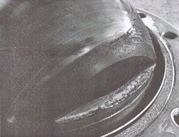
Picture-1: particulate matter on valve seat and ball
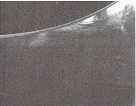
Picture-2: Scratches on valve ball
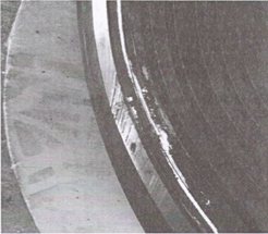
Picture-3: Scratches valve seat
The liquid hydrocarbon samples from Feed dryers indicated adsorbent material slippage from the bed. Feed dryers were opened for adsorbent replacement coinciding with a planned downtime and the molecular sieve bed was found to be significantly disturbed with lateral mixing of inert balls and adsorbent (cylindrical extrudates).
The root cause analysis recommended change in coating material for seat and ball in commensurate with dryer service application besides aligning SOPs to avoid bumpy operations and review the valve opening/closing stroke times and profiles according to the process needs by adjustment in pneumatic circuits.
The coating of the seat was changed from SS stellite (hardness: 400 vickers) to chromium carbide (CrC) and that for ball from NiBo (Nickel – Boron, hardness: 600 vickers) to chromium carbide (CrC, hardness: 800 vickers).
The stroke speed of valves was reduced by adding check valve on actuator pneumatic circuit. Check valves were added in air operated valve exhaust ports to optimize stroke speed from 10 -15 sec to 40-50 sec for full travel.
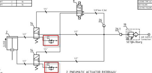
Picture-4: check valve added in pneumatic circuit (red highlighted).
With durable two-way tightness with hard coating ensures a long-lasting tightness in demanding applications with variable temperature and other process conditions.
Subsequent to implementation of above recommendations, no noticeable leakage has been observed till date.
Further, it is important to establish a protocol for periodic leak check of switch valves during normal operation and complete one cycle for all switch valves within a specified period (say 6 months). The repair of the leaky valves can be done progressively during idle time (standby time) of dryer or while continuing the process using manual isolation valves with proper safety.
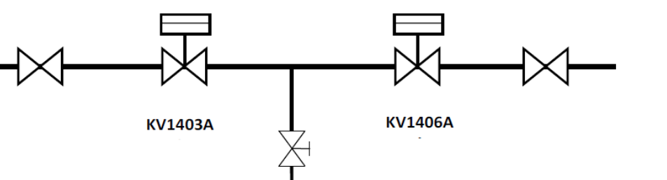
Leak check point
Picture-5: Typical switch valve arrangement
If it is required to estimate quantum of leak, following set up may be adopted.

If there are signs of significant decrease in regeneration efficiency or frequent instances of pressurization of regeneration section during normal operation, it is important to plan leak test and repair of faulty switch valves at the earliest.
Besides above, it is usually a good practice to perform leak test of dryer circuit valves as a whole during planned downtime (if time permits) for quick verification of leak status.
During such leak test, the leak is identified for the set of dryers as whole (say Dryer A to B and Dryer B to A) with one dryer in pressurized condition with hydrogen and other in depressurized condition. If the fall or rise in pressure of individual dryer is within 0.05 Kg/cm2 per hour for 4 consecutive hours (may vary depending upon Licensor guidelines), it confirms that switching valves are tight enough.
If the leak test as above is not proved to be successful (pressure change more than 0.05 Kg/cm2 per hour), the next step is to identify the specific switch valves which may be leaking. This situation should be rare with above mentioned practices in place.
With regard to maintenance, it may be good to keep at least one set of spare seat and ball for each size along with common pneumatic circuit spares and facility for lapping, hydrotest in local workshop.
Additionally, in our case, as part of asset performance management, pneumatic circuit leaks and abnormalities are checked in weekly rounds through hand held smart device configured with alerts for any deviation from normal condition.
During pre-commissioning stage of unit, the cleaning of feed and dryer circuit pipelines is of paramount importance to avoid leak in the switch valves at a later stage. Also, the protection of switch valves after arrival at site is equally critical to avoid internal leaks during operation.
The particle diameter of adsorbent/inert supporting balls and loading pattern in the dryer requires particular attention to avoid slippage of particulate matter from the outlet collector/Feed diffuser during adsorption/regeneration phase. The SOPs should be aligned to avoid jerky operation and eliminate possibilities of disturbance of adsorbent bed.
BILL KOSTKA (AXENS NORTH AMERICA)
Isom valves in feed and make-up gas drier circuits need to be able to resist hot regeneration gas (200-350 °C) and temperature swings (25-350 °C). Operability needs to continue even In the presence of occasional particulates originating from the drier material with an operating pressure up to 50-60 bar. Tight shutoff necessitates class V valves for feed drier circuits and class V or VI valves for hydrogen make-up gas drier circuits.
API standard 598 covers testing and inspection requirements for valves. It specifies acceptable leakage rates for liquid and gas testing. All valves utilized in Isom drier service are built to the various API standards and are required to meet API-598 leakage criteria prior to shipment from the manufacturer or supplier. The Isom customer typically selects a valve type that meet the standards specified by the Isom vendor for the required service and is within their experience band.
Ball valves have been used for both feed and hydrogen driers. Some clients have experienced leaks during startup with this type of valve. These clients typically mange this issue on their own.
RICK DENNE (Norton Engineering Consultants, Inc.)
For monitoring valve passing, temperature monitoring has shown to be adequate in identifying suspected leakers. Routing checks, weekly, by unit operating personnel should be done to establish a baseline for what typical temperatures are. The frequent opening and closing of the valves combined with the varying of temperature makes this service challenging. One way to maximize run lengths is to minimize the frequency of the drier regenerations. To achieve this, consider installation of a caustic system for sulfur removal and a chiller system to reduce saturated moisture content. By adding these processes, the molsieve drier demands are minimized to only final saturation level moisture removal.