


Question 96: What is the CO boiler start-up and shutdown sequence with respect to the FCCU start-up and shutdown timing? What are the reasons for this sequence?
BROOKS (BP Refining)
As I mentioned briefly in an earlier question, most of our FCCs with CO boilers start-up with the CO boilers bypassed. If we run partial-burn on any of these FCCs, we tend to start-up in full-burn at reduced rates. Once the feed is in the unit and considered stable, most sites will cut into their CO boiler with the process flow. Our partial-burn units will then move back into parital-burn. Basically, the CO boilers are started up while the FCC is routed to the bypass stack. As you start up the CO boiler, you fire it initially on fuel gas. Then when the FCC flue gas flow is brought back into the CO boiler, you reduce the fuel gas firing accordingly. We do this in order to prevent running directly through the CO boiler when transitioning from full-burn to partial-burn, which can cause issues with a combustible environment.
Shutdown sequences are similar. We shut down the unit, move all of our partial-burns into full-burns, take flow out of the CO boiler, and then route it to the bypass stack. We have some units that rely on their CO boilers to make steam for the rest of the refinery. Thus, we will go out the bypass sack, isolate it with a blind, and then continue running it online with fuel gas. It is fairly basic, but most of our CO boilers are run that way.
SCHOEPE (Phillips 66)
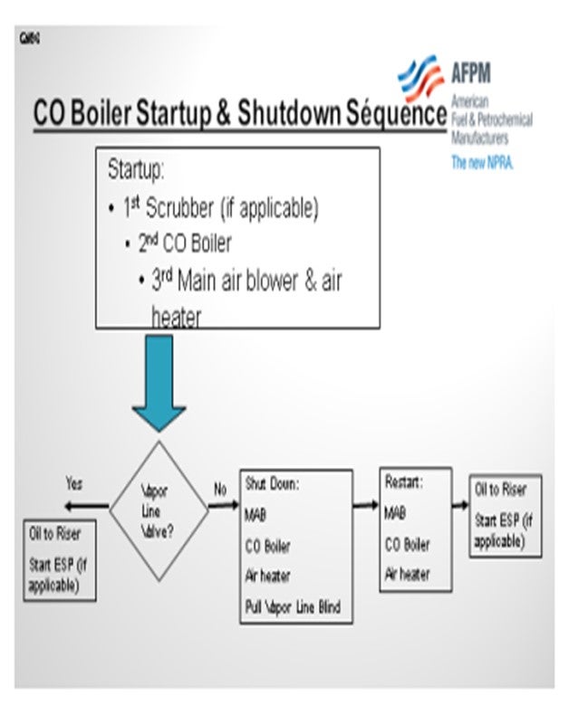
In our units, the CO boiler is one of the first pieces of equipment that is started and one of the last pieces of equipment taken down, unless you have a flue gas scrubber. If you do have a scrubber, you will usually start the scrubber first and then the CO boiler. In some sites, the main air blower partially depends on the steam supply from the CO boiler. We already went through the whole vapor line scenario. If you have a valve, you can then go directly to catalyst loading and oil-in. If not, then shut down all of this equipment, pull the vapor line blind, and start up the equipment again.
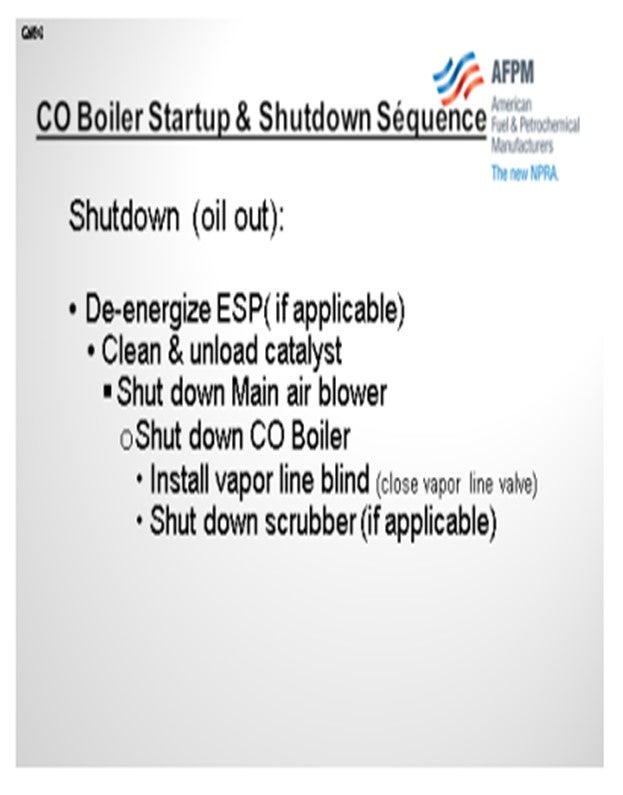
In terms of a shutdown, which is shown on the next slide, our units typically de-energize the ESP first. After that, catalyst is circulated to decoke the catalyst. The catalyst is then unloaded, and the air blower is shut down. Shut down your CO boiler last. That way, you will still be supplying steam to the refinery and your main air blower while minimizing potential CO emission during this catalyst cleanup step.
LALL (UOP, A Honeywell Company)
Although UOP does not dictate when the CO boiler is to be started up on auxiliary firing, our procedure specifies that the FCC is to be started up in complete combustion with flue gas diverted to the bypass stack. The flue gas is diverted to a CO boiler only after the feed has been introduced to the FCC and the regenerator operation has transitioned from complete combustion to stable partial-burn. UOP considers this to be the safest way for the following reasons: 1. There is a minimal chance of the presence of unburned hydrocarbons being in the flue gas as a result of unsuccessful lighting of the torch oil. 2. The feed is routed to the FCC, and the FCC operation and pressure balance is steady. In the event of a pressure upset, there is the potential of a reversal, which could introduce a significant concentration of hydrocarbons into the CO boiler and cause a major upset. 3. The transition from full- to partial-burn is very dynamic and may be unpredictable. UOP’s preference is to not swing from the bypass to the CO boiler during this unstable situation until after feed is introduced to the riser at low rates and after the regeneration has transitioned from full-burn to stable partial-burn. Some refiners may have an ESP or wet gas scrubber downstream of the CO boiler. They must run these whenever feed is in the unit, and they could be forced to run through the CO boiler in this situation; but from a safety perspective, it is not preferred.
PIMENTEL (CITGO Petroleum Corporation)
Our experience is very similar. Our CO boiler start-up and shutdown is relatively independent from the FCC. Actually, we start the CO boiler in advance of the FCC mainly because our air blower turbine requires the steam to run at full capacity. To do this, of course, your boiler must be equipped with an adequate number of auxiliary fuel burners. For the same reason, the FCC shuts down in advance of the CO boiler. The boiler can be kept in operation through the bypass, as was already explained. We shut down later for scheduled work. If there is no work scheduled for the CO boiler during the turnaround, it can continue to run isolated through the entire FCC outage.
MICHAEL LEMESHEV (Zimmerman & Jansen)
At some point, everyone on the panel indicated that during the start-up, you begin to divert some flow into the CO boiler. Is that correct?
BROOKS (BP Refining)
We do not divert any flow to the CO boiler until the FCCU unit is started up.
BROOKS (BP Refining)
BP sites with CO boilers typically start their FCCUs with the CO boilers bypassed. Our partial-burn units will start the unit up in full-burn operation (at reduced feed rates). When feed is in the unit and the unit is considered as stable, sites typically bring the CO boiler into the process flow. Partial-burn units then move from full-burn back to typical partial-burn operations. The CO boiler is typically started up on fuel gas while the FCCU flue gas is routed to the bypass stack. Fuel gas is cut back as the FCC flue gas is routed through the CO boiler. The CO boiler must be fired with fuel gas before the FCC is brought back into partial-burn service in order to avoid an explosion risk. Shutdown sequences are similar. Partial-burn units are brought into full-burn operations (at reduced feed rates) before the CO boiler is taken out of FCC service. Some of our units rely on the CO boiler to provide steam to the refinery. These units typically increase fuel gas firing when the FCCU is routed through the bypass stack on shutdown.
SCHOEPE (Phillips 66)
The start-up sequence is different for units with electrostatic precipitators (ESPs) and units with flue gas scrubbers. Units with ESPs typically start the CO boiler first while units with flue gas scrubbers start the scrubber before the CO boiler is started. Some sites need the steam from the CO boiler to drive the main air blower turbine. After the CO boiler start-up, the main air blower and the in-line air heater are started and the unit is heated for refractory dryout. After refractory dryout, the start-up paths diverge for units with vapor line isolation blinds in comparison to units with vapor line isolation valves.
Units with vapor line isolation blinds steam out the reactor and then shut down the main air blower, the inline air heater, and the CO boiler in preparation for pulling the vapor line isolation blind. After the isolation blind has been pulled, the CO boiler the main air blower and the inline air heater are started up again and the regenerator is heated in preparation for catalyst loading. Units with a vapor line isolation valve simply keep the CO boiler, the main air blower and the in-line air heater running and proceed directly from refractory dryout to catalyst loading.
Just before the introduction of torch oil, the CO boiler combustor temperature is maximized in order to minimize the CO emission during the operation with torch oil.
During shutdown, the CO boiler is usually tripped after catalyst has been unloaded. This way, steam is provided to drive the main air blower and the potential for CO emission is minimized.
PIMENTEL (CITGO Petroleum Corporation)
In our experience, the CO boiler starts up in advance of the FCC, since the air blower turbine depends on the steam from the CO boiler to run at full capacity and the CO boiler is equipped with an adequate number of auxiliary fuel burners. For the same reasons, the boiler is kept in operation (although at a reduced rate) until after the FCC is completely down; exporting steam to the grid and shutting down when required to perform the scheduled maintenance work. If no maintenance work is required, the CO boiler remains in operation during the FCC outage.
LALL (UOP, A Honeywell Company)
Commissioning of the FCCU requires ample steam availability especially for start-ups. In FCCUs equipped with CO boilers, the CO boiler is a major producer of HP steam for the refinery in normal operation. The timing of the CO boiler start-up may be dependent upon the need of the CO boiler to supplement the refinery steam system during start-up of the FCC.
Although UOP does not dictate when the CO boiler is to be started up on auxiliary firing, our procedures specify the FCC is to be started up in complete combustion with the flue gas diverted to the bypass stack. The flue gas is diverted from the bypass stack to the CO boiler only after the feed has been introduced to the FCC and the regenerator operation has transitioned from complete combustion to stable partial-burn mode. UOP considers this to be the safest way as the unit will be stable before the diverter valve is directed to the CO boiler for the following reasons:
a) There is minimum chance for unburned hydrocarbons in the flue gas from unsuccessful lighting off of torch oil.
b) Feed is routed to the FCC riser and the FCC operation and pressure balance is steady - in event of a pressure upset there is the potential of a reversal which could introduce a significant concentration of hydrocarbons into the CO boiler and cause a major upset.
c) The transition from full-burn to partial-burn is very dynamic and may be unpredictable. UOP preference is not to swing from bypass to CO boiler during this unstable situation until after feed is introduced to the riser at low feed rate and the regeneration has transitioned from full-burn to stable partial-burn operation.
Some refiners may have an ESP or wet gas scrubber downstream of CO boiler and must run these whenever feed is in the unit and may be forced to run through the CO boiler in this situation, but it is not preferred from a safety perspective.
If the CO boiler is required to be commissioned in early in the overall FCC start-up sequence to supplement refinery steam production, this will most likely occur before start of the air blower. The CO boiler will be operated on auxiliary firing (refinery gas) at start up with forced draft fans in operation. Start-up will be performed with the electric driven fan, supplying maximum combustion air and the burner(s) at minimum load (when no HP steam is available for the steam turbine users). The steam demand on steam network determines the degree of firing.
The CO boiler can be shut down any time after feed is removed from the unit to ensure any residual CO production from coke combustion is converted unless the CO boiler is required for refinery steam production. The procedure following feed cut out is to open the diverter valve to the bypass stack and reduce burner load till minimum load, then stop the auxiliary firing and burner(s).
Year
2012
Process
Question 97: What equipment do you employ to help eliminate ESP hopper and downcomer plugging with catalyst fines? What additional operating practices are used? What type of level detectors are in use on the ESP hoppers and/or catalyst storage silos? Are there any new level detection technologies that could be applied, perhaps from coke drum measurement detectors?
PIMENTEL (CITGO Petroleum Corporation)
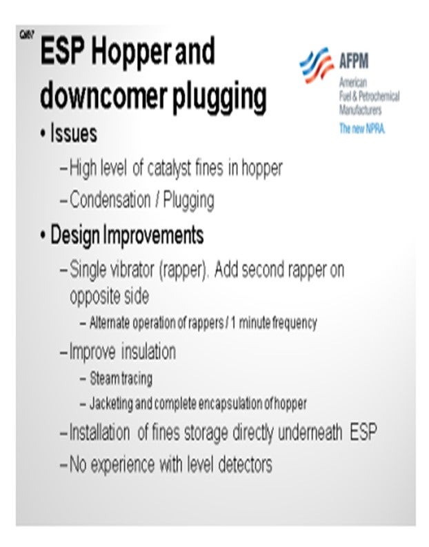
Our main problem with the ESP is fines accumulation in both the ESP hoppers and the transfer line from the hoppers to the fine's storage bin. We have incorporated some design improvements that have helped us minimize, but not completely eliminate, the main problems of condensation in the system and plugging. So, we added a second vibrator or rapper on the opposite side of the hopper, and we run them on alternate cycles of one minute each. The second improvement was to increase insulation of the hopper to a point where we now have it completely encapsulated. We have steam tracing as well. We believe there is still room for improvement.
At this time, we know that we can minimize the run of the piping from the hopper to a storage bin. We are also aware that there is a possibility of actually installing the fines storage directly below the ESP to basically eliminate the problem of plugging the transfer line.
Part of the question asked about our experience with level detectors. We do not have any. We mostly use an infrared gun if we suspect a high level in the hopper.
BROOKS (BP Refining)
BP uses an industry consultant to help us guide our operation on most of our ESPs. This industry consultant has a multitude of experience in ESPs over many years. Because of that, we have similar systems on most of our ESPs and in our ESP hopper systems. We have found that when we target keeping our hoppers warm, we help prevent some of the issues from condensation. Almost all of our hoppers that operate well have electric-traced hoppers to prevent condensation and keep the hoppers warm.
We also focus on trying to keep our hoppers as empty as possible since overfilling causes outages of the TRs (transformer rectifiers). Because of this, some of our sites have a system that continuously empties the hoppers. I do not know a great deal about it, but I am aware that they do this to prevent catalyst fines levels from building up in the hoppers. We have other hoppers that gauge their typical fines generation and develop a schedule of manually emptying their hoppers based on the fines make they expect.
From a level gauge perspective, we use nuclear level gauges on the majority of our units. Again, the same ESP consultant recommends this as the best technology for hopper level indication, and that is why we have employed them at the majority of our sites. A lot of our sites that do not employ these are up against limits for radiation sources on their site, so they are unable to use nuclear level gauges on their ESP hoppers. Those sites have resorted to high-level switches and regular manual dumping of their hoppers. However, these switches can be rather unreliable.
We have also seen issues with the nuclear level gauges. We will sometimes have ledges of catalyst that are sitting over the level gauge making it look like you have a level of catalyst. In those cases, we will back-check our TR operation to determine if we actually have a level or if it is a false indication. We will typically make sure to empty our hoppers more frequently if we feel we have a bad reading on the gauge.
SCHOEPE (Phillips 66)
In our system, ESPs use most of the features that were already mentioned. We make sure that our hoppers are well-insulated and heated and that vibrators are used to keep the hoppers from plugging. Fines are typically dumped on a timed interval, but not so much on level control. However, some of the units do have a gamma ray-type of indicator that can generate a high-level alarm.
PIMENTEL (CITGO Petroleum Corporation)
Our ESP hoppers are equipped with automatic rappers, which create enough vibration to prevent catalyst accumulation. We use a single vibrator on each hopper; hoppers have steam tracing and insulation. We initially had insulation jacketing and then beefed this up with a second layer of insulation that completely encapsulated each hopper. We have also added additional steam tracing on some hoppers. These moves helped to reduce, but not eliminate, the downcomer plugging problem. We think that a second vibrator on each hopper opposite the first hopper would help. We have also increased the vibration frequency in steps so that each hopper vibrator now vibrates once every minute. We have experienced plugging in the transfer line from the hoppers to the catalyst fines storage at times, due to condensation. A good design practice is to minimize the length of the transfer line to the fines storage, or store the fines directly underneath the ESP. We do not have any level detectors in the hoppers (use of I.R. camera when high level is suspected).
BROOKS (BP Refining)
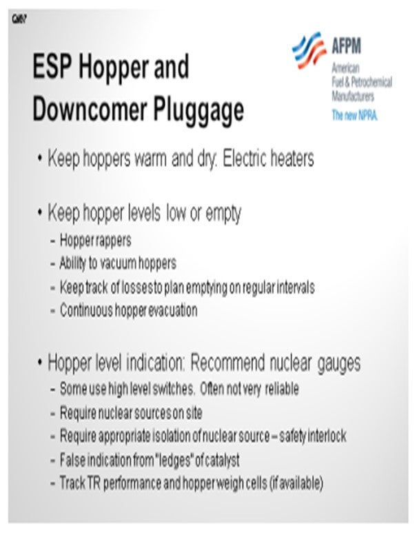
BP uses an industry consultant with a multitude of ESP experience to help guide our ESP operations and optimization efforts. As such, many of our ESPs employ similar systems to manage fines handling. Our hoppers are typically equipped with electric heaters to maintain temperatures. We have found that keeping hoppers warm is one of the biggest keys to prevent pluggage. Warm hoppers prevent liquid condensation from causing fines clumping and sticking to walls. Most ESPs employ hopper rappers and have an ability to vacuum out hoppers if necessary.
Our sites typically work to keep the hoppers as empty as possible to prevent overfilling and outages of the TRs. Some sites have continuously empting hoppers. Others have gauged their typical fines makes and have regularly scheduled times to manually empty hoppers.
The ESP consultant we use recommends nuclear level gauges as a best technology for the hopper levels, thus these are employed at the majority of our sites. These gauges tend to work well; however, the following are key concerns around using nuclear gauges:
• Gauges require nuclear sources onsite. Some of our sites have had to remove these due to restrictions in the amount of nuclear material onsite. These sites have typically resorted to high level switches and regular manual dumping of hoppers. However, these high-level point readings are often not very reliable.
• It is important to note that the nuclear sources need to be appropriately isolated when work is done in the ESP. It is recommended to include this isolation as a safety interlock.
• Some sites have seen “ledges” of catalyst causing false level indication in the hoppers. This phenomenon is not exclusive to the use of nuclear level gauges. Our sites typically handle this by using tracking TR performance and hopper weigh cells if available to determine if hopper levels are actually too high or if the reading is false. If the reading is false, sites will typically resort to manual emptying of hoppers to maintain levels.
As with any type of indication, there can always be issues associated with these level gauges. However, we feel that the nuclear gauges are the best level indication technology available for this service.
SCHOEPE (Phillips 66)
Electrostatic precipitator hoppers are well insulated and use small heaters and vibrators to prevent plugging. Fines are typically dumped on a regular interval, but gamma ray type level indicators are used which can trigger a high-level alarm.
Year
2012
Process
Question 98: What is your experience with the use of ammonia or steam in the FCC flue gas line in order to improve the operation of the ESP? Please comment on system configuration and operational issues
PIMENTEL (CITGO Petroleum Corporation)
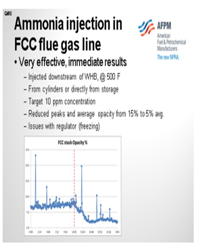
We have extensive experience with the use of ammonia in the FCC flue gas line in order to improve the conductivity of the particles and improve the operation of the ESP. We inject ammonia at the target level of 10 parts per million or less. It is very effective at that concentration and has helped us reduce our baseline opacity level from about 15% to less than 10% or 5%. It also reduced the peaks. The peaks that you see in the chart are related to soot blower operations of the waste heat boiler. Thanks to the ammonia, we now operate the soot blowers more often without the fear of violating the opacity limit. So it is also an energy-saving project.
In our unit, the ammonia is injected directly downstream of the waste heat boiler from cylinders or from a storage tank located outside of the FCC battery limits. The only issue I can recall with this operation has been the loss of ammonia flow due to the regulators plugging with ice. If the ammonia is not completely dry, it will freeze in your regulator. That is easy to fix by putting some steam tracing in the lines. The chart shows typical performance before and after starting the injection of ammonia. As you can see in the chart, it helps us operate the soot blowers more often.
BROOKS (BP Refining)
As Sergio mentioned, the common use for putting in steam and ammonia is to reduce the resistivity of the particulate so it can be picked up easier in the ESP. We do not have a lot of experience with steam helping our ESP operations, apart from the example I mentioned about using steam on start-up before meeting temperatures necessary to use ammonia.
We do have quite a bit of experience with ammonia injection. All of our ammonia injection systems are fairly similar because, again, we use the same consultant for the vast majority of our ESPs. We also found that it is key to focus on your ammonia injection system providing good dispersion in the flue gas stack and good vaporization of your ammonia. Typically, all of our systems include heaters for vaporization and metering injection pumps, so we know how much ammonia we are injecting. The systems also include good dispersion nozzles for the flue gas stacks.
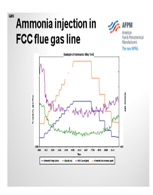
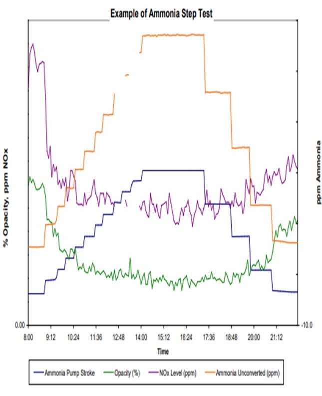
When we use ammonia in our unit, we typically try to optimize it. As shown in the example of an ammonia step test in the slide, the blue and orange lines are essentially the same. They both tell you how much ammonia we are injecting. However, we tend to double-check the meter on the pump stroke versus the actual amount coming in just to make sure we are getting good readings.
You can see that the test includes our stepping up injection rates until we meet a level where we feel like the opacity – the green line – has leveled out. You keep stepping up your ammonia until you believe you have leveled that on opacity, and then you step back down until you feel like your opacity has gone back up. Those are the areas where you would target your ammonia injection rates because you know that is the minimum necessary to maintain your opacity.
I also want to add that I am not sure if other sites have seen instances similar to what we have noticed. Some, but not all, of our sites with ammonia injection into their ESPs also saw a reduction in NOx as a result. It makes sense because you use ammonia in a SNCR (selective non-catalytic reduction) and also in a SCR (selective catalytic reduction) to reduce NOx. However, we do not see it in all of our units.
Those units with high NOx tended to show a good step down and leveling out similar to what we saw with the opacity, which can be seen in the purple line representing NOx. So, you may get an added NOx reduction benefit if you use ammonia on some of your units. We also did the same step test on other units and saw no response to NOx; so, it is not a guarantee.
SCHOEPE (Phillips 66)
I do not have much to add. Halle highlighted all of the points. Phillips 66 has a few installations where we inject ammonia into the ESP. Collection efficiencies were increased by 25% to 50%. It is critical to have good ammonia injection quilts which inject ammonia across the entire duct. Typically, we have not seen any issues with ammonium salt deposition anywhere in the downstream equipment.
MARTIN EVANS (Johnson Matthey Intercat)
To give a contrary comment, I heard a few people talk about the importance of dispersion. We recently had one refiner start ammonia injection and have trouble with the quill. When the quill was removed and the ammonia was injected straight into the nozzle, he got a similar reduction in opacity as he had been getting with the quill. So go figure. It is always the same with the FCC. You can prove something on one unit and then prove the exact opposite in another unit. Another point I want to make is that we have seen that opacity can increase when refiners go to low SOx emissions, typically below 50 ppm and certainly below 20 ppm. This occurs, if you are not using ammonia, because the SO2 (sulfur dioxide) actually acts in the same way as does the ammonia to decrease the resistivity of the catalyst and improve the efficiency of the ESPs. So, when you take out the SO2, you have to replace it with ammonia. Otherwise, you will lose ESP efficiency when you get down to very low SOx levels.
PIMENTEL (CITGO Petroleum Corporation)
We have extensive experience using ammonia in the FCC flue gas line to improve the performance of the ESP. NH3 is a very effective way to improve the conductivity of the flue gas at the levels as low as 10 ppm. In our experience the use of ammonia helped to reduce the flue gas opacity from an average of 15% to less than 5%. Ammonia is injected directly in the flue gas line downstream of the waste heat boiler (at about 500°F) from cylinders or directly from an ammonia storage tank located outside of the unit battery limits. The only operational issue with this system was plugging the regulators with ice, which was solved by steam tracing upstream of the regulator/orifice plate. We do not have experience injecting steam in the flue gas line to improve the operation of the ESP.
BROOKS (BP Refining)
BP does not have a great deal of experience using steam to improve ESP operations. We have one site that uses steam in the ESP during start-up to improve efficiency before the ESP is hot enough to add NH3 injection. This is to prevent possible salt formation that can result from adding NH3 into a cold ESP. The majority of our units use ammonia (NH3) injection successfully to improve ESP collection efficiencies. The purpose of using steam or NH3 injection upstream of the ESP is to condition the particulates by decreasing their resistivity. Decreasing particulate resistivity makes them easier to attract to the walls of the ESP, thus leading to higher collection efficiencies.
As mentioned above, BP uses an industry consultant with a multitude of ESP experience to help guide our ESP operations and optimization efforts. The majority of our NH3 injection systems are similar and follow the consultant’s guidelines, which typically include heaters for vaporization and metering injection pumps. Some sites have basic injection nozzles in the ducts while others have full injection grids. The key considerations for this injection system are around ensuring the injection point provides good dispersion in the flue gas duct and that they NH3 is sufficiently vaporized. Un-vaporized NH3 injection can cause issues with particles remaining on the collecting plates and falling off in chunks or hopper pluggage caused by sticky fines which leads to difficulty evacuating hoppers.
BP has also done a series of NH3 step-tests to optimize NH3 injection. These tests are simple adjustments to NH3 flow rates that are compared to improvements in stack opacity for each step as can be seen in the example graph below. During these tests we have seen that the reduction in opacity with increasing amounts of NH3 injection lines typically lines out at some point, as can be seen in the graph below.
Our experience with NH3 injection has generally been very good at sites with good injection systems. In addition to improvements in opacity with NH3 injections, BP has also seen some reduction in NOx at some of our sites. Generally, we have seen sites with higher base NOx levels see reductions in NOx with NH3 injections and others with lower base NOx levels may not see any change in NOx emissions with NH3 injection.
SCHOEPE (Phillips 66)
Ammonia has been used effectively in a number of refineries to increase electrostatic precipitator (ESP) collection efficiency. Ammonia decreases the resistivity of the catalyst which makes it easier for a catalyst particle to accept a charge. Depending on the ESP design aqueous ammonia injection can increased the ESP collection efficiency by 25% to 50%. A successful installation requires good distribution of the aqueous ammonia. Injection quilts need to be designed to distribute the ammonia equally across the area of the flue gas duct upstream of the ESP and resist catalyst erosion. Deposition of ammonium salts is typically not an issue.
Year
2012
Process