Question 11: What process or catalyst options are available for shifting yield selectivities from gasoline to distillate while minimizing the impact on light olefin yields? How are the product properties impacted? How does change-out rate impact the viability of the catalyst options?
HEATER (BASF Catalysts)
Undercutting gasoline into light cycle is the first option and is widely employed. It is quick, it is easy, and it gives an immediate impact. Reducing riser temperature and/or cat-to-oil ratios reduces conversion, while using a ZSM-5 additive to regain C3-C4 olefins is another option.
Change-out is always an issue, particularly when the unit has a large inventory. When change-out is being done to take advantage of a small window of opportunity, consider using an accelerated change-out schedule with purchased e-cat of similar properties and technology.
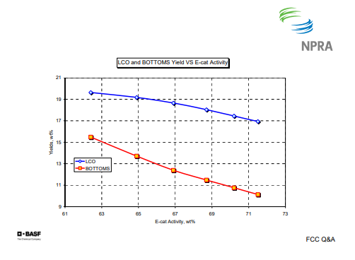
Undercutting gasoline is a flexible option. As I mentioned, it is already commonly practiced, in addition to reduced conversion via lower riser temperature, and/or lower catalyst activity. Unfortunately, the bottom yield tends to increase faster than LCO as conversion is reduced, and I will have some charts in a minute to show that. You can use a heavier feed, but coke, gas, and product quality constraints may limit, for example, the wt% sulfur of some of your products.
With slurry or heavy cycle recycles, second pass yields are very non-selective. High coke and gas yield tend to be the result, with lower quality LCO that will typically require higher air rate or a lower feed rate to heat balance. And when you go to a lower feed rate, it may end up reducing your net LCO production.
Catalytic requirements for maximum distillate: Increased Lewis acidity versus Bronsted acidity decreases the zeolite-to-matrix ratio, which will increase LCO production and give you better bottoms-up grading capability than you get by dropping riser temperature only. In a minute, I will show a slide to demonstrate that. You need a catalyst with good coke selectivity by selecting the right pore architecture. BASF has commercialized products designed for distillate maximization and continues to work in that area.
This is a chart of light cycle and bottoms yield versus e-cat activity. You can see that as you decrease activity—that is, go to the left on the X-axis—slurry yield increases slightly faster than does LCO yield.
The next slide is LCO and bottoms yield versus reactor temperature.
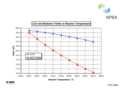
I apologize to my American colleagues for the degree C, but here you see a decrease in riser temperature, once again, going to the left on the X-axis, which gives a much larger increase in slurry than does LCO. So that is generally not the best option.
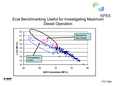
The point of this slide is to show that there is a difference in catalyst. This is data from our e-cat data-benchmarking database. There is a difference in catalyst when you are looking at LCO yield at a given conversion. Your selection of catalyst can impact that, so you definitely want to talk to your catalyst supplier and see what they can do for you in the area of distillate maximization, if that is important to you.
THOMPSON (Chevron)
I agree with the previous comments about undercutting gasoline. That is certainly an option. Cat-to-oil reduction is also another processing option. As far as the catalytic options, bottoms cracking additives are a quick way to get increased LCO. You can also use ZSM-5 to basically make light olefins at the expense of gasoline. The problem there is that you have to make some other moves on the unit. That does not give you more LCO by itself.
The other thing you can work with is zeolite content, as we have mentioned earlier. Zeolite rare earth is another way to handle it, particularly for those who want to make higher quality LCO, since if you reduce rare earth, you are going to minimize hydrogen transfer, which is helpful.
One final comment is that there is not much potential for making distillate when you are processing very paraffinic or highly hydrotreated feeds. Conversion tends to be very high and gasoline is favored over distillates.
WARDINSKY (ConocoPhillips)
As we pushed FCC rates in this industry, one of the things that we have seen is that the diesel range material in your feed typically can be 15% to 20%. And if you think you are going to be in a distillate market for a long time, it is diesel range of material that you are downgrading to LCO, if distillate is valued over gasoline. So you may want to look at upstream projects to get that diesel range material out of your fresh feed. The other thing that we have seen people do is start installing slurry vacuum strippers to try to recover LCO out of the slurry.
One thing I wanted to elaborate on a little bit is severely hydrotreated feedstocks. We have moved a couple of our units to that type of operation and we believe that distillate mode may be limited with that kind of operation, because first of all, there are fewer LCO precursors in the feed following severe hydrotreating. You are also going to want to retain high e-cat activity and high riser severity to keep your regenerator dense bed temperature up.
Finally, in order to maintain level in the bottom main fractionator, we have seen those operations move to try to maximize heat recovery from the HCO and slurry pumparounds. So you are effectively dropping LCO material down into the bottom of the fractionator and losing it there. If you move to that kind of operation, be aware of what the pitfalls may be.
SHANKAR VAIDYAHATHAN (Fluor Corporation)
My question is regarding the heavily hydrotreated feed. Is it 1,000 ppm sulfur severely hydrotreated feed that affects the selectivity to diesel products? Or, at what severity do you begin to affect the selectivity of diesel range material?
WARDINSKY (ConocoPhillips)
We have a couple of units that run with 150 ppm feed sulfur. It is a 2,000 psia hydrotreater. It is putting in about 1,000 SCFB of hydrogen. The light cycle yield is only in the range of, say, 7% to 8%. They are running a 90 to 92 conversion.
THOMPSON (Chevron)
We have a similar operation at one of our units. They make ULSD off of the feed hydrotreater.
KEVIN PROOPS (Solomon Associates)
I would like to thank Mike for his comment. I was going to say largely the same thing; that the FCC is a gasoline-making machine. If this question was motivated by the high diesel prices in 2005 and 2006, the right answer is to get the barrel out of the cat cracker in the first place. Pete Andrews asked me to say that, by the way. [laughter]
If you have a scorecard that says you want to reward your refinery FCC people for keeping the FCC full and keep going on your same project, Mike mentioned to go get some of the gas oils out of the bottoms and put that in the FCC instead. It is the crude vacuum unit sometimes, and it is also coker gas oils in the gas oil hydrotreater. At the refineries where I have worked, we have seen that there is a lot of the diesel in the coker gas oil as well, and that is certainly fertile ground to go chase.
The comment in the question that asks about minimizing impact on LPG yield: In the past, I have seen that distillate tends to make a fair amount of LPG. So if the questioner is asking about maintaining yield, that is easy: That is overcrack. Or just put some ZSM-5 in if you have to, so that should not be an issue. I think the right answer is to keep the distillate out of the FCC when you can.
HEATER (BASF Catalysts)
No.
DOC KIRCHGESSNER (W.R. Grace Refining Technologies)
We have commercialized a catalyst system that we call Genesis and reported on it in our most recent catalogram, which has been issued for this meeting. In it, we discuss the success of this type of technology, particularly for upgrading bottoms into LCO without running into coke selectivity disadvantages. In terms of shifting economics, I think Mike pointed out, or Kevin said, that cat crackers are primarily gasoline machines. But as economic changes require a shift towards higher value for diesel, we find that it is easy to adjust the formulation of these catalysts, both for activity and for upgrade into LCO.
RAY FLETCHER (Albemarle Catalysts)
It might be interesting to let the audience know that Albemarle Catalysts has spent a substantial amount of research on this question of shifting gasoline into diesel. And, as we all know, the FCC is an asset that is designed genuinely for making gasoline. We have a catalyst that is now in the scaling-up process. We gave a presentation in Athens earlier this year, in timing with our patents going public. The catalyst is designed to make the FCC a max diesel engine. This catalyst is capable of increasing the diesel yield by 20% to 25% volume relative. But, at the same time, it reduces the LCO aromatics by 40% to 45% absolute. And if you use just a simple rule of thumb that equates aromaticity to cetane number, which is basically taking the delta in LCO aromatics and multiplying it by 0.6, you get an approximation of what the cetane improvement would be. This would give us an improvement of about 25 cetane number.
This material has been produced on a small scale. We have put it into a small heat-balanced unit running about 200 liters a day, and it produced the same yield selectivities as in our laboratory work. Again, this material is in scale-up. It probably will not be available for sale at least until next year, probably towards the end of next year, but there is light at the end of the tunnel for those refiners who wish to shift their FCC from a gasoline engine to a diesel engine.
ED PALMER (Mustang Engineering)
I had a question for the commercial experience for the severely hydrotreated cat feed, the LCO. By property, as far as gravity, is it still less than 20 and still around 50% to 60% aromatics?
THOMPSON (Chevron)
Yes. I would agree with that because those operations tend to run higher severity. It depends, in part, on your catalyst. If you are running a high activity, high matrix catalyst, you are going to get a lot of hydrogen transfer; and that is going to basically pull hydrogen out of the LCO and into the gasoline. So you can change your catalyst formulation. You can go to a low hydrogen transfer catalyst and help that a bit; but generally, the LCO quality is not nearly what you would expect for good quality diesel.
WARDINSKY (ConocoPhillips)
Gravity is at about the same range as it was prior to the feed shift. I do not know the answer to the aromatics question, whether the aromatics content has changed or not.
JIM WEITH (Mustang Engineering)
You mentioned the vacuum flasher on slurry. I did advise at a refinery in Wyoming where they had this. It was a tower that was hooked onto the side of a vacuum tower. They ran the slurry through it, and reportedly, that was going to pull the distillate out of the slurry and put it into the light cycle or into the light vacuum gas oil that then went off to a hydrofeeder and out somewhere. The vortex meters on it were too big at the time, so we really could not get a real good material balance on it; and I left before those got replaced. It did look like it was doing some benefit. And being close to Halloween, it might be a note that this was called the slurry flasher. But if you listened to people in heated conversations, it got slurred a little bit into becoming the furry slasher.
Submitter
Process
Question 12: For FCC units with closed riser termination device (RTD)/cyclone systems, do you operate with the primary separator sealed or unsealed in the stripper bed? What differences in performance do you see between these modes? Which do you prefer?
WALKER (UOP)
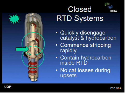
The answer to this question depends on the specific RTD technology. Regardless of the technology, the objective should be the same: a) disengage the catalyst from the hydrocarbon quickly and efficiently—in other words, minimize residence time from the riser exit to the main column entry; b) complete stripping of the catalyst quickly and efficiently; c) prevent hydrocarbon vapors from entering the annular space between the RTD and the reactor where they might overcrack; and d) the design should be robust and able to tolerate upsets and rough startups without catalyst losses.
This is all easier said than done. The question suggests that a catalyst seal is required to prevent hydrocarbon from entering the annular space where it might overcrack. This is one way to accomplish containment. Another way to accomplish containment is to properly design internal hydraulics with sufficient annulus purge steam. In this scenario, the purge steam will flow into the disengager rather than allowing hydrocarbon to escape from the disengager into the reactor annulus. This way, the disengager can operate unsealed. Operating unsealed eliminates the dense bed, submerging the primary disengager, and consequently minimizes hydrocarbon entrainment into the dense bed where it might overcrack.
At UOP, we have designed our VSS reactors both ways. Our VSS riser termination devices are internally stripped, so very little hydrocarbon is entrained into the dense bed. Consequently, at most units, sealing or unsealing is a non-event. However, in a few units, we have observed either a slight penalty or a slight benefit. The disengager hydraulics and stripper efficiency and configuration can impact the results. The secondary cyclones in all of our VSS units are located in the dilute phase and sealed with a flapper valve.
ASDOURIAN (Sunoco Inc.)
We recently installed a couple of two-stage riser termination devices at one of our locations. This device has significantly reduced the dry gas yield, with respect to the previous technology, and it has enabled us to operate higher cracking severity without the associated dry gas penalty. Oddly, we have observed that the dry gas may increase when the cyclone diplegs are sealed. Therefore, it is operated with the diplegs unsealed. The drawbacks to this, of course, are reducing the stripper residence time and the available ΔP across the spent catch live valve.
THOMPSON (Chevron)
We have seven units that operate with a variety of close cyclone riser termination devices, as shown up on the screen. Some operate sealed; some operate unsealed. In addition, we have two units with UOP VSS riser termination devices.
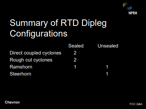
The choice between sealed and unsealed operations is often dictated by the hardware design, since some units can only operate in one mode or the other. For those that can operate either way, the choice is usually dictated by either dry gas make or catalyst losses. We have one unit that starts up unsealed and then switches to the sealed mode when the operation stabilizes.
WARDINSKY (ConocoPhillips)
ConocoPhillips operates several units with close-coupled reactor cyclones of various license or technologies. One of these units routinely operates without the riser or primary cyclone diplegs being submerged or sealed in the reactor stripper bed. Analysis of unit performance does not suggest any degradation in yields, such as an increase in dry gas, by operating with the diplegs unsealed.
DALIP SONI (ABB Lummus Global)
I think whether to seal or unseal the dipleg depends on whether to seal or unseal the primary separator. I think it also depends on the relationship of pressure in the primary separator and the reactor vessel. If the pressure in the primary separator is higher than the rector vessel, it must be sealed to reduce the blowdown. But if the pressure in the primary separator is lower than the rector vessel or the vessel it is containing, then most of the gas will flow up and get recovered. Very little will flow down. In the Lummus Direct Coupled Cyclone System, that is the case. The pressure in the primary separator is lower than the rector vessel so there is no need to submerge the dipleg.
As just an additional suggestion to the industry, I would also like to term this RTD a “reaction termination device” and not “riser termination device” because that is the purpose of this device at the end of the riser.
REZA SADEGHBEIGI (RMS Engineering)
Operators know that when they are sealing the dipleg, they have to use a density tap. They call it an upper density tap. They use this number to find out what its actual catalyst bed level is. Unfortunately, a typical density in that area should be around 35 ppcf to 40 ppcf.
I did a performance audit of a unit a couple of weeks ago. It had just come out of a turnaround where they had put a close-couple cyclone. They found out that the density reading was only 22 ppcf. So if they use that number and they think they are sealed, they will be wrong. One other thing you want to make sure is that you have, indeed, sealed the dipleg, and that the sealing is about three feet above the bottom of the trickle valve or splash plate, depending on which you have. Usually, if you unseal the dipleg, the catalyst separation efficiency improves so you will see a slight drop in ash content versus the seal. The other thing is that you can tell whether it is doing well or not by watching the dilute phase reactor temperature. If that temperature goes up, that means you are dragging hydrocarbon down. Otherwise if it cools off and there is not enough vapor in that area, then you are doing a good job. A properly designed rough-cut cyclone, or primary cyclone, should not let more than 5% vapor go down there. If it does, then obviously there is a fault in the design of that rough-cut cyclone. Either the outlet velocities are too high or the mass flux is too high and is dragging that hydrocarbon down. My recommendation is to please pay attention to that so-called density tap to make sure your actual level is what it out there.
WALKER (UOP)
As far as monitoring the level in the vicinity of the ceiling where that would occur: We install a local level indicator, a very narrow-range level indicator, right in that vicinity so you have high resolution and high accuracy.
WARREN LETZSCH (Shaw Stone & Webster)
I have two comments. One is that you have to understand whether you have either got a positive or a negative pressure cyclone system. Positive pressure cyclone systems require a larger seal than a negative pressure cyclone system. Many people who are running positive pressure cyclones do not have enough of a seal to really get the job done. It usually requires at least three feet of catalyst to be able to do that. If you seal them, theoretically, at the same flux rate going down the dipleg, the amount of catalyst you entrain down the dipleg should be the same, which brings me to the second comment about the flux in the dipleg. As Reza’s mentioned, if the flux is typically high, what they design for, the catalyst is moving down about 3 fps in the dense bed, and that is going to suck gas down with it. If you make the flux of the dipleg much smaller, the catalyst moves at a much smaller velocity. And in fact, the hydrocarbons can turn around and go out the top of the cyclone. So, the design of the cyclone is awfully important, as well as how you operate it.
Submitter
Question 13: With the move toward greater utilization of “opportunity crudes” such as Canadian synthetic crudes, what shifts do you expect in FCC product yield and quality, and how will this impact the operation of the FCC unit?
HOWELL (Holly Refining)
Holly’s choice for opportunity crudes are somewhat limited by our position as an inland refiner and being located far away from many of the crude pipelines. We are making changes in both the way we operate our units, as well as our capital investment, so that we can maintain our current slate with crudes of varying quality. With the opportunity crudes that we do run, we have already experienced increased levels of traditional FCC catalyst poison. Our response to that has been increased catalyst makeup, evaluation of additives, and consideration of custom catalyst blends. We are adding mild hydrocrackers at both refineries and we expect to see a large change in our heat balance. If our crude sources change to include previously upgraded stock or crude blends, then we would expect to see our coke yield and heat balance put back in the direction of where we are today.
As in the rest of the industry, our ultimate goal is to maintain quality products and maximize yields from feedstock survey that will come with discounted and benchmarked crudes. We will continue down this path of making capital investments, catalyst changes, and additive use to try to do that. The bottom line is that we have not yet experienced anything other than that buildup of what we consider to be traditional FCC catalyst poisons. So, expect to see some changes in the very near future.
HEATER (BASF Catalysts)
All syncrudes will be processed by cokers and hydrotreaters ahead of the FCC so there is no single, generic answer. The key will be to crack the fully- and partially-saturated ring structures. With syncrudes, FCC feeds will tend to be less paraffinic and more aromatic with resulting lower conversion. Depending on the degree of hydrotreating, lower gasoline yields will be seen but will have higher octane and benzene content. You will see a higher LCO yield with the lower cetane. You will tend to see higher decant yield with lower API gravity so there is a potential for some fouling issues. BASF is developing catalysts in this area and we will be coming out with something in the very near future. In the Answer Book, I have put a response by our friends in Canada—Incut. There is a lot of detail about different types of syncrudes and the product properties therein.
WARDINSKY (ConocoPhillips)
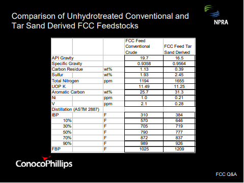
ConocoPhillips is in the process of reconfiguring a couple of our refineries to run large quantities of Canadian tar sand derived feedstocks. This table shows a comparison of feed properties from what the units are currently running and comparing them to some premises that we have for some tar sand derived materials. As you can see, the tar sand derived feedstock is heavier. It contains higher levels of sulfur and nitrogen. It is more aromatic but does not contain as much carbon residue as the conventional crude. The more aromatic nature of the tar sand feedstock is indicated by the comparison of the UOP K factors. The tar sand material does have a higher nitrogen content as well, and the combination with the higher aromaticity should result in a decrease in conversion across the FCC with increased yields of LCO and decant relative to the yields obtained from the conventional feedstock.
KEVIN PROOPS (Solomon Associates)
I believe that this question asks about opportunity crudes. That means people want to make money on this kind of feedstock. I would like to point out that recently, one of the real opportunities is this kind of natural gas. What we saw with our 2006 field study results was that while some of these refiners were experiencing crude advantages versus the Gulf Coast, perhaps, of a few dollars per barrel, natural gas in 2006 was two-thirds the cost of West Texas Intermediate crude on an FLE basis whereas from 1998 to 2004, it averaged about 94% of WTI price. So the money that could be made in 2006 with opportunity high carbon crudes was as much as pumping in hydrogen that came from natural gas as it was in buying those crudes in the first place. I am going to suggest that even though I do not have a crystal ball and I cannot tell you that the natural gas price will remain this time, those refiners that recently could put the hydrogen back into the gas oil probably made the money running these crudes. The FCC obviously is a carbon-hydrogen balance unit. You can reject some carbon with coke; but if you put a hydrogen-deficient feedstock in, you are going to get hydrogen-deficient products back out again. That is hard to get around by most people. I am advocating that if you are going to hydrotreat anyway, when you go to these kinds of feedstocks, the value is probably to get more hydrogen into the gas oil.
RON BUTTERFIELD (Intercat)
We have a northeast refiner who runs predominantly Canadian syncrude and they have been using bottoms cracking additives since mid-2001. It helps to control their bottoms yield. Also, they found that bottoms cracking additive helps to precrack the heavy components at a lower coke yield so they can control a lower temperature in the regenerator.
Submitter
Process
Question 14: What reactions lead to acetone formation and how can they be mitigated? We have measured acetone concentrations between 100 and 1,200 ppm in the FCC butanes/butylenes stream.
WALKER (UOP)
We have very little data on this subject. We did find data on one virgin gas oil operation with 70 ppm to 110 ppm of acetone. If you are getting 1200 ppm, you probably have organic oxygen coming from some type of catalytically converted feedstock or recycle stream. We do not think you can have this level of acetone with pure virgin feedstock.
THOMPSON (Chevron)
We have not detected acetone in FCC butane streams. Oxygenate testing conducted several years ago on an MTBE unit did not show acetone. There is some industry survey information that indicates that acetone levels might be in the 0 ppm to 100 ppm level. However as Pat alluded, it is very likely that the source of acetone is either oxygen or, more likely, contamination from a unit such as a cumene unit that produces acetone as a byproduct.
HEATER (BASF Catalysts)
There is a theoretical chain of reactions to produce acetone in the FCC. Propylene can hydrate to isopropanol (C3H7OH) in the presence of acid sites. However, the equilibrium is heavy in favor of propylene in this reaction. The FCC catalyst provides active acid sites. Isopropanol can decompose to acetone (C3H6O) in the presence of basic sites. Magnesium oxide (MgO) from the SOx additives provides basic sites, as does copper oxide from NOx additives. So theoretically, acetone can be formed from propylene via isopropanol. However, we would expect this reaction to be extremely minor, down in the ppm range.
WARDINSKY (ConocoPhillips)
This response is based on some feedback I got from our HF alkylation experts. They informed me that they thought that acetone formation could be due to the hydrolysis of propylene in the FCC riser, as Rex mentioned. We are not aware of any correlations between acetone levels and the FCC BB stream and the use of something like a ZSM-5 additive to boost C-3 and C-4 olefin yields. Acetone is miscible with water so a properly designed main fractionator overhead waterwash system may be beneficial in extracting acetone to the sour water. FCC BB streams typically contain acetone levels of 50 ppm to 180 ppm. Acetone impurities in BB streams to alkylation units result in increased acid makeup rates and increased acid soluble oil or ASO formation although the increase in ASO formation is not as extensive from acetone being an impurity relative to other impurities, such as dimethylether or methanol. At high levels of acetone in FCC BB stream to an HF alky unit, the ASO properties change and the ASO develops a red discoloration, known as red oil, and that may be more difficult to separate from the acid.
Process
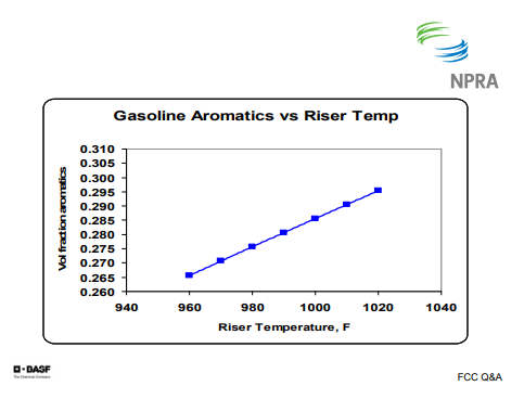
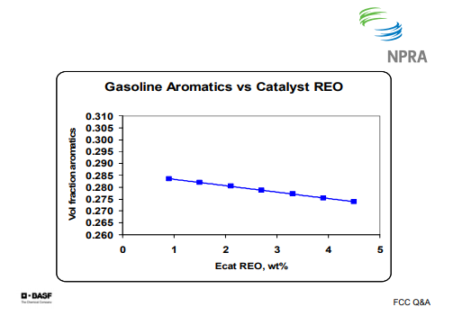
Question 15: What variables influence gasoline aromatics? In particular, please address feed properties, catalyst, and FCC operating conditions.
HEATER (BASF Catalysts)
Feed properties play an important role, namely the amount of one- and two-ring aromatics in the feed. Single-ring aromatics pretty much go straight to gasoline. Many single-ring aromatics in gasoline, however, are formed via reactions; either via cyclization or the cracking of partially saturated multi-ring compounds.
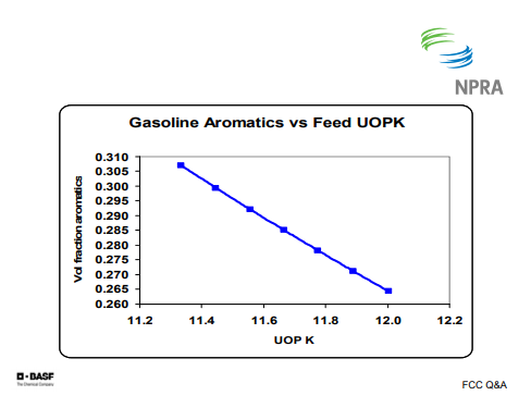
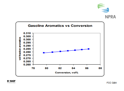
The graphs show where I have plotted gasoline aromatics versus several parameters using data, once again, from our model. The first one shows you that as you go to more paraffinic feeds, you are going to make less aromatics in the gasoline. It is a fairly sharp slope on that.
In the case of gasoline aromatics verses riser temperature, as you raise riser temperature, you tend to increase the gasoline in the aromatics. Once again, there is a fairly steep slope to the curve.
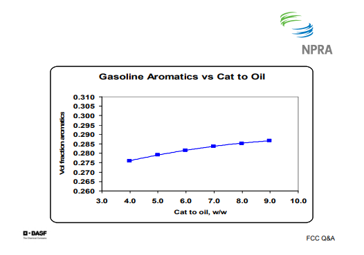
On the Gasoline Aromatics versus Cat to Oil graph, you can see that increasing cat to oil increases gasoline aromatics, but the slope is fairly flat. There is not a gigantic correlation there.
There is a slight increase in gasoline aromatics with catalyst activity, but it is also a fairly flat slope.
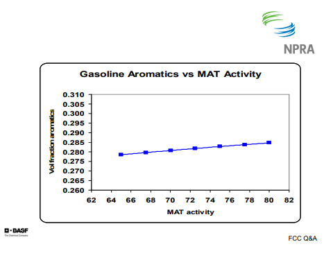
This graph shows, again, a fairly flat slope. When you compare that with the Aromatics versus Riser Temperature graph, you can see that there is a much sharper slope. This one is flatter because of better selectivity and more hydrogen transfer. When it is done thermally, the paraffins, olefins, and naphthenes can overcrack to LPG, which tends to concentrate the aromatics in the gasoline.
This slide shows that as you increase rare earth, you increase hydrogen transfer and you tend to decrease the aromatics. I get asked this question fairly often, but there is not a great deal that can be done, catalytically, to influence the aromatics in the gasoline.
THOMPSON (Chevron)
I agree with the comments that have been made so far. Basically, the feed properties are a big contributor to whether you make aromatic products or not. As far as the hydrogen transfer, ZSM-5, for example, or catalyst properties of ZSM-5 tend to increase the aromatics by a concentration effect. Finally, as far as operating condition, increased riser temperature definitely increases aromatics by dealkylation and cracking paraffins.
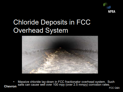
Question 16: A number of refiners are adding a chloride dispersant to address FCC main fractionator overhead system plugging issues. What is your experience with these products and have you had issues with downstream gasoline product quality?
THOMPSON (Chevron)
Processing of increased amounts of imported FCC feed, both gasoline and reduced crude, results in increased chloride salts in the main fractionator, which is usually a result of sea water contamination of transfers. Ammonium chloride salt dispersant is a chemical, which can be used to move or disperse ammonium chloride salts to prevent pluggage of the FCC main fractionator. It is usually injected into the reflux and ultimately is removed through the heavy gasoline and LCO draws.
Usually the dispersant can reduce corrosion by tying up ammonium chloride. Corrosions can still be an issue where the salts accumulate. However, if you have excess water in those locations, the salts can be very corrosive. Also, the dispersant is not very effective in moving salts where there are low velocity or dead zones. Sometimes the salts will accumulate in those areas. One unit experienced massive salt buildup and severe piping corrosion in a low velocity reflux line. The picture shows a reflux line and the salt lay-down. You can get over 100 mpy kind of corrosion under those circumstances.
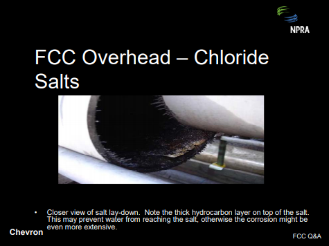
The next picture was taken at a point where we actually opened up the line. It shows the salt deposits at the bottom. The interesting thing here is the hydrocarbons are actually protecting the salt layer so that the corrosion was not as high as you might have expected because the hydrocarbon tend to keep the water out of the salt deposits.
We have not seen product quality issues with using the dispersant, for either gasoline or light cycle oil. However, the units that are using this tend to treat their products downstream because of evidence of chloride salts downstream which result in increased corrosion, but it is unclear whether the dispersant might be an issue. So far, we have not really had a problem with that.
HOWELL (Holly Refining)
Holly is not using this chloride dispersant at either of our facilities. Discussion with our treatment vendor would lead us to believe that in the areas where we are refining, it is not being used by our direct competitors there either.
Process
Question 17: What minimum nozzle velocities are required in air and steam distributors to prevent catalyst backflow and subsequent erosion? Please consider both upward and downward pointing nozzles.
HEATER (BASF Catalysts)
The FCC has many distributors: combustion air, stripping steam, feed nozzles, and torch oil. Many routine FCC problems are the result of poor distributor operation; for example, poor yields due to poor catalyst/oil contact, poor stripping due to lack of catalyst/steam contact, and excessive attrition due to distributor damage.
Common points of nozzle design:
- Standard dual diameter nozzles: You have an orifice controlling the pressure drop to ensure even distribution and no catalyst backflow and a nozzle diameter setting an acceptable outlet velocity.
- You need a sufficient distance from the orifice to the nozzle, such as if there is fully developed flow in the nozzle before it exits.
- You need sufficient cover of the process area to ensure good vapor/catalyst contact. This can be done in two different ways. You can have a large number of nozzles; that is, one square foot per process area. Or, you can have nozzles with high outlet velocity to rely on jet penetration.
Typical distributor and nozzle design includes the following:
- Orifices sized to give pressure drop equal to 30% of static height above the distributor,
- Nozzle outlet velocity of 90 fps to 100 fps,
- Minimum nozzle length of 5.2 times the difference between the nozzle diameter and the orifice diameter (engineering firms tend to use 1.5 to 3), and
- Drains to allow wet media to discharge freely.
To prevent catalyst backflow into nozzles, there are two answers. For a single nozzle, industry standard is to maintain 25 fps velocity in the orifice area. That seems like a low velocity, but that should keep the nozzle clear. For a distributor, the parameter is minimum pressure drop. The guideline is 10% to 30% of static bed height. Commonly, this is 10% for downward facing nozzles and 30% for upward facing nozzles.
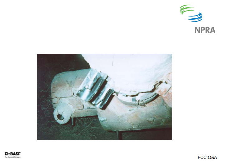
The most likely mechanism for catalyst backflow is the sudden loss of pressure of the flowing media, resulting in instantaneous backflow. This may require waiting until the next downtown to unplug the distributor. Any distributor can experience backflow and plugging if the flow gets sufficiently low.
This is a picture of an air grid where there is severe erosion on the nozzles in front due to the addition of the catalyst.
THOMPSON (Chevron)
We generally focus on nozzle pressure drop rather than velocity as a key criteria for the nozzle design. We limit nozzle velocities to maximum 250 fps and prefer velocities below 200 fps. Recently, design distributors have been designed with air velocities of 80 fps to 100 fps. We follow the industry criteria of 30% of the bed pressure drop for upward pointing nozzles and 10% of the bed pressure drop for downward pointing nozzles.
REZA SADEGHBEIGI (RMS Engineering)
Ralph brought up a good point for designing these nozzles: that it has to have a decent pressure drop. However, one thing you need to keep in mind is that sometimes the engineer who designed this put in his calculation, which comes out to be 1/8 of an inch orifice. You have to use common sense because you can design for four pounds or five pounds or 2 pounds psi. If the hole turned out to be too small, which has happened in many cases, you will plug up that nozzle orifice very quickly. So there should be a minimum requirement on the design of the orifice when you design this distributor because otherwise the catalyst can easily block that orifice and plug the nozzle.
The other thing that you have to think about is: Can the distributor absorb shocks? The support of that distributor is very important because you are never going to have dry catalyst every day, day in and day out. You are going to have water. So if you are going to have a wet catalyst, how is the distributor going to be able to handle that? In the last two years, we have designed four steam distributors that have been installed with great success. These are some of the things that you need to keep in mind, rather than all those velocities and ΔPs.
Mechanical designs: You know, they show you through factory lines so that nozzle velocity is low. Therefore, the attrition rate is—The other thing is that I see in our industry is that lack of communication between a designer and a refiner. Usually, the designer goes to the distributor and they think that, “Oh. Two pound per thousand is good or three pound per thousand.” They put it in and they want to raise the stripping stream because they see that when they increase the stripping stream, the bed temperature goes down. But unfortunately, the stripper was not designed for that. So guess what happens? Attrition goes up. A lot of times, I see that these distributors do not have that flexibility in them. If you design for 5000, can you really go to 10,000 if you needed that?
The other thing is that during startup, especially in a steam distributor, I recommend that you have a provision: If you have a wet steam, put some nitrogen in there. Automatically, nitrogen will come on if you lose the pressure. Or better than that, have a minimum flow around your control valve all the time. Put an orifice in there. That way, if you lost a control valve, you always have minimum amount of stream going through that, which would not plug it. A lot of these problem happen during outages. You lost the power. You come back up—or have attrition. You go to a pressure server; it is partially plugged. They follow all that design criteria. So those are some of the things that you really need to talk to your designer, or whoever it is, to make sure that you have a nice package.
ZIAD JAWAD (Shaw Stone & Webster)
I would agree that different distributor designs may have different criteria. One thing to keep in mind is designs where there is a dampening effect in the bed; for example, in a Model 2 where there is an overflow well and the bottom of the bed does not have fluidized catalyst. You would experience a dampening effect and there may be a difference in the design criteria between different technologies. But in other designs, for example in a reactor where spent catalyst is exiting through the bottom of the bed and the catalyst is fully fluidized above and below the ring, there is less of a difference in the criteria.
Submitter
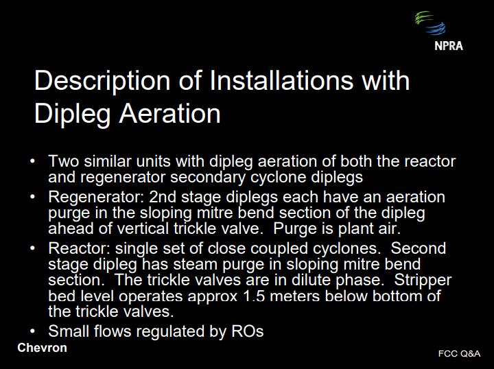
Question 18: Some refiners have installed gas injection in FCC secondary cyclone diplegs to increase capacity and avoid defluidization problems. Please describe your experience operating with gas addition in the diplegs and any maintenance issues. What advice would you give to others considering this installation?
THOMPSON (Chevron)
Cyclone dipleg aeration is a technique used to improve cyclone dipleg fluidization. It involves adding steam, a stream of purge gas—usually air or steam—to the dipleg just ahead of the trickle valve. It ensures that the cyclone dipleg does not defluidize and plug. This can be a problem for lightly-loaded secondary cyclone diplegs.
We have two similar units with dipleg aeration, both are reactor and generator secondary cyclone diplegs. One regenerator has three sets of two-stage cyclones; the other has two sets of two-stage cyclones. Both have air purges just upstream of the trickle valve. Air purge on these purges is controlled by a restriction orifice. These systems have worked pretty well. We have not had any plugging issues with the aeration system or loss of the lines. We also have the system that was installed on the reactor side on the secondaries and that, too, has worked well. Those were actually installed after we had some problems initially after a revamp. There were a lot of concerns about routing the piping: thermal expansion. But on these units at least, it looks like that system has worked out very well and we have not had piping failures.

HEATER (BASF Catalysts)
Some FCCs use conventional pressure taps to measure the flowing catalyst density in the diplegs. Purge gas, typically nitrogen (N2), provides some aeration. External aeration is not a common practice due to poor mechanical reliability of the piping and connections. It is possible to over-aerate the dipleg. The better option is well designed trickle valves so as to not allow defluidization in the diplegs, especially during startups during which the loading can be so light that the residence time is long and defluidization can occur.
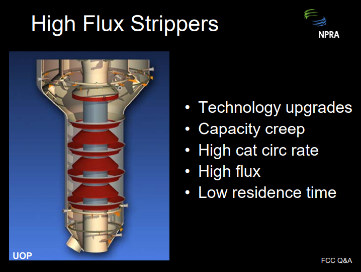
Question 19: FCC revamps commonly include technology upgrades, which increase the catalyst circulation rate, which then increases the stripper flux and reduces the stripper residence time. Please describe your experience with the high flux stripper and its performance. What is the maximum flux you have achieved? What is the minimum residence time you have achieved? Will the use of high efficiency stripper internals reduce the required residence time?
WALKER (UOP)
In addition to technology upgrades, capacity creep is a major factor contributing to ever-higher catalyst circulation rates. Together, these factors are indeed forcing refiners to push the boundary of stripper flux and residence time experience.
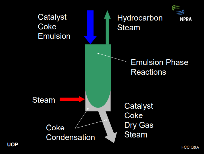
The basic function of the stripper is to recover hydrocarbon product from the emulsion phase, which is entrained with the catalyst after it leaves the riser termination device. This is done using steam that is distributed into the bottom of the stripper. As catalyst leaves the riser termination device, it carries with it hydrocarbon vapors in the emulsion phase. These hydrocarbons should be stripped out as quickly as possible for two reasons. First of all, if the hydrocarbon is not stripped out, it will enter the regenerator and burn there. This will increase the regenerator temperature, reduce the cat-to-oil ratio, drive down conversion, and increase dry gas: all bad things. Secondly, the hydrocarbon vapors in the emulsion phase will continue to react non-selectively in the stripper dense bed, depressing product value.
A catalyst stripper can be readily compared with a reactive distillation column. The emulsion phase and the coke are both reactive. However, the reactions in the stripper are more selective to dry gas and coke compared with the reactions in the riser, so we want to suppress these reactions. The objective is to strip out the emulsion phase as quickly as possible. The coke condensation reactions will continue all the way down the spent standpipe, producing dry gas all along the way, but these are not as harmful as the emulsion phase reactions.
As with ordinary distillation columns, stripping efficiency can be improved by increasing the stripping steam rate, increasing the number of stages, which requires more volume and residence time, or improving the efficiency of each stage. So the answer is yes, use of modern, high efficiency internals will definitely reduce the required residence time.
At UOP, we have several strippers operating at 90 Mlb/hr/ft2 to 120 Mlb/hr/ft2 flux, with corresponding residence times of 35 seconds to 45 seconds. We have two operating right at 120 Mlb/hr/ft2 and one in design for around 130 Mlb/hr/ft2 . Generally, we have observed that strippers with very long residence times do not respond to decreasing stripper level. However, with some stripper internals, we do see a negative response to lower levels for strippers with very short residence times; i.e., under 60 seconds. So this observation does demonstrate that there is a real penalty for ever-shorter residence time strippers and the need for high efficiency internals.
ASDOURIAN (Sunoco Inc.)
I will just speak qualitatively to these questions. High flux stripping has occurred in several of our FCCUs. We found that our annular strippers are most vulnerable. Strippers have been upgraded by adding stages, modifying steam distribution, adding a means for radial catalyst distribution, and/or adding more cross-sectional flow area. Prior to the upgrades, hydrogen and coke ran higher than desired, and obviously these changes improved that situation. Also, regenerator temperature and flue gas percent CO was very sensitive to stripper level and/or stripping steam rates. Upgrades have resulted in the less sensitivity stripper conditions, as well as the lower hydrogen and coke. Also, another side benefit of this is that it results in a reduction in the sour water make if sour water management or conservations are an issue.
SALIP SONI (ABB Lummus)
I think there is some clarification required regarding what the residence time really means because in some strippers—like the conventional design backwards—the residence time is calculated based on the total volume of the stripper, but effective volume is much lower because the stripper area is reduced to the cross-sectional area of the stripper. The catalyst is moving faster than if the whole cross-section area was available to flow. So, I would call that a superficial residence time, but the technical residence time is slower. And if you install the modern devices, they add volume for the catalyst to flow or the cross-section area for the catalyst to flow through, then the catalyst will be flowing slower. Though the residence time appears slower, based on the stripper volume, effective residence time is probably the same. So, Lummus has installed the new advanced modular grade stripper internals in the stripper where residence time is only 30 seconds. It improved the performance of the stripper and reduced the stripping steam rate.
Submitter