Question 12: For FCC units with closed riser termination device (RTD)/cyclone systems, do you operate with the primary separator sealed or unsealed in the stripper bed? What differences in performance do you see between these modes? Which do you prefer?
WALKER (UOP)
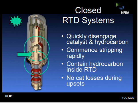
The answer to this question depends on the specific RTD technology. Regardless of the technology, the objective should be the same: a) disengage the catalyst from the hydrocarbon quickly and efficiently—in other words, minimize residence time from the riser exit to the main column entry; b) complete stripping of the catalyst quickly and efficiently; c) prevent hydrocarbon vapors from entering the annular space between the RTD and the reactor where they might overcrack; and d) the design should be robust and able to tolerate upsets and rough startups without catalyst losses.
This is all easier said than done. The question suggests that a catalyst seal is required to prevent hydrocarbon from entering the annular space where it might overcrack. This is one way to accomplish containment. Another way to accomplish containment is to properly design internal hydraulics with sufficient annulus purge steam. In this scenario, the purge steam will flow into the disengager rather than allowing hydrocarbon to escape from the disengager into the reactor annulus. This way, the disengager can operate unsealed. Operating unsealed eliminates the dense bed, submerging the primary disengager, and consequently minimizes hydrocarbon entrainment into the dense bed where it might overcrack.
At UOP, we have designed our VSS reactors both ways. Our VSS riser termination devices are internally stripped, so very little hydrocarbon is entrained into the dense bed. Consequently, at most units, sealing or unsealing is a non-event. However, in a few units, we have observed either a slight penalty or a slight benefit. The disengager hydraulics and stripper efficiency and configuration can impact the results. The secondary cyclones in all of our VSS units are located in the dilute phase and sealed with a flapper valve.
ASDOURIAN (Sunoco Inc.)
We recently installed a couple of two-stage riser termination devices at one of our locations. This device has significantly reduced the dry gas yield, with respect to the previous technology, and it has enabled us to operate higher cracking severity without the associated dry gas penalty. Oddly, we have observed that the dry gas may increase when the cyclone diplegs are sealed. Therefore, it is operated with the diplegs unsealed. The drawbacks to this, of course, are reducing the stripper residence time and the available ΔP across the spent catch live valve.
THOMPSON (Chevron)
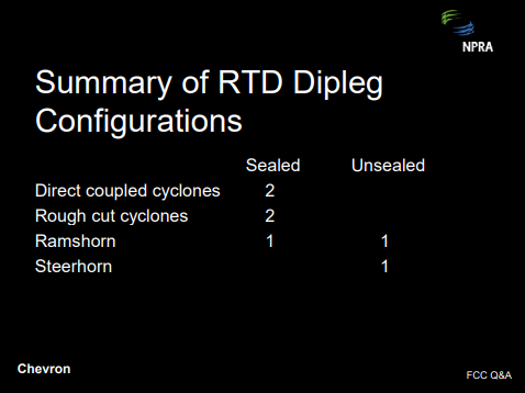
We have seven units that operate with a variety of close cyclone riser termination devices, as shown up on the screen. Some operate sealed; some operate unsealed. In addition, we have two units with UOP VSS riser termination devices.
The choice between sealed and unsealed operations is often dictated by the hardware design, since some units can only operate in one mode or the other. For those that can operate either way, the choice is usually dictated by either dry gas make or catalyst losses. We have one unit that starts up unsealed and then switches to the sealed mode when the operation stabilizes.
WARDINSKY (ConocoPhillips)
ConocoPhillips operates several units with close-coupled reactor cyclones of various license or technologies. One of these units routinely operates without the riser or primary cyclone diplegs being submerged or sealed in the reactor stripper bed. Analysis of unit performance does not suggest any degradation in yields, such as an increase in dry gas, by operating with the diplegs unsealed.
DALIP SONI (ABB Lummus Global)
I think whether to seal or unseal the dipleg depends on whether to seal or unseal the primary separator. I think it also depends on the relationship of pressure in the primary separator and the reactor vessel. If the pressure in the primary separator is higher than the rector vessel, it must be sealed to reduce the blowdown. But if the pressure in the primary separator is lower than the rector vessel or the vessel it is containing, then most of the gas will flow up and get recovered. Very little will flow down. In the Lummus Direct Coupled Cyclone System, that is the case. The pressure in the primary separator is lower than the rector vessel so there is no need to submerge the dipleg.
As just an additional suggestion to the industry, I would also like to term this RTD a “reaction termination device” and not “riser termination device” because that is the purpose of this device at the end of the riser.
REZA SADEGHBEIGI (RMS Engineering)
Operators know that when they are sealing the dipleg, they have to use a density tap. They call it an upper density tap. They use this number to find out what its actual catalyst bed level is. Unfortunately, a typical density in that area should be around 35 ppcf to 40 ppcf.
I did a performance audit of a unit a couple of weeks ago. It had just come out of a turnaround where they had put a close-couple cyclone. They found out that the density reading was only 22 ppcf. So if they use that number and they think they are sealed, they will be wrong. One other thing you want to make sure is that you have, indeed, sealed the dipleg, and that the sealing is about three feet above the bottom of the trickle valve or splash plate, depending on which you have. Usually, if you unseal the dipleg, the catalyst separation efficiency improves so you will see a slight drop in ash content versus the seal. The other thing is that you can tell whether it is doing well or not by watching the dilute phase reactor temperature. If that temperature goes up, that means you are dragging hydrocarbon down. Otherwise if it cools off and there is not enough vapor in that area, then you are doing a good job. A properly designed rough-cut cyclone, or primary cyclone, should not let more than 5% vapor go down there. If it does, then obviously there is a fault in the design of that rough-cut cyclone. Either the outlet velocities are too high or the mass flux is too high and is dragging that hydrocarbon down. My recommendation is to please pay attention to that so-called density tap to make sure your actual level is what it out there.
WALKER (UOP)
As far as monitoring the level in the vicinity of the ceiling where that would occur: We install a local level indicator, a very narrow-range level indicator, right in that vicinity so you have high resolution and high accuracy.
WARREN LETZSCH (Shaw Stone & Webster)
I have two comments. One is that you have to understand whether you have either got a positive or a negative pressure cyclone system. Positive pressure cyclone systems require a larger seal than a negative pressure cyclone system. Many people who are running positive pressure cyclones do not have enough of a seal to really get the job done. It usually requires at least three feet of catalyst to be able to do that. If you seal them, theoretically, at the same flux rate going down the dipleg, the amount of catalyst you entrain down the dipleg should be the same, which brings me to the second comment about the flux in the dipleg. As Reza’s mentioned, if the flux is typically high, what they design for, the catalyst is moving down about 3 fps in the dense bed, and that is going to suck gas down with it. If you make the flux of the dipleg much smaller, the catalyst moves at a much smaller velocity. And in fact, the hydrocarbons can turn around and go out the top of the cyclone. So, the design of the cyclone is awfully important, as well as how you operate it.