Question 75: The butane stream from a catalytic polymerization (cat poly) unit, which contains 69% isobutene, 14% butylenes, and 17% normal butane, would appear to be an excellent alkylation unit feedstock, especially if isobutene is i
METKA (Sunoco, Inc.) We operate a cat poly and sulfuric alkylation unit within the same refinery. The configuration offers flexibility and synergies that allow various operating and business demands to be met. In our configuration, the cat poly debutanizer overhead feeds the alkylation unit to recover the isobutane and any remaining butylenes.
Similar to our other SPA experience, acid carryover from the effluent filtration system typically drops to the bottom of the downstream fractionators resulting in fouling and corrosion of the reboilers. Historically, we have not experienced any significant impact on the alkylation unit or sulfuric acid quality due to carryover from the cat poly unit. If carryover were to occur, we do expect that the phosphoric acid would be more of a corrosion and fouling concern than an acid consumption issue.
Below is a plot that basically shows the way in which the plants are configured. The BB is treated and split to the cat poly and alky units in parallel. Once we recover the C4s off the backend of the cat poly plant, the stream is fed back into the alkylation unit.
Gasoline ProcessesGasolineProcessesFCCDebutDepropBtmsCat GasolineC4,C4=PolyTreaterAlkyContactorsDepropDebutDepropBtmsLPGPolymer GasolinenC4,iC4ContactorEffluentDIBDebutnC4/AlkylatenC4AlkylateMake-up C4iC4PolyAlkyFCCGasolineMixed ButaneiC4nC4Rxr EffluentTreated C4, C4=EffluentTreatingPolyRxrs (FUNKY GRAPHIC)
ZMICH (UOP LLC) I have three points that I would like to make.
1) UOP does not have experience with traces of phosphorus in the alkylation unit feed.
2) UOP strongly recommends avoiding the possibility of phosphorus in the feed. The reason for this is that a combination of mineral acids will lead to a more aggressive corrosion than either of the two acids by themselves.
3) From a commercial perspective, UOP is aware of at least one refinery that feeds cat poly stream with feed from an FCC to an alkylation unit, and the process flow is shown in words as such: “Process flow is a stream goes through a water wash to remove phosphoric acid, the sand tower acting like a coalescer, and a UOP MeroxTM unit to remove sulfur before going to the alkylation unit.
Year
2008
Process
Question 2: We have a Selective Hydrogeneration Units (SHU) unit that removes butadiene from the olefin feed to the alkylation unit. What is the typical concentration of hydrogen and light ends in the olefin product leaving the SHU? How do hydrogen and light ends affect alky operations?
THOMAS PORRITT (Chevron U.S.A)
A selective hydrogenation unit or SHU converts diolefins to olefins in a stream before it feeds an alkylation unit.
Below is a basic flow scheme.

Figure Q2 - 1 Selective Hydrogenation Unit Flow Scheme
The typical composition of non-condensable gases and light hydrocarbons leaving the SHU is dependent upon both the feed and the hydrogen make up. The olefin feed may contain methane, ethane and ethylene in addition to the olefins and diolefins that pass through the reactor. The hydrogen composition can contain a mixture of light hydrocarbons as well as carbon monoxide and carbon dioxide depending on the source. A component balance on these contaminants can show their concentrations in the SHU effluent for the user’s system.
Hydrogen sources vary by nature and quality. Hydrogen produced by a Steam Methane Reformer, SMR, with a pressure swing adsorption, PSA, unit will be the cleanest. PSA units can produce hydrogen that is greater than 99% pure. Not all SMR hydrogen is purified by a PSA. For SMR hydrogen that passes through methanation and chemical absorption, the hydrogen can contain methane and possibly carbon dioxide. At the other end of the spectrum is naphtha reformer hydrogen. This hydrogen can be as low as 70% hydrogen by volume. Reformer hydrogen can contain as much as 8% methane and 6% ethane by volume. The amount of carbon monoxide is dependent on the system pressure of the naphtha reformer. Low-pressure units can produce hydrogen with as much as 30 ppmv carbon monoxide. Excess hydrogen in the SHU leads to oversaturation of the olefins feeding the alkylation unit. In addition, it leads to increased reactor differential temperature and can potentially damage the palladium catalyst in the reactor beds.
The light hydrocarbons and non-condensable gases exiting the SHU pass to the alkylation unit. They then build up and lead to increased pressure in the refrigeration loop. Because they do not condense, they reduce the capacity of the refrigerant compressor and condenser. To manage pressure, the user is forced to vent the non-condensable gases at the refrigerant accumulator. Unfortunately, this venting also leads to loss of iso-butane.
To mitigate these issues the user can proactively clean up the light hydrocarbons in the FCC olefins and better purify the makeup hydrogen. In addition, the user can adjust the hydrogen to olefin ratio by improving control of hydrogen to the SHU. As a final step, the user can vent the gasses at the refrigerant accumulator.
McDermott-Lummus Technology and Dupont Clean Technologies both contributed to this answer.
BILL KOSTKA (Axens North America)
The unreacted hydrogen in the effluent of a Selective Hydrogenation Reactor is very low, typically within the range of 20-50 ppmw.
Methane in the effluent of a Selective Hydrogenation Reactor comes directly from the hydrogen make-up and thus depends on its quality. For PSA hydrogen, the typical amount of residual methane in the reactor effluent is less than 10 ppmw. For a hydrogen-rich stream containing 90 mole% hydrogen and 10 mole% methane, the methane content rises up to typically 500-1,000 ppmw in the reactor effluent.
In a Sulfuric Acid Alkylation unit, ethane and lighter may cause venting from the refrigeration receiver if levels are high. The vent would carry some isobutane, but no sulfuric acid, and would typically go to the flare. A small, packed scrubber may be needed to remove SO2 if venting is done on a continuous basis. Pentanes in the feed cause no operational problems since they will end up in the alkylate product. However, they could result in difficulty meeting RVP and octane targets if these are critical.
RICK DENNE (Norton Engineering Consultants, Inc.)
A typical design would include a downstream stripper or de-ethanizer column to remove excess hydrogen and light ends to the plant fuel gas system. The column would operate in such a manner that propylene/propane loss are minimized, so as to not downgrade their value. Ethane and lighter streams would be rejected. If fractionation is poor, the stream could be routed to the plant’s sat gas unit; however, care must be taken to avoid putting the liquid propane product off test for excessive propylene. If a stripper or de-ethanizer column is absent, the light ends will act as a diluent in the alkylation unit and the non-condensables will cause pressure issues in various parts of the unit. In this case, the owner/operator should weigh the option of minimizing hydrogen to the SHU, at the expense of more rapid catalyst deactivation, versus alkylation unit limits. Improved make-up hydrogen quality should also be considered.
Year
2019
Submitter
Process
Question 10: What causes metal-catalyzed coking (MCC) that obstructs catalyst circulation in CCR reformers? What actions do you take to mitigate MCC formation?
BILL KOSTKA (AXENS NORTH AMERICA)
Metal-catalyzed coke (MCC) formation typically occurs on 3d valence transition metals such as iron and nickel. Under CCR-like conditions of low hydrogen partial pressure (less than about 620 kpa), high temperature (more than about 480 °C) and low or stagnant flow, hydrocarbons can adsorb and completely dissociate on these metals. The resulting adsorbed, dissociated carbon can then dissolve into and change the metal structure. Once a nanosized portion of the metal becomes supersaturated with carbon, carbon begins to precipitate in a tubular crystalline form breaking the carburized-metal fragment away from the parent metal with the carbon nanotube continuing to grow between them. Despite their fragile appearance, these carbon nanotubes are incredibly strong and can readily damage equipment when present in sufficient numbers.
Mitigation of filamentous carbon growth is best achieved by reducing the possibility of hydrocarbon adsorption on the problematic iron surface. Two methods have been used to successfully achieve this goal in CCR reformers: 1) passivation of the metal surface with an adsorbate such as sulfur and 2) use of a more appropriate metallurgy.
Research done by HJ Grabke et al. has shown that very little sulfur, about 0.5 wppm in the naphtha feed, is required to adequately passivate the metallurgy of a CCR reformer. As a result, most CCR reformers are operated with roughly 0.5 wppm sulfur in the feed. Some refiners may rely on incomplete naphtha pretreatment to supply this sulfur, however, addition of a known amount of a sulfur-containing species to the feed ensures adequate passivation on a continuous basis.
Carbon steel is very vulnerable to MCC formation. Alloying carbon steel with increasing amounts of chromium and molybdenum reduces this vulnerability. These two metals tend to migrate to the steel’s surface and greatly dilute iron’s presence there. As a result, there are much fewer Fe-Fe neighbors necessary for hydrocarbon adsorption, dissociation and dissolution into the steel structure. A 9Cr-1Mo alloy steel greatly reduces MCC even at 650 °C. Utilization of this alloy with on-oil sulfur injection virtually eliminates MCC even at 650 °C.
DAVINDER MITTAL (HPCL Mittal Energy)
The catalyst circulation in CCR may be obstructed due to other reasons as well besides metal-catalyzed coking (MCC). However, the metal catalyzed coking presents a serious problem especially in low pressure CCR reforming units.
The processes of metal catalyzed coke formation will cause particles of the heater tube metal to break away from the tube surface. There is also an increased risk immediately following replacement of heater tubes. The coke formed in the furnace tubes may eventually migrate to the reactors and lodge behind the scallops or baskets. These coke deposits can grow until the scallops or baskets are deformed, affecting catalyst circulation, unit performance or even leading to an unplanned shutdown.
The recommended approach is to generally operate the Naphtha Hydro-treating (NHT) unit to remove essentially all of the sulfur in the feed. This will ensure that other contaminants (nitrogen, metals, oxygenates, etc.) are also removed from the feed to the extent achievable by the NHT. Organic sulfur is then added to the CCR reformer unit feed with a chemical injection system pumping in a specific and controlled amount of organic sulfur compound to achieve the target recommended by the licensor. This provides the refiner with independent control of the sulfur in the feed to the unit that can be changed as needed if feed rate or operating conditions change.
Our Continuous Catalytic Regeneration Reformer Unit was commissioned in May’2012. However, within one year of operation, the unit started experiencing several performance issues including restriction of catalyst flow in some of the spider legs of all 04 reactors , higher pressure drop and lower endotherm in reactors (more severe in 2nd Reactor, 60-70% of design value) and lower RON than design.
In view of the above issues, it was decided to shut down CCR during March-April’2014 and inspect reactors. Significant unexpected damage of reactor internals was found.
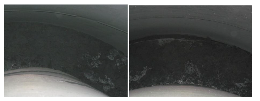
Picture-1: Huge quantity of coke in annular space between reactor grid and shell
Picture-2(a): Last panel of outside reactor grid found fully bulged with huge coke build up
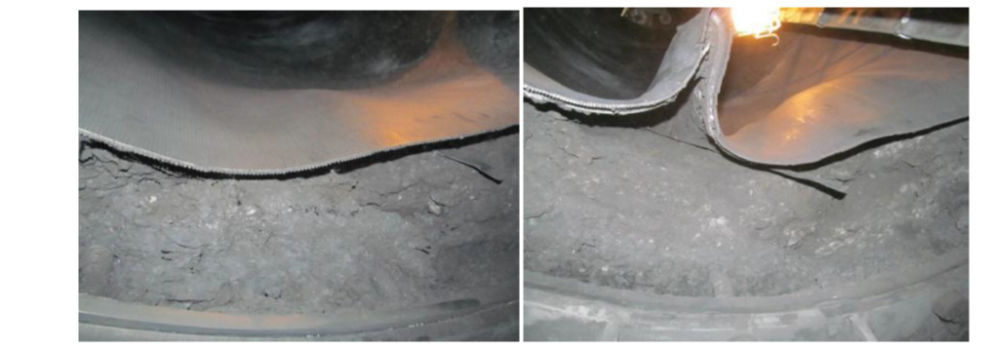
Picture-2(b): Last panel of outside reactor grid found fully bulged with huge coke build up
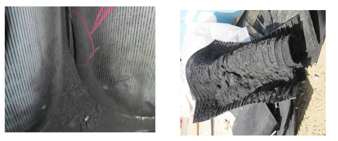
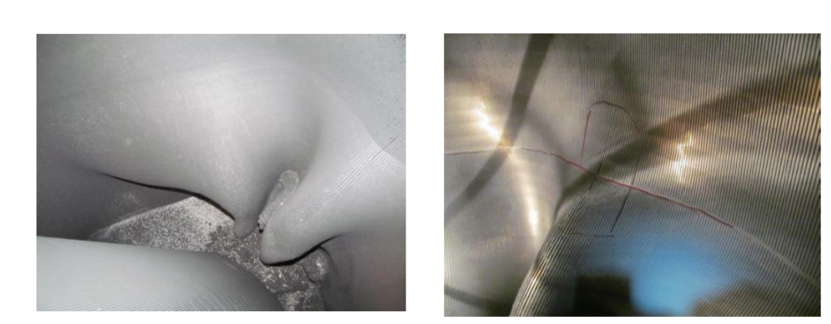
Picture-3(a): Shiny coke between and inside scallops leading to bulging and fish mouth cracks

Picture-3(b): Shiny coke between and inside scallops leading to bulging and fish mouth cracks
A joint root cause analysis with Licensor confirmed presence of Fe and carbon graphite (high carbon content) in the coke samples. During cleaning of the scallops, presence of lot of hard shining coke (metallic coke) was observed along with soft coke. It was concluded that coke build up in reactors/scallops/grids may have taken place due to metal catalyzed coking considering problem with DMDS dosing pump during initial year of commissioning as well as due to other reliability issues like frequent trip of recycle gas compressor. The presence of metallic coke in reactors may have acted as nuclei and further catalyzed the coke growth during recycle gas failure.
The heater tube thickness measurements also indicated some loss of thickness indicating metal catalyzed coking in addition to other forms of coke. The level of thickness loss was fortunately not alarming to inhibit future operation.
Based on root cause analysis certain recommendations were made to minimize metallic coking and damage to reactor internals.
Metallic Coke:
Maintain sulfur level 0.3 to 0.5 ppmw on CCR feed to be substantiated by presence of detectable amount of H2S in recycles gas and 100-150 ppmw of ‘S’ on catalyst sample.
Operate Naphtha Hydro-treating (NHT) unit to remove essentially all of the sulfur and other contaminants in the feed. Inject DMDS in CCR feed through dedicated facility to maintain recommended range of sulfur.
No flame sweeping/scattering on the furnace coils.
Maximum Tube Metal Temperature (TMT) to be restricted below 620oC.
Operation of heater burners within the design regime (maximum allowable process absorbed duty per burner: 1.0 Gcal/h).
Perform positive material identification of tube metal to confirm P9 (confirmed).
Other Coke/ catalyst agglomeration due to coke:
Improvement in reliability of recycle gas compressor.
Check for cold spider legs and try to restore catalyst circulation
Check for quality and temperature of net gas from CCR to avoid condensation in reactor spider legs
Maintain recommended coke ( 4 -5 wt%) on spent catalyst
Stress build up in Reactor internals:
Carry out emergency catalyst circulation in case of unplanned trip of the Recycle Gas compressor to relieve the mechanical stress built up due to difference in the thermal expansion coefficient between catalyst and reactors internals.
Year
2019
Submitter
Process