Alkylation Safety & the Production of Cleaner Gasoline
Issues
Vern Mallett (UOP)
UOP considers that an ESD valve between the cold separator and product stripper is not required and not recommended. The design philosophy behind this practice is to prevent liquid from filling the cold high pressure separator and carrying over into the auto depressuring system and filling the relief header. Once the liquid has filled the depressuring line to the relief header, and if the auto depressuring system were actuated, there is a possibility of damaging the depressuring system and relief lines.
However, some UOP customers require such an ESD valve, which UOP will incorporate into the design of the particular unit. When an ESD valve is specified instrumentation is designed for the ESD valve that will allow the valve close on low level as intended, and then to be reset once the level of the cold high pressure separator reaches approximately 10% of scale above the low level trip set point.
UOP’s philosophy is that the code requires that the downstream flash drum be provided with a properly sized relief valve to handle the loss of level in the upstream drum. Since we have the relief valve at the downstream vessel sized for the loss of level, a cutoff valve in the hydrocarbon line from the high pressure vessel is not going to provide any more protection. In addition, it introduces an additional failure mode that is undesirable. Often such cutoff valve systems are set up with manual reset. Therefore if a low level (or just a system failure) causes the valve to shut, then it is likely that the separator will overflow because the operator may not have time to go out and reset the solenoid valve (or find out what failed and get the valve open again) before the separator overflows. When that happens, the separator and recycle gas line will fill up with liquid and eventually shutdown the recycle gas compressor. At this point the unit is not safe. If it is desired to depressure the unit it will not be possible because the separator and piping to the depressuring system will be full of liquid and therefore the depressurizing capability is lost. The downstream vessel s already protected according to the code. Therefore UOP does not recommend a cutoff valve at the separator
The downstream stripper should have a relief valve that will be sized for the loss of level case per the requirements of the code. The only issue is the location of the relief valve. In order to avoid tray damage on loss of level, the relief valve could be located at the feed tray.
Michael Chuba (Sunoco)
Although this needs to be evaluated on a case by case basis, general practice has been to properly size the relief valve protecting downstream equipment based on the blow through scenario. Doing this eliminates the need for a separate emergency shutdown (ESD) valve between the high pressure separator and the downstream lower pressure rated equipment. If the relief valve is not adequately sized, at a minimum a high pressure protection system or HIPPS system would have to be installed. The HIPPS system is a safety instrumented system (SIS) that would have to be designed with a reliability equal to or greater than that of a pressure relief valve. Thus, the safety integrity level (SIL) of this system could be as high as three or greater. Because the control is on level and the potential fouling nature of the material in these vessels, designing a SIL 3 type interlock is very difficult. Therefore, the preferred approach is to ensure that the CV of the letdown control valve and its bypass valve match the RV of the downstream equipment.
To assist in operation and control of the level in the high pressure separators most recently designed or modified separators are equipped with independent transmitters for High and Low level alarms. In addition LOPA analysis typically finds that an additional independent high level interlock switch is required to trip the recycle compressor if a separate KO drum is not present.
Alan Leute (El Paso Refinery)
For typical Hydrotreaters (up to nominal 1000 psi Separator pressure), we design the Stripper overhead relief valve to handle blow through of hydrogen/vapor from total loss of level in the Separator(s).
There may be additional concerns with this for high pressure Hydrotreaters (greater than 1500 psi Separator pressure) and hydrocrackers, but Western Refining does not have any of these units.
Brian Moyse (Haldor Topsoe)
Topsoe has installed our new promoted zinc oxide product HTZ-51 upstream the reformer section in a number of Ammonia, Hydrogen and Methanol plants. Topsoe’s promoted zinc oxide is also used as a purification absorbent upstream methanator units.
Our promoted zinc oxide product HTZ-51 provides:
•Improved sulphur uptake
•Increased Hydrogenation activity for inorganic sulfur compounds
These benefits will offer the downstream catalyst the best performance and an increase in lifetime as they are protected from both inorganic and organic sulphur.
It can be difficult to get the necessary data from the steam reforming section to verify the benefit of using a promoted ZnO, but we have good data from a purification unit, using HTZ-51 upstream a methanation unit, which clearly shows that HTZ-51 made a big difference. The operating temperature and process conditions are very similar to the conditions upstream a steam reforming application.
The methanation catalyst is also a Ni containing catalyst as is both the pre-reformer and reformer catalyst. The benefits described below will thus be similar to those obtained for pre-reforming and reforming catalysts.
Prior to installing a Topsoe promoted zinc oxide a plant was operating with a non-promoted zinc oxide upstream the methanation catalyst. The plot in Figure 1 clearly indicates that there is a severe deactivation of the methanation catalyst as indicated by the fall in temperature across the bed. Both the non-promoted zinc oxide absorbent and the methanation catalyst were changed out frequently.
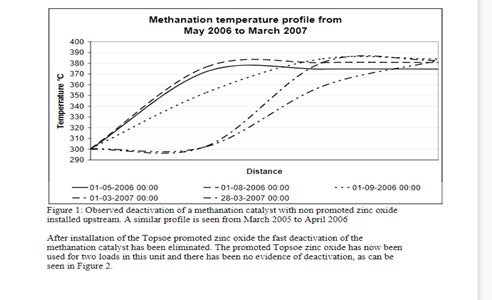
Figure 1: Observed deactivation of a methanation catalyst with non promoted zinc oxide installed upstream. A similar profile is seen from March 2005 to April 2006.
After installation of the Topsoe promoted zinc oxide the fast deactivation of the methanation catalyst has been eliminated. The promoted Topsoe zinc oxide has now been used for two loads in this unit and there has been no evidence of deactivation, as can be seen in Figure 2.
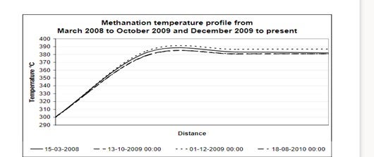
Figure 2: Observed stability of a methanation catalyst with promoted zinc oxide installed upstream.
Thus by installing a Topsoe promoted zinc oxide it is possible to offer the best protection for the downstream nickel catalysts such as prereforming catalysts, steam reforming catalysts and methanation catalysts.
Randy Peterson (STRATCO)
The type of feed is very significant for T90. Amylenes make alkylate with higher T90 in both sulfuric and HF units. Propylene generally makes lower T90 than butylene in HF units. However, with sulfuric-catalyzed technologies, propylene can increase T90 as discussed below. Diene contaminants (butadiene and pentadiene) also raise T90 for both catalysts since they form heavier alkylate. Selective hydrogenation units that remove dienes are therefore helpful in reducing T90.
In sulfuric alkylation, propylene reacted with butylene and especially amylene in the same reactor will lead to higher T90s than if they were alkylated separately. This is due to side reactions that produce heavier alkylate. Therefore, segregated feed systems where different olefins are fed to specific acid stages are beneficial. Normal olefins have lower T-90 and End Points relative to isoolefins. Thus, MTBE/TAME raffinate has lower T-90s than mixed butylene's/mixed amylenes.
For a given feed type in sulfuric alkylation, I/O ratio is the most critical process variable. The lower the I/O, the higher the T90. Low acid strengths also increase T90 so acid staging should be designed to minimize the fraction of alkylate produced at the lowest acid strength.
For HF alkylation, low I/O ratio is also the most significant variable causing increased T90. Acid strengths above 90-92 wt% increase EP and T90 due to the higher activity of the catalyst and tendency for polymerization. Low acid strengths (below 87 wt%) also tend to increase T90 due to increased side reactions and increased acid carryover in the iso recycle. Excessive internal acid regeneration can raise EP/T90 as well.
Higher reactor feed nozzle ΔP and/or increased reaction zone mixing reduce T90 for both catalyst types.
Jamie Chisamore (Johnson Matthey Catalysts)
Feedstock purification is a key unit operation in any Hydrogen plant that employs steam reforming technology. Feedstock purification products are used in hydrogen plants to remove poisons that can affect the performance of downstream catalysts and hardware. The most common catalyst poisons experienced are sulfur compounds present as hydrogen sulfide (H2S), COS, mercaptans, organic sulfides and disulfides, and thiophenes. The key catalysts in hydrogenplants that may be poisoned by trace components in the feed gas are pre-reforming, steam reforming, and low temperature shift. Purification systems are typically designed for a sulfur slip of 0.1 ppmv H2S slip into the steam methane reformer section of a plant at end of run. A traditional purification system containing a sulfur removal system with a hydrodesulphurization bed followed by a zinc oxide based H2S removal absorbent bed, such as KATALCOJMTM 41-6T followed by KATALCOJM 32-5, is sufficient to achieve the necessary design level of sulfur removal levels to protect the downstream catalysts.
Analysis indicates that the total sulfur level exiting the zinc oxide absorbent is typically a few tens of ppb comprising of H2S, COS and traces of organo-sulfur species. The precise levels and mix vary as a function of the feedstock composition, operating conditions and effectiveness of the purification products installed. This low level sulfur slip can still have a negative impact on downstream catalysts for example, if the plant has a pre-reformer or a highly stressed top fired reformer since these are both particularly sensitive to sulfur poisoning. To maximize the catalyst life in these downstream units, Johnson Matthey Catalysts recommends the use of an ultra-purification catalyst, PURASPECJM2084, as a final stage in the purification system. This reacts with and removes the trace sulfur compounds typically to levels below 10 ppbv.
An additional option available from Johnson Matthey Catalysts is KATALCOJM 33-1, which is a unique 3 in 1 purification solution that combines the 3 functions of hydrodesulfurization, H2S removal, and ultra-purification (total sulfur slip less than 10 ppbv) in a single product. This allows simplification in the design, installation and operation of the feed purification system and extends the life of the downstream catalysts.
KATALCOJM and PURASPECJM absorbents use granulation technology to produce spheres with the required combination of properties to maximize the effectiveness of the sulphur absorption in the differing designs for purification beds. These products have been used successfully in many plant operations to improve downstream catalyst performance. For example, a syngas plant suffered from a poorly operating purification system that slipped sulfur to the primary reformer. In order to continue operating, the plant shut down regularly to steam the primary reformer and remove the sulfur. Replacing the purification system with KATALCOJM purification products eradicated the problem saving the plant operator just over two million dollars each year. In another example, when PURASPECJM 2084 was installed on a plant in combination with the traditional sulfur removal system, it resulted in doubling the life of the steam reforming catalyst. This saved the customer over $ 400,000 in replacement catalyst costs.
Praveen Gunaseelan (Vantage Point Energy Consulting)
To focus the question, let us consider a refinery setup where the main hydrogen (H2) sources are the catalytic (naphtha) reformer off gas and an on-purpose steam methane reformer (SMR) for the supplemental H2. It is assumed that pipeline H2 is unavailable. (When pipeline H2 is readily available, it is typically one of the lower cost options to meet incremental H2 demand).
Traditionally, refiners could potentially increase the severity of their catalytic reformers to boost H2 production. However, due to tighter restrictions on aromatics content in gasoline, refiners have had to decrease their catalytic reformer severity, so it is unlikely that the approach will be a viable option going forward.
Existing Steam Methane Reformers (SMR):
There are several approaches to debottleneck existing SMRs to boost H2 production. The optimal approach will extremely plant-specific and depend on the plant's design history, current condition, operating regime, etc. As plant designs are proprietary, it is important to consult with the technology provider or recommended engineering contractors to evaluate your facility and identify the optimal debottlenecking approach. Possible debottlenecking approaches for SMRs include:
•Addition of a pre-reformer
•Replacing the SMR tubes with larger diameter tubes
•Replacing catalyst with higher activity catalyst
•Addition of a secondary reformer downstream
H2 Recovery from Off gas:
There are numerous factors that dictate whether H2 recovery from refinery off gas can be economically competitive, and the decision is ultimately site-specific.
•Market factors can include the price of natural gas (that affects the relative competitiveness of SMR H2), market value of recoverable liquids, etc.
•Technical considerations include the quantity of H2 in the off gas, gas pressure, type of separation technology considered, etc.
•High-pressure gas streams containing H2, such as purge gas from high-pressure hydrotreaters, are generally good candidates for H2 recovery as they require less compression and are richer in H2. For better economics, such off gas sources should not be commingled with lower quality off gas prior to recovery.
•Either membrane systems or adsorption beds are typically used for H2 recovery from H2-rich off gas.
·When high-purity H2 is desired, adsorption is the preferred recovery method.
·Membrane units consume less energy than adsorption beds, and are suitable for lower capacity applications that do not require high H2 purity.
Brian Moyse (Haldor Topsoe)
Typical hydrogen revamp options include addition of a prereformer, (which will allow the use of broader range of feedstocks and a reduction in S/C ratio). With the addition of the prereformer, more of the fired duty in the steam reformer will be used to make H2 and less for steam export. The prereformer can typically increase the H2 production by 10-15%. Another option is to add a Heat Exchange Reformer in parallel with the existing SMR and using some of the WHB heat as heat source for the new Heat Exchange Reformer (may increase capacity by up to 25% and reduce export steam).
Hydrogen recovery from refinery off-gases may be an economical alternative, but one needs to keep in mind that the amount of the PSA purge gas may exceed the need for fuel gas in the refinery. The alternative would be to use the refinery off-gas as feed for the hydrogen plant. The hydrocarbons in the refinery off-gas will then be steam reformed to additional hydrogen. This option may require a prereforming unit or at least a special naphtha type steam reforming catalyst in the steam reforming furnace.
Revamping “Old design” Hydrogen Plants
For revamping hydrogen plants of older design, without a PSA unit, to higher capacity and/or improved energy efficiency, numerous traditional revamp options exist. These options include:
•Upgrading of feed purification and desulfurization section
•Installation of feed saturator •Upgrading of mixed feed preheater to increase reformer inlet temperature
•Reduction of the steam to carbon ratio in the reformer, taking advantage of new high-activity reforming catalysts
•Change of reformer catalyst tubes with thinner wall tubes made from new, stronger alloys
•Introduction of combustion air preheat
•Installation of adiabatic prereformer
•Introduction of new high-activity shift catalysts and re-configuration of shift section
The choice between the options must of course be made on the basis of a careful analysis of the specific situation including the condition of the existing equipment. Typically, a capacity increase of 10-20% can be achieved.
When significant capacity increase (>20%) is desired, this can be achieved by adding a compact convection reformer in parallel with the existing reformer, either a Topsøe HTCR or a HTER convection reformer. HTCR and HTER reformers are very energy efficient and compact reformers that require only a minimum of additional plot area. In order to determine the feasibility of a revamp Topsøe will perform a feasibility study to provide the client with the optimal solution. The study will take into account the status of the existing unit, the various requirements of the client as well as prevailing conditions such as availability and price of feedstock, plot plan, available downtime for revamp etc.
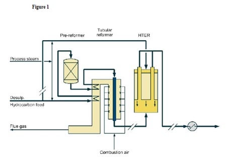
Figure 1 shows a diagram of how an HTER can be incorporated into an existing H2 plant.
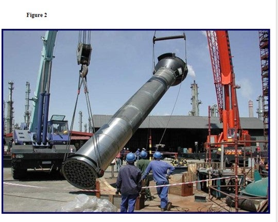
Figure 2 is showing a heat exchange reformer being installed in an existing Syngas plant.
Figure 1
Diane Dierking (Johnson Matthey Catalysts)
There are several revamp options available for debottlenecking an existing hydrogen plant to increase hydrogen production. We will address these individually.
One of the simplest ways to increase production is by enhancing the efficiency of the plant. This might include optimizing performance of all reactors in the flow sheet (steam-to-carbon, operating temperature, etc.) over the life of the catalysts, improving combustion in the steam methane reformer (SMR) such as reduced excess oxygen, balanced firing, etc., and minimizing pressure drop by catalyst selection or optimally shaped supports, such as Johnson Matthey’s STREAMLINE™ products. These types of changes can result in incremental gains in production, on the order of 3 to 5%.
Another method of increasing hydrogen production is to re-tube the SMR with tubes having a larger inner diameter. This will be most beneficial to plants that currently have lower alloy tubes installed. By switching to a higher alloy, such as a micro alloy, the tube wall thickness can be reduced. Maintaining the outer diameter of the tubes while increasing the inner diameter achieves an increase in capacity while minimizing any other changes needed to accommodate the new tubes. Note that the spring hangers or other supports will have to be considered, as will any other hydraulic limitations in the flow sheet. This option can provide a larger incremental gain in production, generally 5 to15% with the larger percentage occurring on older plants that have had little or no upgrades in tube metallurgy over the life of the plant.
Installing an additional reactor into the flow sheet can also increase hydrogen production. The most common reactor additions are to add a low temperature shift bed, a pre-reformer or a post-reformer.
For plant configurations that have only a high temperature shift (HTS) bed, a low temperature shift (LTS) bed can be added to provide greater CO conversion in the plant and will likely also provide additional hydrogen recovery in the PSA. The addition of an LTS bed can allow an increase in total hydrogen production of 3 to 5%.
A pre-reformer can be installed downstream of where steam flow is introduced and upstream of the SMR. The benefits of a pre-reformer are additional feedstock flexibility and greater capacity through the steam methane reformer with minimal to no increase in heat duty. Depending on the feed type, modifications to the existing feed pre-heat coil may be required. To get the maximum benefit from a pre-reformer an effluent pre-heat coil will need to be installed in the convection section to heat SMR feed. The amount of production increase is dependent on operating conditions and the available feedstock but can be from 8 to 15% with the greater increase in production coming from heavier feedstocks.
A post-reformer can be installed parallel to the reformer. Some of the combined feed is diverted to the post-reformer, or gas heated reformer (GHR). The reformer process effluent is used to heat the GHR and drive the reaction, which reduces make-up fuel usage and potentially reduces NOx formation. Depending on plant design, this option can increase plant production 10% to 30%.
With respect to refinery off gases, many of Johnson Matthey’s customers feed refinery off-gas streams to the hydrogen plant. Also, many are beginning to evaluate how refinery off gases might be used instead of natural gas to increase the overall hydrogen availability in the plant. Processing refinery off gas in an SMR is most economical for streams that are not hydrogen rich. On an equal molar feed basis, heavier hydrocarbons will provide more moles of hydrogen product than natural gas; this assumes that the off-gas stream is not hydrogen rich. Also, the heat duty to reform C3+ hydrocarbons is less than natural gas, creating the opportunity to reform more of the refinery off gas. If the refinery off gas is too rich in hydrogen, it is possible that hydraulic limitations might become an issue. For refinery off gases which have more than 35 to 45% hydrogen, the economics for recovering that hydrogen with a membrane or PSA become much more favorable. The residual hydrocarbon/off gas from these systems can then become a more easily reformed feedstock for the SMR.
Michael Chuba (Sunoco)
Sunoco typically looks at the use of isolation equipment on the reactor charge heaters on a case by case basis. The need for these devices is driven by the design configuration of the unit, the process stream being charged to the heater, the emergency depressuring capabilities installed on the unit, and LOPA/HAZOP analysis.
Sunoco’s general heater safety practice is to install a check valve in the combined process outlet of heaters to prevent backflow in the event of tube rupture if there are no downstream vapor depressurizing facilities or liquid blowdown facilities and if the heater operates at 150 psi or higher, and/or if there is a downstream liquid holdup of 350 cu ft or greater. Thus, as previously stated the requirement for a check valve is dependent on the application.
Typically on units where feed to the heater is H2 Treat gas only, these heaters generally have discharge check valves just upstream of where the H2 mixes with the oil as standard practice. On oil only heaters this same practices applies. It is primarily in mixed phase heaters where there is a tendency to find some units with no isolation device and others with discharge check valves. The need for an outlet devise is typically evaluated on a case by case basis. For instance a LOPA analysis on high pressure units with large downstream volume might show the need for additional layers of protection. In this case, a check valve might be added to the design and identified as “safety critical devices”. Being identified as a safety critical device would generally require the valve to be placed on a periodic inspection and test program. Valves of this nature are allowed an IPL credit of “1” during the LOPA analysis. Actuated ESD valves are generally not recommended due to the potential of inadvertent closure and the resulting dead head situation. In most units this would result in the need for additional relief valves for preheat exchanger protection. In addition, if designed with a SIL rating of “1” the ESD receives the same LOPA credit as a discharge check valve.
Vern Mallett (UOP)
UOP’s practice is to install a check valve at the outlet of a recycle gas only heater. UOP does not install a check valve at the outlet of a combined feed heater. The philosophy is that we want to try to keep liquid out of the heater if the recycle compressor stops. Some customers/contractors seem to feel that a check valve at the outlet of the heater will help 3 in some way to prevent a release in the event of a tube rupture at the heater. This ignores the rather large volume of equipment and piping upstream of the heater. In any event the whole unit will eventually depressure through the ruptured heater tube, so the presence of a check valve will not mitigate that. We believe that at least for a combined feed heater, it is better to put the money that would have been spent on a check valve into a more conservative heater design that won’t be as likely to sustain a tube rupture.
If an actuated shutoff valve were placed in this service, it would create a blocked outlet scenario for equipment upstream of the shutoff valve. That scenario might require that upstream equipment be designed for a much higher mechanical design pressure than would be required in the absence of an actuated shutoff valve. UOP does not specify an actuated shutoff valve downstream of a charge heater.
Brian Slemp (CITGO)
The three CITGO refineries have different design heritages therefore different configurations on the furnace outlet backflow prevention. Most of our hydrotreaters do not have backflow prevention on the reactor charge furnace outlets. One of our high pressure hydrotreaters with a recycle gas only furnace has a check valve without an actuated isolation valve. We have never had a tube failure in this system or any other indication that the check valve was ever utilized. The newest hydrotreaters in our system were evaluated for the installation of furnace outlet backflow prevention and the study indicated that check valves were not appropriate. The new unit design incorporated a rapid depressurizing system to minimize the duration and volume of any loss of containment. One of CITGO’s hydrocracking units did have a furnace tube failure and the back flow prevention on the outlet did help mitigate the release inside the firebox.
Praveen Gunaseelan (Vantage Point Energy Consulting)
The question is general; however, there are a variety of steam reformer designs with different operating and control strategies used industrially so a general answer is provided. Operators are urged to consult with their technology providers or qualified engineering contractors for specific guidance on this issue. For simplicity, it is assumed that natural gas is the hydrocarbon feed being reformed with steam. Steam reforming of methane (natural gas) is an endothermic reaction which requires heat input that is typically provided by the combustion of process off-gas and make-up natural gas. A number of scenarios can result in furnace overheating, including:
•Loss of feed flow (resulting in reduced transfer of heat from the furnace)
•Over-firing
•Hot spots in the reformer tubes (e.g. due to catalyst maldistribution, poisoning, deactivation, etc.)
•Flame impingement on reformer tubes, resulting in stress failures
•Inadequate heat removal during start-up
Accordingly, there are a number of strategies to prevent overheating of SMR furnaces that address potential overheating scenarios, and which need to be used in combination to minimize the possibility of an occurrence. Typical strategies are listed below:
•Increased surveillance, both visual and with devices such as pyrometers, during start-up as well as during normal operation
•Minimize the possibility of hotspots (e.g. closer monitoring of catalyst loading, etc.)
•Reduce the occurrence of poor flame patterns
•Implement advanced control schemes to reduce the possibility of or recover from overheating situations
Brian Moyse (Haldor Topsoe)
First of all regular measurements of reformer tube temperatures and inspection of the radiant side of the reformer is very important.
New hydrogen plants will often be designed with software that allows continuous control of the firing duty with proper adjustments made as function of the hydrogen capacity. All the PSA off-gas is used as primary fuel and the firing control is handled by the secondary fuel.
Obviously a proper catalyst loading with only a minor variation of tube pressure drops is mandatory for proper flow distribution through the tubes. Maldistribution may cause individual tubes to overheat.
Proper catalyst selection and operating conditions should be adopted to avoid carbon formation on the process side, which will lead to hot-banding and tube overheating.
Burner operation should be checked regularly to avoid flame impingement on the tubes.
The Haldor Topsoe reformer furnace is designed to allow for profiling of heat input from burner rows, resulting in catalyst tubes operating at a higher average temperature and heat flux at lower peak tube temperature. This profiling of heat input in itself reduces the risk of overheating of the furnace, but also the measurements of the tube skin temperature made on a regular basis will prevent from operating the reformer with too high tube skin temperatures.
However, the biggest threat to the tubes is a sudden over-heating, which will damage the tubes very rapidly. This could in principal be due to:
•Loss of cooling (feed)
•Too high fuel input (overfiring). Fuel is controlled with a duty controller, summarizing all fuel duty input.
To prevent from such sudden over-heating, the reformer is protected by low feed and steam flow trips, and the fuel is controlled with a duty controller, summarizing all fuel duty input, to prevent overfiring.
Further, as secondary protection, the reformer is protected by flue gas temperature measurement. This is the fastest indicator of over-firing, as process gas in a cold collector can increase in 15-30 seconds if the firing is increased rapidly and a high temperature trip is initiated.
Brian Slemp (CITGO)
The best strategies to prevent overheating steam methane reformer tube:
1)Ensure the catalyst tubes are pressure drop balanced. Reformer furnaces have an inlet manifold to evenly distribute the feed. An increase in pressure drop from an improperly loaded catalyst tube will reduce the flow of the reactants in that tube increasing the tube temperature and potentially leading to coking and overheating.
2)Routinely monitor the skin temperatures and balance the fire box heat distribution to prevent localized hot spots.
3)Prevent direct flame impingement.
4)Routinely monitor catalyst activity with your vendor to prevent operating in the carbon deposition region and generating internal thermal insulation thereby overheating a tube.
5)Maintain proper steam to carbon ratio.
6)Monitor feed composition to ensure potential coke precursors are not introduced above allowable limits.
7)Ensure high purity steam is used to prevent catalyst poisoning and coke generation.
8)Closely monitor tube temperatures and nitrogen flow during startup.
Tina Moss (Johnson Matthey Catalysts)
If not monitored properly, a variety of operating issues can lead to high steam reformer furnace tube wall temperatures. High tube wall temperatures are most often due to poor catalyst loading, problems during start-up operations, or carbon formation due to poisoning. Therefore, the best strategies to prevent overheating of steam reforming furnaces are to address the operating issues that can cause high tube wall temperatures.
The first step in avoiding high tube wall temperatures is to ensure a good catalyst loading that avoids flow imbalances and large catalyst voids. The general tolerance on flow variations between tubes is ± 2.5% for a good catalyst loading, which corresponds to a pressure drop variation of ± 5%. The most common loading technique used by North American refiners is the trickle loading method. There are several trickle loading techniques available in the market and these can typically achieve between 2 to 5% pressure drop variation.
Problems that result in furnace overheating often occur during plant start-ups. Feed flow imbalances on the process side of the reformer tubes often occur during start-ups when rates are significantly less than design. To minimize the impact of the feed flow imbalances, nitrogen flow needs to be sufficient to provide a heat sink as the burners are going through a sequenced start-up. Once steam flow is introduced it provides a significant heat sink but needs to be at least 30% of, and preferably 40 to 50% of the design rate as soon as possible to allow even firing of the furnace. In addition, the operating pressure during start-up should be kept low to maximize process gas velocity and hence improve gas flow distribution as well as minimize the pressure differential across the tube walls reducing the stresses on the steam reformer tubes. While these concerns are most prevalent during start-ups, these conditions can also be present when there are significant rate fluctuations.
Another source of high tube wall temperatures is the result of catalyst deactivation. High tube wall temperatures can occur due to carbon formation caused by insufficient steam rates or poisoning of the catalyst. Insufficient steam to carbon ratios can result if steam flows are not appropriately modified following feedstock changes. Low steam flow can result in carbon deposition on the catalyst and overheating of furnace tubes. Poisoning of the catalyst that results in carbon formation is typically due to sulfur. The best strategy to prevent catalyst deactivation by poisoning is to ensure good purification operation and monitoring during operation. In the event that carbon formation has occurred, one potential strategy is to steam the catalyst to remove the carbon formed. This is most effective if the catalyst loaded in the top is alkali promoted
. Steam reforming furnaces are very expensive, complex units. Overheating of these units can result in reduction in hydrogen production and equipment failure. Creating a strategy to address proper catalyst loading and start-up procedures, as well as, transient conditions during daily operation will help to avoid steam furnace overheating.
Emerson Domingo (Sunoco)
The critical flow nozzle (CFN) is located on the underflow line of the Third Stage Separator (TSS). The purpose of the critical flow nozzle is to continuously help blow down cat fines separated in the TSS. The nozzle is normally designed for 2-4% flue gas and designed to take the same pressure drop as the Expander.
The performance of the TSS can be adversely affected if the underflow line is plugged by a cracked or collapsed CFN. In that case, the catalyst backs up in the TSS and goes to the expander instead. The other mode of failure can be the erosion of the CFN holding flanges and cone, which could potentially result in leaking flue gas and catalyst to atmosphere. In either case, a shutdown may be needed if expander blade deposits and expander vibration become unmanageable or the CFN boxes kept on eroding.
Paul Hewitt (Tracerco)
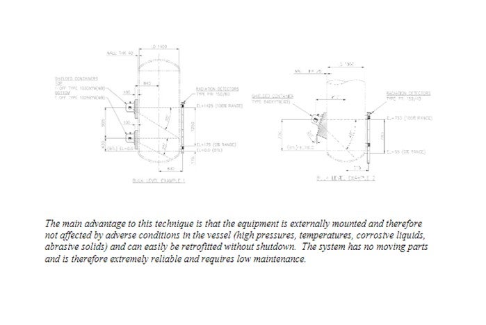
Due to the relatively “dirty” nature of crude tower and main fractionator bottoms fluids nuclear gauge technologies are commonly used for continuous bottoms liquid level measurement. The main benefit of nuclear gauge technology is its non-contact design.
A radioactive source is housed in a lead filled container, which emits a collimated beam of radiation. When the vessel is empty this penetrates the vessel wall, across the inside of the vessel, through the other wall and is incident upon the detector. An angle is cut into the container that allows a specific vertical range to be covered. Figures 1 and 2 show general arrangement diagrams for the external source variation used for bulk level control, alarm and critical process shutdown. As the level of liquid in the vessel rises to the detector vertical position, it attenuates the radiation reaching the detector. This causes a decreasing pulse rate to be produced by the radiation detector, which is then converted into a 4-20 mA or digital signal. Typical nuclear gauge instruments typically incorporate many advanced features to enable accurate and reliable level detection, including:
•Automatic correction for radioactive source decay,
•Automatic correction for changes in vessel operating pressure,
•Linear and logarithmic linearization options for level correction,
•Extensive self-checking and error reporting facilities,
•Digital Interfaces
Jeff Lewis (BASF)
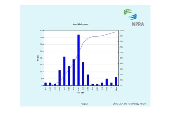
The histogram below shows the distribution of iron content for all ecat samples BASF receives. It should be noted that fresh catalyst has an iron content of about 0.55 wt%. The histogram shows that the median ecat iron concentration is approximately 0.62 wt%. This suggests the median contaminant iron level on ecat is 0.07 wt%.
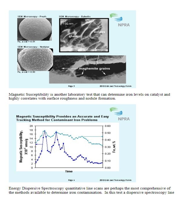
There are several methods available to quantify iron contamination on catalyst. Scanning Electron Microscopy (SEM) pictures are a valuable means to qualitatively assess iron laydown morphology on the catalyst particle. The three images below show varying degrees of iron contamination on a catalyst particle. The first picture shows a fresh catalyst particle that is free of contaminant iron on its surface. The second picture shows a catalyst particle with a significant concentration of iron nodulation on the catalyst surface. The third picture shows a low boiling eutectic formed in the presence of an alkali metal like Ca or Na and is the severest form of iron poisoning.
David Hunt (Grace Davison)
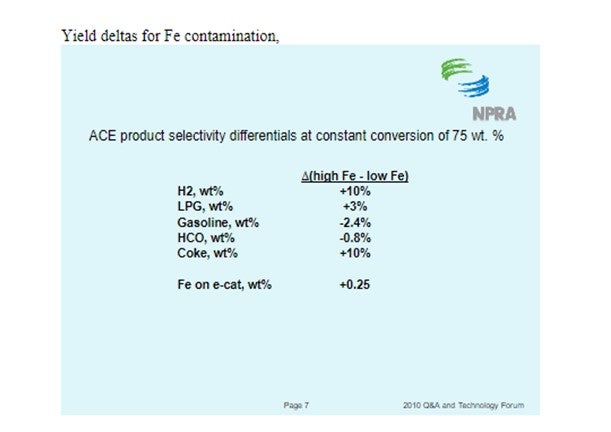
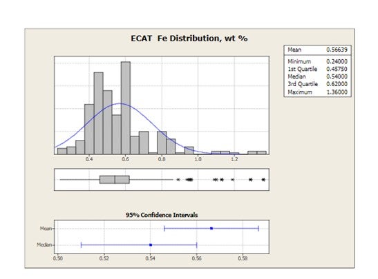
Grace receives E-cat samples for most of the FCC units operating worldwide. The figure below shows the distribution of average equilibrium catalyst Fe levels for 2010 for all FCC units that have provided E-cat samples to Grace. Mean Fe levels are 0.57 wt% and the highest Fe level in one unit is 1.36 wt%.
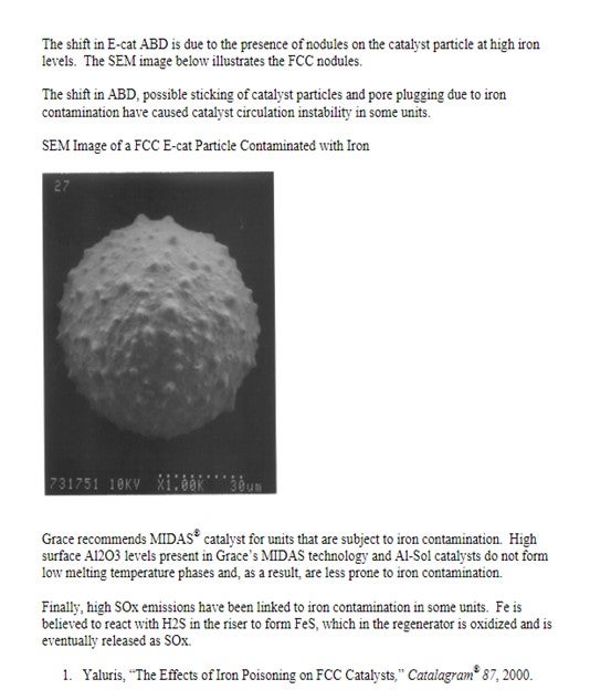
Iron can be detrimental to the unit in many ways including bottoms conversion, catalyst circulation stability and SOx emissions.
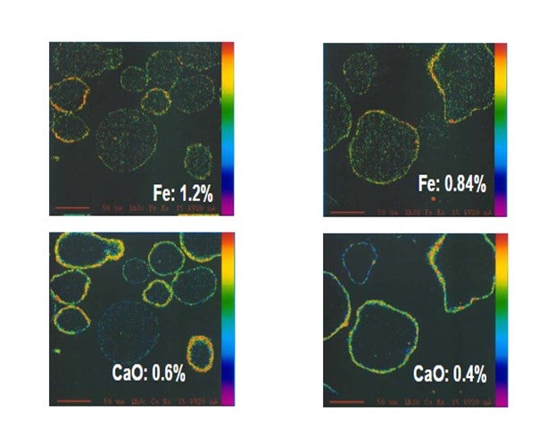
Yaluris (1) showed using an Electron Probe Micro-Analysis (EMPA) technique that iron from organic iron sources is primarily a catalyst surface contaminant. Yaluris also used scanning electron microscopy and optical microscopy techniques to confirm Fe is a surface contaminant. The figure below is an EMPA image of an FCC catalyst particle cross section. Warmer colors on the surface of the particle confirm that Fe and CaO are primarily surface contaminants. EMPA Image of Two FCC Catalyst Particles
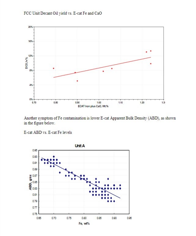
Yaluris (1) discussed how Fe contamination can lead to pore closure and nodule formation. The presence of Na and CaO can act as fluxing agents, aggravating the effect of Fe. The figure below shows Decant Oil or Main Fractionator bottoms yield vs. E-cat Fe plus CaO levels. Decant Oil increases at the higher contaminant levels due to the damaged catalyst pore structure.
Brian Moyse (Haldor Topsoe)
The operating conditions for ULSD vary and will depend on the feed to be processed as well as specific requirements to the product quality. This is apart from the typical US and European standards for ULSD, such as low aromatics, color, cold flow properties or other additional specifications.
Topsoe has been involved in the design and/or revamp of more than 80 ULSD units, plus our catalysts are the most widely used in ULSD service worldwide. In the study phase for a grassroots unit one of the first decisions we make is the choice of operating pressure. Once the pressure is fixed, all other operating parameters (LHSV, H2/oil, reactor temperatures) including catalyst are chosen. All of the process parameters inter- correlate and the final solution should also be able to function with up-stream and down- stream equipment. If an existing unit is revamped into ULSD the refiner may want to use as much of the existing hardware as possible to reduce CAPEX. In this case the unit pressure is fixed.
In case of a simple catalyst replacement in an existing unit, the catalyst system is optimized to provide the client with highest NPV over the lifetime of the catalyst. The prime objective is to meet the product specifications for fixed cycle length, and once this is met, we look into factors that will reduce cost. Low H2 consumption, low operating temperature, high diesel yield, use of second generation ULSD catalysts, regenerated catalysts, etc are some of the secondary objectives that will reduce the cost. In a time when the refinery margins are low, many ULSD hydrotreaters are using from 30 to 100% regenerated or reactivated (ReFRESH TM) catalysts at the cost of cycle length or feed capacity. With the current lower demand on the ULSD supply this is an acceptable solution.
Below we will present some very general operating conditions and catalyst solutions for three ranges of the operating pressure:
· Low H2 pressure: < 600 psi
· Medium H2 pressure. 600 to 950 psi
· High H2 pressure: > 950 psi
Low H2 pressure: < 600 psi
At low pressure it will often not be possible to remove the basic nitrogen compounds that inhibit desulphurization via the hydrogenation route, and as a consequence a CoMo catalyst is preferred. It is possible to co-process some cracked feed, but since the reactions are slow the LHSV will have to be reduced. The hydrogen consumption will be modest compared to operation at higher pressure due to less aromatic saturation, and the
unit can therefore operate with a low H2/oil ratio. Topsoe’s industry leading CoMo BRIM™ catalysts are installed in units that operate at an H2/oil ratio as low as 250 SCF/bbl at a reactor outlet hydrogen pressure of less than 150 psi. With such low hydrogen availability and pressure, a CoMo catalyst with a high activity for the direct desulphurization route is required, and use of NiMo will only lead to both poor start-of- run activity and high deactivation rate. The temperature during the cycle is ranging from 610 to 740°F, but we have experience with units that start at 715°F and reach end of the cycle at 770°F. The LHSV can be anywhere between 0.5 to 5 hr-1.
Medium H2 pressure: 650 – 950 psi
Operating at medium pressure is not well defined. If the inhibiting N species in the feed are removed the fast hydrogenation route can be used with NiMo preferred and if they cannot, the slower direct route will predominate and CoMo is selected. Since cracked feedstock’s have a high N content, the ratio of these in the feed blend will in essence be dictating the choice of NiMo or CoMo. If the hydrogenation route can be used but the H2 availability is too low to cover the consumption, it is possible to load some CoMo together with the NiMo, but this will reduce cycle length.
This is illustrated in Figure, 1 based upon testing of 100% CoMo, 100% NiMo and three stacked bed configurations of CoMo/NiMo at 640 psi H2 on a feed containing 70 wtppm
N. In this test all N is removed and the 100% NiMo loading, which has the highest hydrogenation activity, also shows the highest HDS activity and the highest H2 consumption. The lowest activity is obtained with 100% CoMo, but this system also consumes less H2 than any other loading. The three stacked bed solutions are in between these two extremes, both in terms of HDS activity and H2 consumption. It is therefore possible to balance activity and H2 consumption as needed for a specific unit.
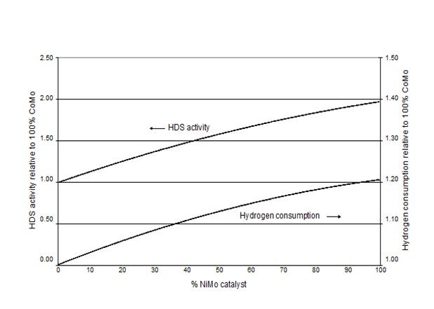
Figure 1: Pilot plant testing of 100% CoMo, 100% NiMo and three combinations of CoMo/NiMo at 640 psi H2.
From the above it is obvious that the required H2/oil ratio is highest when using NiMo and lowest with CoMo.
The EOR temperature is generally lower when a NiMo catalyst is used compared to a CoMo solution. This is because the N cannot be removed due to equilibrium constraints at high temperatures, and with higher contents of organic N in the oil the hydrogenation route cannot be used. Since the NiMo has a low activity for the direct desulphurization route it is not recommended to operate at these conditions. In some Asian countries there are specifications on product color, which also deteriorates with temperature. Some of the units Topsoe have designed for this part of the world are equipped with our color removal technology (polyshift) downstream the HDS section in order to operate the HDS catalyst at a higher EOR temperature.
High H2 pressure: > 950 psi
In high pressure operation a NiMo is in general the preferred choice due to its high hydrogenation activity. Despite the favorable pressure the LHSV is still in the same range, but as the aromatic saturation increases with pressure these units need to have a high H2/oil ratio, sometimes higher than 6,000 SCF/bbl. High pressure units are used when very difficult feedstocks are treated, e.g.,
crudes of South American origin or any feedstock containing more than 50% cracked LCO.
Michael Chuba (Sunoco)
Sunoco has multiple hydrotreating units including one hydrocracker that produce ULSD. These units' range in operating pressures from 475 to 1450 psig with EOR temperatures ranging from 670-770F, depending on pressure, feed, heater RACT limitations, and/or metallurgical temperature limitations.
The majority of our ULSD units use high efficiency CoMo catalyst. Now that we are into our second and third loads, we have begun using a combination of regenerated and fresh catalyst loads. Initially we had limited the use of regenerated catalyst to the top beds or in applications where the service was not as severe. With experience, we have found good activity with the regenerated material and have pushed more and more regenerated material into the mix with as much as 100% regenerated catalyst in some of reloads.
As for how many times ULSD catalyst can be regenerated, this depends on the condition of the catalyst. The main limitation to multiple catalyst regenerations is catalyst L/D. In applications employing vacuum catalyst unloading the abrasive handling of the catalyst can result in particle L/D of less than 2. Below this range we would typically not reuse this material. Other criteria for not reusing catalyst are high metals and other contaminate levels. Overall, multiple regeneration of ULSD catalyst can be done.
Charles Olsen (ART)
The types of catalysts being used in ULSD are typically current generation, high activity Type II catalysts, and the catalyst loadings cover the range from 100% CoMo catalysts for lower pressure units to 100% NiMo catalysts for higher pressure units with no H2 constraints. A large percentage of units have been using a combination of NiMo and CoMo catalysts as in the SmART Catalyst System® from Advanced Refining Technologies. The SmART system is based on a staged catalyst approach utilizing a high activity CoMo catalyst like 420DX for efficient removal of sulfur via the direct abstraction route and a high activity NiMo catalyst like NDXi which effectively removes the multisubstituted dibenzothiophenes via the hydrogenation route.
One of the big advantages of using a staged catalyst approach like this is illustrated in the figure below. The figure shows that as NiMo catalyst is added to the catalyst system there is a large increase in HDS activity relative to all CoMo reference, and eventually, a maximum in HDS activity is reached.
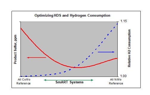
The position and magnitude of this optimum varies with feed and operating conditions, especially H2 partial pressure. The figure also includes the relative H2 consumption, and again, as the percentage of the NiMo component increases, the H2 consumption relative to the base CoMo system increases. Notice, however, that in this case the relationship between H2 consumption and the fraction of NiMo catalyst is nonlinear. In the region where the system shows the highest activity the hydrogen consumption is only slightly greater than that for the all CoMo system, and well below that for the all NiMo catalyst. It is this ability to balance HDS activity and H2 consumption to meet individual refiner requirements that sets SmART apart.
Exact start of run conditions will of course vary with feed and operating conditions, but a typical SOR WABT is around 640-660°F. The typical ULSD unit has a LHSV around 1 hr-1 with an inlet pressure of around 850 Psig, although ULSD unit pressures vary from a low of around 500 Psig to a high around 2000 Psig. Observed deactivation rates have been in the range of 1-3°F/mo depending upon the feed and operating conditions.
End of run conditions have been determined by a unit constraint such as a reactor inlet temperature limitation or some product attribute, most commonly product color. We’ve observed, as an average, an EOR WABT around 730-740°F. It’s important to note that for diesel product color it is the reactor outlet that is important. We’ve observed reactor outlets as high as 760°F in some cases with no detrimental impact on product color.
There are also a number of ULSD units which suffer from Silicon and Arsenic poisoning. These units tend to have shorter run lengths and will include a sizeable bed of guard catalyst to protect the active catalyst below.
Perhaps somewhat surprising is the number of ULSD units which have exceeded expectations in terms of cycle length. Many grassroots and revamped units were designed for 2 year cycles and actually ran 3-4 years. For the units which have changed out we’ve seen catalyst loadings which include adjustments to the relative amounts ofNiMo and CoMo catalysts, the addition of new, higher activity catalysts which weren’t available when the unit started up, and in some cases a portion of catalyst load is made up of reactivated catalysts. These reactivated catalysts are regenerated and further processed to redisperse the active metals using proprietary processes such as PHOENIX™ which was developed by ART and is now currently offered by TRICAT. In most of the latter cases reactivated catalyst makes up only part of the reactor fill with the remaining volume new catalyst.
Dave DiCamillo (Criterion Catalysts & Technologies)
Actually, some ULSD units containing Criterion catalysts are still on their first cycle, some due to use of 2nd generation ULSD catalysts in units designed on 1st generation products or operating with a significantly easier feed than assumed in the design basis. Each ULSD operation is unique, so there is not a single answer to the first part of this question (See also response for Question 22).
· SOR operating conditions are dependent on the unit design and feed quality. We have observed SOR temperatures ranging from 600 to 700°F. Obviously the more robust the unit design, the lower SOR temperature is likely to be.
· EOR operating conditions are dependent on refinery objectives for things like fixed or flexible turnaround/catalyst changeout date. With a flexible EOR date, the refiner can run the normal ULSD feed until the run becomes limited by reaching charge heater or catalyst activity limits. In many units, aromatic saturation thermodynamic equilibrium still limits the ability to make sulfur or color specs at EOR, however the maximum temperatures achievable are higher than originally anticipated, particularly in units processing only straight run feeds. Maximum reactor outlet temperatures remain a strong function of feedstock type, operating pressure (H2 partial pressure), catalyst type and LHSV.
There is also no single answer to the second part of this question - catalyst selection. Catalyst selection can depend on many factors such as:
· Unit design
· Feed quality
· Product quality requirements
· Hydrogen consumption and availability
· Cycle length targets
· Cost
· Refinery philosophy on catalyst type, e.g., fresh only, internal reuse, resale catalyst, etc.
Discussion of next cycle expectations with your catalyst supplier will help to formulate objectives, especially if they differ from the current operation. The best approach is to be clear on processing objectives (minimum requirements and desired targets) and prioritize them in the catalyst RFQ (request for quotation) so that vendors can provide some options to consider. A catalyst supplier will typically have a portfolio of products that can be customized for different operating modes such as maximum cycle length, maximum feed rate, minimum hydrogen consumption, etc.