
Question 9: What has been your experience with antimony and phosphorous poisoning on hydrotreating catalyst performance? What is the maximum level?
Kaspar Vogt (Albemarle) Antimony (Sb)
The effects of antimony in oil on hydrotreating catalyst have not been directly studied, but we can infer the likely impacts of antimony from a variety of information sources and past experiences.
As background, contaminant metals such as nickel can deposit on the FCC catalyst. This will result in increased dry gas (H2 in particular) and delta coke. Depending on the unit constraints this can lead to lower FCC conversion and lower feed rate. Many refiners use antimony in the FCC riser to passivate the detrimental effects of nickel. Antimony will cover the nickel enriched catalyst surface. Side effects are that the Sb will also cover the CO and NOx promoter metals and make these additives less effective.
Excess antimony mainly accumulates in the FCC slurry. However, antimony can be present in the heavier FCC products which are hydrotreated downstream. If the antimony enriched FCC catalyst fines are entrained into the hydrotreater, they can deposit in the catalyst interstices. This will impact bed pressure drop but not catalyst activity. The bed pressure drop build up can be managed by a guard bed catalyst system of sized and shaped catalysts to increase the void fraction and create more particulates capacity.
By analogy with the FCC experience, we would expect antimony in oil to preferentially coat nickel and cobalt promoter metals on the NiMo and CoMo catalysts. Ultimately, this would completely poison the catalyst. During the buildup of coating/poisoning, the activity will likely see a shift towards direct desulfurization (DDS) vs. indirect/aromatic saturation, thus the hydrogenation-to-hydrogenolysis ratio will change. A given concentration of Sb on catalyst would be expected to have a more severe effect on the catalyst performance in high severity HDS/HDN operations like ULSD and hydrocracker pretreat (HC-PT) service than in lower severity hydroprocessing applications such as NHT and LSD.
We seldom, if ever, detect antimony in the interior of spent hydrotreating catalysts where it would be expected to impact activity.
Furthermore, given its position in the periodic table, we would expect that Sb attacks the catalyst's active (NiMo and CoMo) sites, and that it would be a relatively severe poison, similar to arsenic (As), sodium (Na) and lead (Pb). Therefore, we would expect ≤1.0 wt% Sb would reduce HDN/HDS relative volumetric activity (RVA) by approximately 50% in non-severe applications, and that even lower Sb concentrations could severely reduce catalyst activity for high severity operations like ULSD and HC-PT.
Phosphorous (P)
Phosphorous (P) can come into the hydrotreater feed from:
- crudes
- drilling fluids
- phosphated ZSM
- phosphorous-based corrosion inhibitors and flow improvers
- phosphorous from solid phosphoric acid catalyst
-biofeeds
In catalyst manufacturing, phosphorous added on hydrotreating catalyst acts as a promoter and provides additional acidity to enhance HDN, hydrogenation and cracking reactions. Phosphorous also improves metals dispersion on the catalyst surface.
In one instance, we saw that 3 wt% of phosphorus on the catalyst terminated all the exotherm in bed, although other poisons where also present. Organic phosphorous can penetrate into catalyst pores. In general, our understanding is that the poisoning was similar to sodium where ~1.0 wt% concentration halves the catalyst activity.
In a separate instance, we found SiP coming from a solid phosphoric acid catalyst, used in certain FCC gasoline desulfurization processes with some iron deposited at the external surface of the catalyst extrudate. Some phosphorous and silicon also penetrated the catalyst pores. However after the first 0.1 mm, no contaminant phosphorous and silicon were found on a main bed CoMo catalyst. In this case, a layer of P-Si-Fe had deposited at the pore mouth and restricted the diffusion into the catalyst.
Photos of the outer surface including chemical composition are shown below. They show that Alumina, Molybdenum and Cobalt are homogeneously distributed within the catalyst particle, while phosphorous, silica and iron are located at the outer surface of the particle.
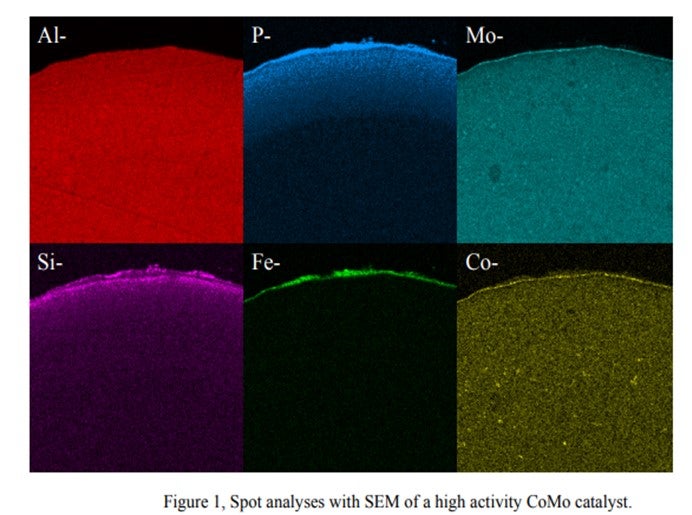
We observed that the Si & P from this process behaves totally differently from Si from anti-foaming agents. There are Si-P particles which cannot penetrate the internal pores of the catalyst and are deposited on the catalyst outer surface. The accumulation of these particles cannot be prevented. Therefore, sooner or later, bridges from particle to particle are formed, thus causing pressure drop buildup.
The bottom line is that the quantitative effects of phosphorous on hydroprocessing catalyst performance and the maximum allowable levels are highly dependent on the source and form of the phosphorous compound. It is also dependent on catalyst properties and the process application.
Martin Gonzalez (BP)
Phosphorus can sometimes be found in crude as alkyl phosphates added to passivate metals or protect against naphthenic acid corrosion. Phosphorus esters in crude may originate from waste oils, or from additives injected into wells to improve recovery. Some of the phosphorus may be in a form that volatilizes into distillate fractions bound for hydrotreaters. We have encountered some Canadian crudes containing phosphorus originating from fracturing fluids used in production. Phosphorus content in light sweet crudes seems to be declining, but it may be becoming more prominent in heavy crudes. There have been reports in the industry of ULSD units suffering catalyst deactivation as result of phosphorus from these crudes. From our experience, at 1 wt% on catalyst, it is reasonable to expect a 15-30% activity loss.
Charles Olsen (ART)
Phosphorous (P) contamination in oil has been traced to frac fluids that are often used in crudes from the Western Canadian Sedimentary Basin. The source is diphosphate esters which are soluble in the crude oil. Refineries that run large percentages of light Western Canadian crude have reported crude column and crude furnace fouling for many years. Improvements made to crude columns to minimize fouling have transitioned the depositing of phosphorous to the downstream hydrotreaters.
Other sources of phosphorous include gasoline slop tanks, imported feeds and lube oil wastes. If phosphorous does manage to make its way into the hydrotreater it will poison the active sites of the catalyst causing a loss in activity. A level of 1 wt% of phosphorous on the catalyst results in roughly 10°F loss in activity. ART recommends that a feed content of < 0.5 wppm be maintained whenever possible as well as the use of feed filters to assist in trapping of phosphorous sediment.
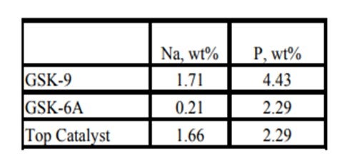
Historically, phosphorous contamination has not been very common, but with the increasing use of opportunity crudes it is being observed more frequently. A recent example is summarized in the table below shows the results of some spent catalyst analysis from a diesel unit. This unit experienced extremely rapid catalyst deactivation shortly after start up. It was so severe that within several months the unit required an unplanned turnaround and fresh catalyst was installed. The spent catalyst analysis indicates the catalysts were exposed to high levels of several poisons including sodium and phosphorous. The contaminants penetrated well into the catalyst bed. The level of contaminants indicates the catalyst in the top half of the bed had lost over 60°F of activity.
Year
2011
Process
Question 26: When you test for free HF and organic fluorides in alkylation unit products (alkylate, butane, propane), what are your typical observed levels? After HF breakthrough in our butane product, why does our treater still have plenty of KOH remaining? Is there any way to regenerate KOH during the run? Do others maintain a heel of KOH in the bottom of the alkylate storage tank to neutralize traces of HF?
Erik Myers (Valero)
These series of questions overlap quite a bit. The following answers address each question in the approximate order of those questions.
Our sites vary in the type of testing with most sites testing for combined (organic) fluorides in at least the propane and butane streams. Multiple stream points are typically tested dependent on what the monitoring goals are. Typical levels upstream of any treating are:
• Propane - 200 ppm
• Butane – 600 - 1000 ppm
• Alkylate – less than 100 ppm
Combined fluorides measured upstream of treating can be used as an indication of the completeness of the alkylation reaction. There will always be some level with the typical values noted above. Higher levels indicate potential issues with the upstream operation. The above values are for typical operations. Key contributors to increases in combined fluorides are low acid strength (below 85%), low reactor temperature (less than 80 o F), decreased contact time and low I:O ratio. Any of these can lead to increases in the amounts of all levels of combined fluorides. Propyl and butyl fluoride can increase by orders of magnitude with low acid strength. Post treatment levels of combined fluorides should be well under 10 ppm, typically.
Defluorinators are typically installed on the propane and butane streams, followed by KOH treating. These systems are occasionally used on the alkylate product stream. Water and HF are the products of the defluorination reaction. HF reacts with the defluorinator alumina to make aluminum fluoride trapped as part of the defluorinator alumina. This leads to potential of trace HF in the defluorinated stream if the remaining active alumina does not convert the HF. There is typically a lead – lag arrangement on the defluorinators to allow continued treating of the product streams. The downstream KOH treater is installed to dry the defluorinated product and remove any trace HF. It is less common to have a lead – lag for the KOH treaters but two of our sites have this arrangement on at least one stream. Some of our sites have water collection pots upstream of the KOH treaters to lessen the load of those treaters. To measure the effectiveness of the defluorinators and as an aide in determining optimum change out frequency, the streams are ideally measured before, between and after the treaters (with the downstream measured after KOH treating). The sample between the lead and lag defluorinators is used for confirmation of whether an alumina changeout is required. The upstream sample, along with the product flow rates can be used a predictive tool in scheduling lead defluorinator changeouts. The spent alumina can also be sampled and analyzed by the alumina supplier and compared to these predictive results for further alumina changeout optimization as well as verification of the hydrocarbon stream fluoride testing. One site uses a typical fluoride concentration and then a throughput totalizer to determine changeout timing, then analyzing the spent alumina to confirm loading.
Aside from the trace HF noted from the defluorination reaction free HF should not exist in the alky propane if the HF Stripper has adequate reflux and never show up in the normal butane or alkylate product. The primary cause for free HF is spent alumina in the defluorinators or severe loss of tower temperature profile in the alkylation fractionation tower(s). less than 1 ppm. Only one of our sites typically checks for free HF with the values being less than 5 ppm.
The KOH treater is typically a walnut bed downstream of the defluorinators. Our sites utilize both walnut and flake KOH, with walnut being typical. Our units are split with 50% have upflow and the other half downflow. This is typically an indication of the original unit licensor design. As noted earlier, water and HF are the products of the defluorinator. If the there is an HF breakthrough to the KOH treaters, it is most likely due to a spent defluorinator, where there is no more alumina to react with the HF. Significant breakthrough is important to avoid. Large amounts of free HF can cause the KOH treater to heat up resulting in hydrocarbon vaporization and unfavorable conditions for HF removal. (In a propane KOH treater, melting of the KOH and then freezing it in the outlet piping has actually been observed). One of our sites has an emergency alarm for high butane KOH treater outlet and delta temperature with another site having an SIS diversion for high C3 KOH treater temperature. The noted upstream and downstream sampling of each defluorinator is a key to staying on top of this processing area of the alky.
If KOH is still present in the treater while HF is measured in the product it is most likely caused by poor distribution through the KOH bed, either from channeling or crusting on the top of the KOH bed, sometimes caused by low amounts of water in the feed to the KOH treater. This low water content prevents the removal of KF (formed by the reaction of the KOH and the HF) from the KOH treater. Our sites have utilized either routine steam or water injection to the KOH treaters to prevent this.
Circulating KOH (typically used in the acid relief system neutralization system) can, and typically is, regenerated in a batch mode. We are not aware of a method to regenerate the solid fixed bed units as the KOH is converted to water and drained from the system. Three of our sites have two KOH treaters (either in parallel or series), allowing monitoring and changeout to be accomplished without compromising product quality. Residual KOH / water from the KOH treater changeouts can be utilized for make up in the circulating KOH system noted above.
Only two of our sites presently utilize a caustic heal in the alkylate product tank. This has been utilized at other sites in the past. This was done either as a preventative measure or as a result of previous issues with tank bottom corrosion. It is a common recommendation from the licensor. If this method is used, the tank water draw should be monitored frequently to measure changes and prevent loss of protection. The mechanism for tank bottom corrosion is either HF breakthrough from slumping of the fractionators, an exchanger leaks that routes acid to the tank or water in the alkylate product tank that leads to hydrolysis of the combined fluorides in the alkylate to HF if the residence time in the tank is long enough. The noted monitoring of any water draws and then ensuring that there is not water is another preventative measure for this.
Brad Palmer (ConocoPhillips)
Typical organic fluoride levels in alkylation unit products, upstream of any post-treatment, have been reported as 40-60 ppm (Alkylate), 200-400 ppm (Butane), and 300-600 ppm (Propane). Inorganic fluorides are not typically measured. Defluorination and KOH treating will reduce propane and butane organic fluorides to 10 ppm or less. Inorganic fluorides will be less than 1 ppm after treatment. Thermal defluorination, occurring in the heater passes, can further reduce organic fluorides in alkylate. Maintaining the fractionator bottom temperature above 320°F will thermally defluorinate any organic fluorides in the tower bottom thereby minimizing organic fluorides in the alkylate.
Un-used KOH material at breakthrough signifies bed channeling and/or a very dry system that allows KF to coat the KOH material. Defluorinator chemistry reacts organic fluorides with alumina to form alumina fluoride and water; an intermediate reaction product is HF, which may leave the defluorinator unreacted. The KOH treater is primarily a dehydrator and secondarily an HF neutralizer. As the KOH dries the LPG stream, the water "cleans" the KOH as it makes a sludge that is drained from the vessel. Any HF breakthrough from the defluorinator will react with the KOH to form KF and H2O. If there is very little organic fluoride to react in the defluorinator, there will not be much water formed to slough the KF off the KOH pellets. Some sites have used water injection to help "clean" and utilize the KOH material under dry conditions.
There is no effective way to regenerate solid KOH in the KOH treater with the vessel on-line. Water injection might be effective to refresh KOH that has been coated with KF as previously described.
It is a common practice to use an alkali heel in the alkylate storage tank. This is not for neutralizing HF, but is to counter-act iron fluoride scale leaving the process with alkylate which can form low pH hydrates on the tank bottom. The alkali heel should be tested routinely to ensure it remains basic.
Year
2011
Process
Question 16: What is the typical carbon monoxide (CO) concentration in the reformer net gas? How is the CO content measured? What are the potential effects to downstream units from the CO?
MELDRUM (Phillips 66)
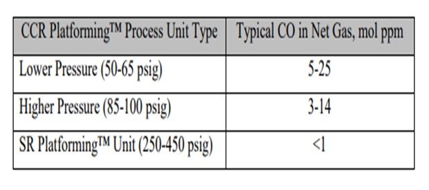
Carbon monoxide can form in reformer units as the hydrocarbon reacts with moisture under very low-unit pressure conditions. Typically, semi-regeneration reformer net gas would have nil CO and only a minimal amount in a CCR-type unit. I expect it to probably be on the order of 5 ppm (parts per million), though some units report routine measurements of 10 to 20 ppm CO in their net hydrogen off gas.
One of our cyclic units that was operating at 400-pound had CO as high as 20 ppm in its net hydrogen stream when the recycled moisture rose to around 300 ppm. The excessive water entered the reformer from a leaking side reboiler on a wet debutanizer that used a slipstream of the reformer reactor effluent as the heat source. The water then returned to the reformer product separator. The high CO caused deactivation in the catalyst in a downstream isomerization unit.
Accurate measurements of CO in the net gas are difficult. Reformer units are not expected to have much CO, so they seldom have an online analyzer. A colorimetric tube – Gastec or Dräger type – can be used to give an indication of the presence of CO, but accuracy for a quantified number is difficult and requires the use of a carbon pre-tube to remove the hydrocarbons.
CO is detrimental to downstream hydrogen-using units in three principal areas. CO in hydrogen being fed to a distillate hydrotreater will methanate, consuming the hydrogen that would have otherwise been used for the desulfurization reactions. This will have the effect of lower catalyst activity. CO in hydrogen fed as a makeup stream to an isomerization unit will also methanate and form moisture that will deactivate the isomerization catalyst. CO that did not methanate in the second example could act as a poison to the platinum metal function of the isomerization catalyst. UOP suggests a CO limit of 1 ppm max for isomerization hydrogen makeup gas. My Answer Book response also includes some of the common steps used to minimize CO formation in reformer units, particularly in a CCR unit.
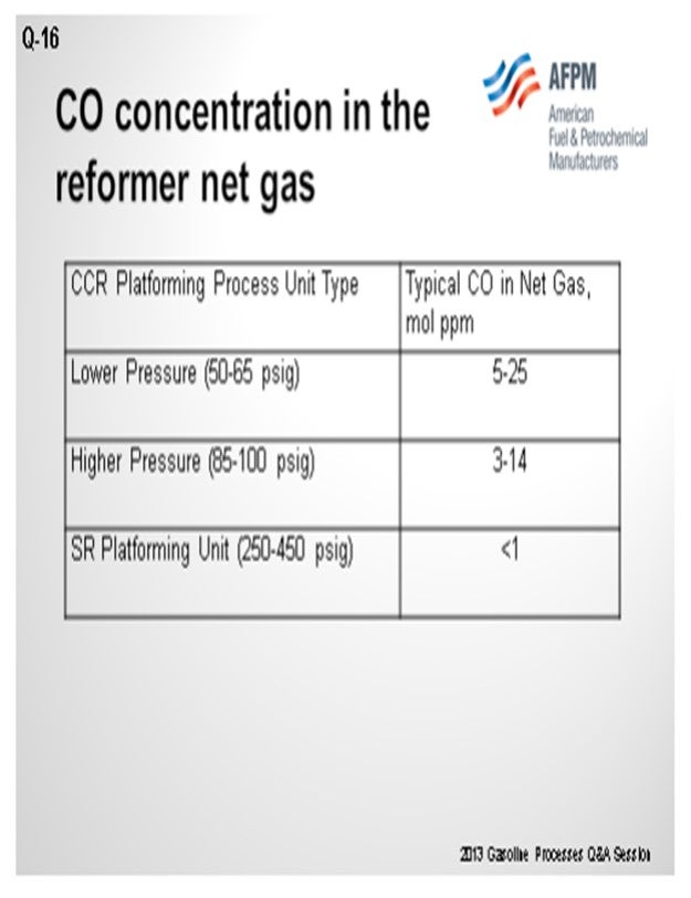
BULLEN (UOP LLC, A Honeywell Company)
As you can see in this table, we have correlated some different types of operation and ranges of CO levels. As Craig alluded, the numbers vary quite a bit, which can be due to conditions in the unit, as well as analytical capabilities. There seems to be a trend that the lower pressure units generate more CO than higher pressure units.
The laboratory method we recommend using is UOP 603, which is a laboratory method for CO and CO2 and hydrogen. However, a lot of refiners cannot do this method. The gas detection tube route is fairly common. Our point of view is that with the gas detection tubes, if one carbon pre-tube is good, then two is better. So, we usually ask them to use two tubes instead of one to help eliminate the breakthrough of hydrocarbons that can make a false high value for CO.
As Craig said, the issue with chloride and alumina isomerization catalyst is that you will deactivate the catalyst. However, if you are using another type of catalyst, like the Par-Isom catalyst or zeolitic catalyst, the actual suppression you will get will be very dependent on what temperatures you are running. As you approach the 400°F temperature, you tend to methanize the CO in the first part of the bed. So CO tends to have less of an effect on the metal function of the isomerization catalyst and becomes more of an issue of activity suppression due to the water on the acid sites. The same would apply if you had a saturation unit with platinum catalyst. It would also behave in a similar manner to these higher temperature isomerization units.
R.K. (RICK) GRUBB (Chevron Products Company)
Another aspect needs to be mentioned for the lower pressure reforming units. You have to take into consideration your nickel carbonyl formation when you shut down a hydroprocessing unit that is using the reformer hydrogen. You may have to either swap the hydrogen source or think of another shutdown procedure that will ensure no nickel carbonyl formation.
CRAIG MELDRUM (Phillips 66)
CO is detrimental to downstream hydrogen using units for three principal reasons:
1) CO will methanate in HDS (hydrodesulfurization) units consuming hydrogen, which will take away catalyst activity.
2) Much of the CO will methanate in isomerization units, forming water that will deactivate the isomerization unit catalyst.
3) The non-methanated CO in the isomerization unit will poison the metal function of platinum on the catalyst.
Note: The UOP suggested CO limit on isomerization unit hydrogen makeup gas is 1 ppm (10 ppm for CO + CO2). UOP reports that CO levels greater than 6 ppm will not allow the isomerization unit catalyst to meet its cycle life guarantee.
The common steps to minimize CO formation in the reformer are:
• Minimize moisture in the system (feed water control and good regeneration drying),
• Minimize the last reactor temperature,
• Maximize the H2/HC ratio, and
• Minimize catalyst circulation rate in a CCR.
PATRICK BULLEN (UOP LLC, A Honeywell Company)
The CO concentration in reforming unit net gas can be impacted by a number of factors: system pressure, temperature, and moisture in the recycle gas, as well as the H2/HC (hydrogen/hydrocarbon) of the operation. Operating pressure has the most significant impact on CO production in a reforming unit. CO formation in reforming operation is produced via steam reforming of hydrocarbons:
H2O + CH4 ↔ CO +3H2
Thermodynamically, this CO formation reaction is more favorable at lower pressures. CO production is inversely proportional to the pressure squared. As such, a semi-regeneration reforming unit, being significantly higher pressure than typical continuous reforming units, will tend to produce less CO than a typical continuous reforming operation. Likewise, the lower pressure high severity reforming unit operation is more favorable for CO productions.
Commercial reforming net gas CO data from CCR Platforming™ process units can range from 1 to 40 mol ppm. The table below indicates typical ranges for various unit types. Typically, CO levels in the semi-regeneration reforming units are at trace ppm levels due to the high pressure and low-moisture range operation.
For testing of CO in reformer net gas, UOP recommends method UOP 603 for trace CO and CO2 in hydrogen. For CO in light gaseous hydrocarbons, analysis by GC is recommended. Analysis by gas detector tubes can also be considered for measuring CO at elevated levels when used with several carbon adsorbing pre-tubes.
CO in reforming net gas can have an impact on downstream users that may be sensitive to CO or H2O that may be formed due to the reverse steam reforming reaction, also known as the methanation reaction. In the case of a Butamer™ and Penex™ catalyst, water is a permanent deactivator. A typical rule of thumb is that 1 pound of H2O kills 62 pounds of Butamer™ and Penex™ catalyst.
For other types of catalysts, such as Par-isom™ Process and zeolitic isomerization catalysts that operate at higher temperature, the water generated from methanation of CO is a temporary activity suppressant. Platinum-based BenSat™ catalyst behaves similarly to these isomerization catalysts.
GARY HAWKINS (Emerson Process Management)
With respect to the second part of the question, the carbon monoxide content, as well as other components in the net gas of a naphtha reforming unit, can be measured with a variety of measurement principles depending upon the accuracy and reliability required, other species present that may interfere with a particular technology, and the expected range of concentration of carbon monoxide. These same comments apply to measuring other refinery gases, such as the net hydrogen and PSA (pressure swing adsorption) tail gas from steam reforming units for hydrogen production.
Year
2013
Process
Question 10: What causes metal-catalyzed coking (MCC) that obstructs catalyst circulation in CCR reformers? What actions do you take to mitigate MCC formation?
BILL KOSTKA (AXENS NORTH AMERICA)
Metal-catalyzed coke (MCC) formation typically occurs on 3d valence transition metals such as iron and nickel. Under CCR-like conditions of low hydrogen partial pressure (less than about 620 kpa), high temperature (more than about 480 °C) and low or stagnant flow, hydrocarbons can adsorb and completely dissociate on these metals. The resulting adsorbed, dissociated carbon can then dissolve into and change the metal structure. Once a nanosized portion of the metal becomes supersaturated with carbon, carbon begins to precipitate in a tubular crystalline form breaking the carburized-metal fragment away from the parent metal with the carbon nanotube continuing to grow between them. Despite their fragile appearance, these carbon nanotubes are incredibly strong and can readily damage equipment when present in sufficient numbers.
Mitigation of filamentous carbon growth is best achieved by reducing the possibility of hydrocarbon adsorption on the problematic iron surface. Two methods have been used to successfully achieve this goal in CCR reformers: 1) passivation of the metal surface with an adsorbate such as sulfur and 2) use of a more appropriate metallurgy.
Research done by HJ Grabke et al. has shown that very little sulfur, about 0.5 wppm in the naphtha feed, is required to adequately passivate the metallurgy of a CCR reformer. As a result, most CCR reformers are operated with roughly 0.5 wppm sulfur in the feed. Some refiners may rely on incomplete naphtha pretreatment to supply this sulfur, however, addition of a known amount of a sulfur-containing species to the feed ensures adequate passivation on a continuous basis.
Carbon steel is very vulnerable to MCC formation. Alloying carbon steel with increasing amounts of chromium and molybdenum reduces this vulnerability. These two metals tend to migrate to the steel’s surface and greatly dilute iron’s presence there. As a result, there are much fewer Fe-Fe neighbors necessary for hydrocarbon adsorption, dissociation and dissolution into the steel structure. A 9Cr-1Mo alloy steel greatly reduces MCC even at 650 °C. Utilization of this alloy with on-oil sulfur injection virtually eliminates MCC even at 650 °C.
DAVINDER MITTAL (HPCL Mittal Energy)
The catalyst circulation in CCR may be obstructed due to other reasons as well besides metal-catalyzed coking (MCC). However, the metal catalyzed coking presents a serious problem especially in low pressure CCR reforming units.
The processes of metal catalyzed coke formation will cause particles of the heater tube metal to break away from the tube surface. There is also an increased risk immediately following replacement of heater tubes. The coke formed in the furnace tubes may eventually migrate to the reactors and lodge behind the scallops or baskets. These coke deposits can grow until the scallops or baskets are deformed, affecting catalyst circulation, unit performance or even leading to an unplanned shutdown.
The recommended approach is to generally operate the Naphtha Hydro-treating (NHT) unit to remove essentially all of the sulfur in the feed. This will ensure that other contaminants (nitrogen, metals, oxygenates, etc.) are also removed from the feed to the extent achievable by the NHT. Organic sulfur is then added to the CCR reformer unit feed with a chemical injection system pumping in a specific and controlled amount of organic sulfur compound to achieve the target recommended by the licensor. This provides the refiner with independent control of the sulfur in the feed to the unit that can be changed as needed if feed rate or operating conditions change.
Our Continuous Catalytic Regeneration Reformer Unit was commissioned in May’2012. However, within one year of operation, the unit started experiencing several performance issues including restriction of catalyst flow in some of the spider legs of all 04 reactors , higher pressure drop and lower endotherm in reactors (more severe in 2nd Reactor, 60-70% of design value) and lower RON than design.
In view of the above issues, it was decided to shut down CCR during March-April’2014 and inspect reactors. Significant unexpected damage of reactor internals was found.
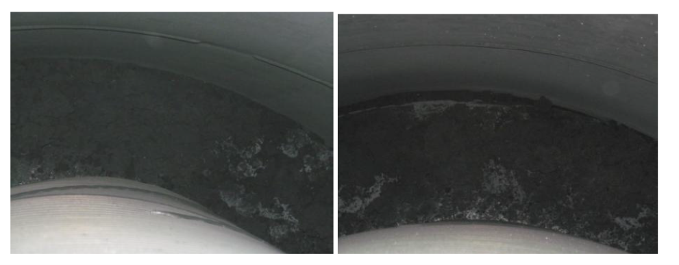
Picture-1: Huge quantity of coke in annular space between reactor grid and shell
Picture-2(a): Last panel of outside reactor grid found fully bulged with huge coke build up
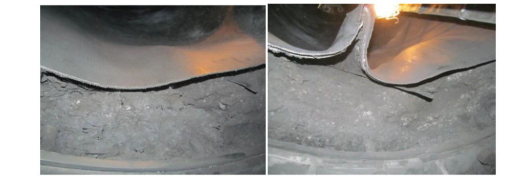
Picture-2(b): Last panel of outside reactor grid found fully bulged with huge coke build up
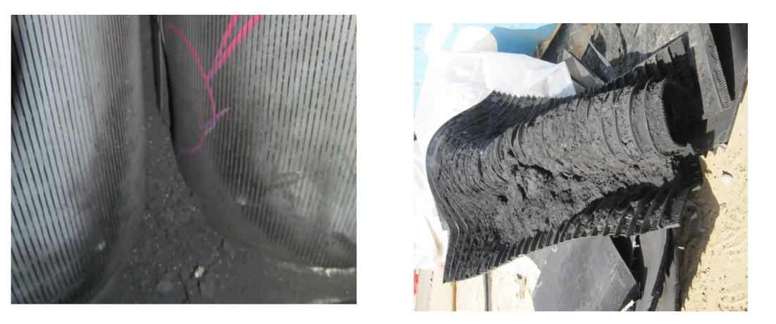
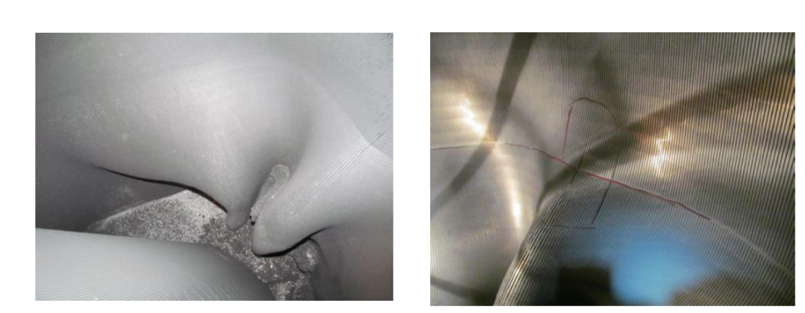
Picture-3(a): Shiny coke between and inside scallops leading to bulging and fish mouth cracks

Picture-3(b): Shiny coke between and inside scallops leading to bulging and fish mouth cracks
A joint root cause analysis with Licensor confirmed presence of Fe and carbon graphite (high carbon content) in the coke samples. During cleaning of the scallops, presence of lot of hard shining coke (metallic coke) was observed along with soft coke. It was concluded that coke build up in reactors/scallops/grids may have taken place due to metal catalyzed coking considering problem with DMDS dosing pump during initial year of commissioning as well as due to other reliability issues like frequent trip of recycle gas compressor. The presence of metallic coke in reactors may have acted as nuclei and further catalyzed the coke growth during recycle gas failure.
The heater tube thickness measurements also indicated some loss of thickness indicating metal catalyzed coking in addition to other forms of coke. The level of thickness loss was fortunately not alarming to inhibit future operation.
Based on root cause analysis certain recommendations were made to minimize metallic coking and damage to reactor internals.
Metallic Coke:
Maintain sulfur level 0.3 to 0.5 ppmw on CCR feed to be substantiated by presence of detectable amount of H2S in recycles gas and 100-150 ppmw of ‘S’ on catalyst sample.
Operate Naphtha Hydro-treating (NHT) unit to remove essentially all of the sulfur and other contaminants in the feed. Inject DMDS in CCR feed through dedicated facility to maintain recommended range of sulfur.
No flame sweeping/scattering on the furnace coils.
Maximum Tube Metal Temperature (TMT) to be restricted below 620oC.
Operation of heater burners within the design regime (maximum allowable process absorbed duty per burner: 1.0 Gcal/h).
Perform positive material identification of tube metal to confirm P9 (confirmed).
Other Coke/ catalyst agglomeration due to coke:
Improvement in reliability of recycle gas compressor.
Check for cold spider legs and try to restore catalyst circulation
Check for quality and temperature of net gas from CCR to avoid condensation in reactor spider legs
Maintain recommended coke ( 4 -5 wt%) on spent catalyst
Stress build up in Reactor internals:
Carry out emergency catalyst circulation in case of unplanned trip of the Recycle Gas compressor to relieve the mechanical stress built up due to difference in the thermal expansion coefficient between catalyst and reactors internals.
Year
2019
Submitter
Process
Question 46: Silicon uptake on hydrotreating catalysts is an increasing problem. (1) What operating conditions favor maximum silicon pickup by the catalyst? (2) Are there differences between silicon from coker antifoamsand other sources? (3) Does the presence of other contaminants such as nickel and vanadium affect the silicon pick-up by the catalyst? (4) What best practices are you using to monitoring silicon pick-up by the catalyst?
James Esteban and Jeff Pro (Criterion Catalysts & Technologies)
Silicon in feed streams to Hydroprocessing units can pose a threat to catalyst performance and must be properly managed. Silicon acts as a poison to the catalyst by depositing on the surface of catalyst particles blocking active sites and reducing critical HDS and HDN activity. Silicon can be found in a wide range of feed streams and is a concern for all hydrotreaters processing naphtha, distillates, and vacuum gas oils. Silicon is present in crude fractions as well as Coker feeds where Si-containing anti-foam additives are widely used. Si from crude fractions is found in higher concentrations in synthetic crudes which have been manufactured at upgrading facilities which employ the use of delayed coking processes that use Si-based anti-foams. Regardless of the source, the methods employed to remove silicon are similar. Synthetic crudes can also contain Si from sand and aluminum silicate clays. In order to properly protect active catalyst beds from Si poisoning consideration must be given to the process conditions, catalyst selection, as well as feed components. In general Si uptake is maximized by operating at temperatures above 550 F with peak uptake performance above 600 F.
For units in naphtha service the temperature regime may limit the uptake capacity of the lead catalyst beds especially when considering units that have low temperature di-olefin reactors. In distillate and heavier service, the typical operating temperature regime is high enough to support maximum Si uptake performance. Another process condition impacting the Si uptake of a catalyst system is space velocity. Units that operate at high space velocities see a lower efficiency in terms of overall Si uptake as a percentage of maximum saturation capacity due to the high space velocity stretching the distribution profile of Si in the catalyst bed.
Catalyst properties such as surface area and particle size play a key role in the Si uptake performance of the catalyst system in lighter feeds like naphtha and distillate boiling fractions. In the gas phase, as in NHT (naphtha hydrotreating) service, catalyst surface area is a critical property that determines the catalysts' ability to uptake Si. Higher surface area catalysts will have a higher Si uptake capacity for NHT service; however, they will typically have less overall HDS/HDN activity due to a limited number of active metals present on the catalyst. This is of particular concern in units that operate at high space velocities with limited catalyst volume. In these cases, dual-function catalysts that have high Si uptake capacity in addition to high HDS/HDN activity can be employed to provide the required balance of Si uptake and activity. In addition to surface area, catalyst particle size is an important factor to consider. In NHT service the rate limiting step is diffusion, which implies that smaller particle catalysts will perform better than larger particle catalysts in terms of Si uptake. The drawback to smaller catalyst particle size is a potential increase in pressure drop.
Units processing distillates benefit from the same catalyst properties but tend to be less affected by space velocity since these units are typically larger and hence have lower space velocities than naphtha units. Distillate units typically processing SR and light coker gas oils also do not have as high a feed Si content as naphtha units (especially naphtha units running high percentages of Coker naphtha). Units processing heavier feeds often contain other poisons such as Ni and V and hence require additional functionality. The catalysts also need sufficient active metals to promote the HDM reactions required for these larger molecules. Ni and V in high concentrations can reduce the Si uptake of trap catalysts; however, the Ni and V uptake is typically of greater concern.
For all applications, care should be taken to apply the appropriate catalysts for the service to optimize metals uptake with activity requirements.
In terms of monitoring Si uptake and performance one must employ a complete cradle to grave approach. Initially the catalyst system must be designed to ensure that there is adequate Si uptake capacity. With limited information in the design stage, employing the use of proper efficiency factors is critical to prevent Si slip to product streams above the desired specification. In some applications Si slip can be absolutely detrimental such as a NHT upstream of a catalytic reformer which uses very costly platinum promoted catalyst that can be poisoned by Si. Alternatively in other processes some Si slip to product is acceptable such as the treating of fractions for the blending of pipeline quality synthetic crudes. It is critical that refiners work closely with catalyst suppliers to ensure that objectives are clear, and the proper approach is applied. It is a best practice to refer to proven commercial performance when designing an optimized system and is best to make use of unit specific performance when available.
During the catalyst cycle, the catalyst activity and Si uptake should be continuously monitored during periodic unit performance reviews. It is best practice to monitor feed Si content using a method such as routine composite samples – these results can be used to calculate a projected Si accumulation which can be tracked against the maximum uptake capacity. Following the completion of the catalyst cycle spent catalyst samples should be collected to provide insight on actual catalyst performance versus predictions as well as to develop a Si distribution profile and material balance across the reactor and validate the accuracy of the composite feed samples. This methodology was well documented in an article – “Estimating silicon accumulation in coker naphtha hydrotreaters.” [1]
[1] Thienan Tran, Patrick Gripka and Larry Kraus, “Estimating silicon accumulation in coker naphtha hydrotreaters”, PTQ, Catalysis 2012.
Brian Watkins and Charles Olsen (ART)
Silicon is probably the most widespread catalyst poison encountered in hydrotreater feeds. The main source of silicon is from delayed coker operations that use an anti-foam agent based on polydimethylsiloxane to suppress foaming in the coker drums. The siloxane complex breaks down in the coking process to primarily cyclic methylsiloxane trimers. These species are volatile at coker temperatures with boiling points ranging from 270-475°F (132-246°C). As a result, these compounds tend to concentrate in the overhead products, and as a general rule of thumb, 70-80% of the silicon at the coker ends up in the coker naphtha fraction. More recently, even refineries that do not have cokers are experiencing silicon poisoning of hydrotreating catalysts once thought unlikely since their feed source comes directly from the refiner’s crude unit. These refineries have begun processing synthetic or other opportunity crudes and the process of making synthetic crude often involves a coking step. In addition, it is becoming more common to use silicon additives in the drilling process, and for pipeline companies to use them for both flows enhancing performance and foaming issues. It has also been found that silicon additives are sometimes used in barge unloading.
In the hydrotreater, the silica fragments from the antifoam agent undergo a condensation reaction with the alumina surface of the catalyst forming a strong chemical bond. Once the silicon is bound to the alumina surface, it cannot be removed by regeneration or other means. It is a more moderate poison compared to contaminants like sodium or arsenic, but it nonetheless results in activity loss of the order of 5-10°F (3-6°C) for each 1.0 wt% Si deposited on the hydrotreating catalyst.
A variety of analytical techniques have been applied to silicon poisoned catalysts, and this confirms that the silicon is associated with the alumina support as opposed to the active metal sulfides of the catalyst. Furthermore, the silicon is dispersed throughout the available alumina surface as opposed to poisoning only the exterior of the catalyst pellet. As a consequence, the available alumina surface area of a catalyst has a significant impact on silicon capacity of a catalyst.
Another important aspect of silicon poisoning is that silicon picks up depends on unit operating temperature. Commercial data clearly show that the operating temperature of the application must be considered when discussing silicon pickup capacity and when designing effective guard catalyst systems. The maximum capacity of the catalyst needs to be considered as well as the capacity at the operating temperatures of the specific unit in order to accurately predict the point at which silicon will breakthrough into the next bed of catalyst or refinery unit.
Accurately measuring silicon in naphtha streams can be done but it takes a bit of work to get a representative sample of the naphtha. The silicon in the coker naphtha depends on the type and amount of antifoam chemical at the delayer coker unit. Delayed cokers have cycles ranging anywhere between 8 – 24 hours. The coker unit is continually producing a coker naphtha stream during these cycles which is typically being sent from the fractionator straight into the naphtha hydrotreater feed drum. The antifoam chemical is usually not added for the entire coker cycle. This means that the silicon in the naphtha stream will vary with the timing of the coker cycle. In order to get a representative amount of silicon in the coker naphtha stream a composite should be made of hourly samples mixed together for the time of the cycle. For example, for an eight hour cycle eight samples would be mixed and the composite sample analyzed for silicon. To measure the silicon an ICP-MS (Inductively Coupled Plasma Mass Spectrometry) instrument can be used. This instrument/method can measure very low metal concentrations.
Year
2014
Process
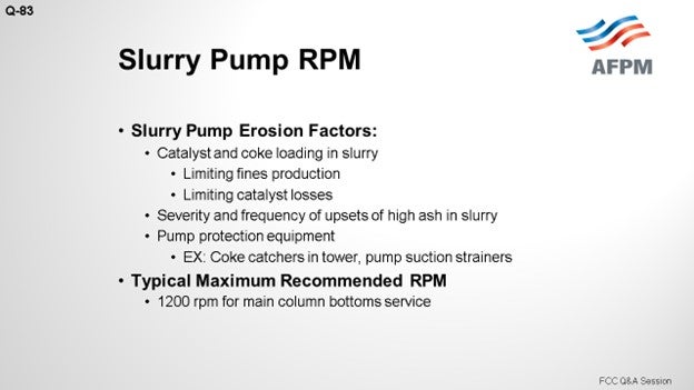
Question 83: Can a slurry pump run at or below 1000 rpm (revolutions per minute)? If not, what is the lowest speed to minimize pump erosion?
RUSSEFF (CVR Energy, Inc.)
The short answer is “Yes”, but it would not be a good FCC answer if I did not say the words, “It depends.” The actual effective service life depends on your solids loading in your slurry system, in both typical and upset conditions. A good set of suction strainers and coke catchers in the entire level will certainly help you. I understand, from at least one of the major licensors, that there is typically a low limit of about 1200 rpm for new units. Can you run lower? Certainly, but there are also some considerations to contemplate.
This slide shows a very old pump life curve from the old Lawrence literature, which I obtained when I was in my position. You can see “1200” annotated in red. You can also see that all of the curves start sloping up and that the coded pumps definitely have a distinct advantage. The CA6NM is uncoded, but it is also represented there without slurry contamination in its process.
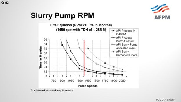
So, can you run lower? Yes. What is not shown up here is the type of contaminant; that is, what was the ash or the BS&W on the particular sample? It does not tell you the nature of the component. Although it is not shown on the slide, we would expect the shape of the curve to be the same. What is also not on the slide and which is part of the “it depends” part is the information about the location of your efficiency on the curve. You know, maybe that does not matter to you, but certainly what does matter are the minimum velocities through your exchangers. So those are some of the other variables to consider. Can you run lower? Certainly. Then you will see some great lifespan there, but it is a balancing act.
SINGH (Indian Oil Corporation Limited)
Slurry pumps are extremely critical for the performance of the MCB (main column bottom) circuit. While it is essential to maintain a certain minimum velocity in the slurry circuit, the speed of the slurry pump is typically governed by the desired capacity, head, and NPSH (net positive suction head). In all of our units, the slurry pumps typically operate between 1100 and 1400 rpm; and in most cases, these pumps are fully lined with 25% chromium (Cr). A word of caution while using fully lined pumps: They are very, very sensitive to thermal shocks. Our experience with these pumps has been extremely good, as far as erosion is concerned. Even under very bad conditions with very high BS&W due to occasional high catalyst carryover situations, these pumps have been able to perform well. But like I said, they are extremely sensitive to thermal shocks, so adequate precautions need to be taken. We have also had some bad experiences caused by thermal shocks to the pumps, which lead to sudden and total failure of the liner.
We have modified the warming up system of slurry pumps to enable heating at a very controlled rate (less than 50°C (82°F) per hour) by mixing hot and cold streams. This has eliminated the problem of thermal shock and substantially improved the reliability of these pumps. A maximum 50°C (82°F) per-hour rate is usually recommended for heating these pumps. One word of caution: It is not only the pump that has to be heated; the suction line or whatever is the stagnant material in the standby pump’s suction line also needs to be heated. Otherwise, whenever the standby pump is put to service, the pump will see an unexpected thermal shock.
ROBERTSON (AFPM)
Those were the responses from the panel. Any comments or questions from Kevin Proops? [Laughter]
KEVIN PROOPS (Koch Industries, Inc.)
I am not selling pumps either. [Laughter] I will put my Pete Andrews hat on here for just a second and talk about fundamentals. Pump rotation speed is important, but it is really the impeller tip speed that will cause erosion. If you slow the pump, you will need a bigger impeller for the same discharge pressure. The curve on Richard’s slide shows 286 feet of head, which is nominally a 100 psi differential. If you really want lower erosion, can you design a system that is more like 50 psi differential? You could put all the heat exchangers in parallel. I have seen that done before. You can avoid high pressure drop control valves in the circuit by diverting the pumparound return to the bottom of the tower to control heat removal, rather than throttling.
I have seen vertical steam generators that basically do not foul. These generators have the channels on the bottom with a vertical bundle. In any design, exchanger tube velocity is important and has been discussed in past sessions. Keep piping runs short. Minimize the pressure drop in the system, and you should be able to get there.
SANJIV SINGH [Indian Oil Corp Ltd. (IOCL)]
Slurry pumps are critical for the reliability of the MCB (main column bottom) system of an FCC unit. Desired velocity in the slurry exchangers also results in a high pressure drop, setting the operational requirement for the slurry pump. Impeller diameter or the speed need to be increased to match the hydraulic requirement of slurry circuit. The speed of the pump is mainly governed by operating parameters such as capacity, head, and NPSH. Adequate minimum tube velocity in the slurry circuit is absolutely essential to avoid excessive fouling in these exchangers. In the case of slurry pumps, a lower speed will mean less erosion but will require a bigger pump size. A higher head will require a higher speed. A speed limit of about 1500 rpm has been specified typically for FCCU units. Degradation of pump performance will increase the rate of exchanger fouling and limit MCB heat removal. To minimize pump erosion from catalyst and coke particles, an API fully lined pump is often required when operating with a higher pump head and operating speeds in the MCB circuit.
Apart from lowering speed, another way of reducing erosion is to specify a fully lined slurry pump with a 25% Cr iron liner. These pumps can be operated continuously for a considerably longer period compared to a normal API pump. In all of the recent projects, licensors specified fully lined slurry pumps and the same were used with satisfactory performance. Of course, speed was also limited, but physical pump availability at that speed has to be ascertained.
For most of our FCC/RFCC units in IOCL, slurry pump speeds are in the range of 1100 to 1400 rpm. Even for this operating range, fully lined pump internals are used (25% Cr). Though these pumps have demonstrated reasonable resistance to erosion, but these pumps remain extremely sensitive to thermal shocks. Recommended warming or heating up procedure for these pumps should be strictly followed. In our newer units, we have installed facility to heat up these pumps in a very controlled manner by mixing two streams of different temperatures and fine controlling the heating rate. Further reduction of pump speed below 1100 rpm is also possible considering acceptance of the bigger size of the pump model, as well as the availability of the PTR (performance track record).
Erosion is no doubt a function of speed: the higher the speed, higher the erosion, which will require more frequent overhauling.
CHRIS STEVES (Norton Engineering)
Slurry pumps are designed to operate at low speed to minimize corrosion but trade off hydraulic efficiency to do so. Pump manufacturers with long-term slurry experience can provide proven erosion-resistant metallurgy options (casing, liner, wear rings, etc.), which allow operation of slurry pumps at relatively high speeds (1200 rpm typical) yielding hydraulic efficiency and ultimately power reduction benefits versus low speed pumps.
ANDREW W. SLOLEY (CH2M HILL)
Refiners have reliably run API pumps continuously at speeds of 900 rpm and below. The lower speed is often compensated for by using a larger impeller. Slower pump speeds are applied in most cases to reduce suction-specific speed problems. However, slower speeds also reduce erosion, as well as reducing discharge pressure and pump efficiency.
Year
2015
Process
Question 37: To help manage fouling and pressure drop in a naphtha hydrotreater, do you rely on graded bed technologies or feed filtration (magnetic or other) or both? What is your experience with these options? What other means are being employed?
Olivier Le-Coz (Axens)
The countermeasures to pressure drop build-up in naphtha hydrotreaters units obviously depend on the cause of the fouling. The two main causes that we know in Naphtha HDT units of are corrosion particles usually coming from outside the battery limit and gums or coke. Axens addresses those two issues at design stage.
Corrosion particles are a potential problem and we indeed address that by implementing both feed filters and grading beds. Feed filters are specified as mechanical filtration devices, usually using metallic cartridges. We don’t have experience with magnetic filters.
As regards grading, Axens uses in its new unit's design or in catalyst replacement loading diagrams a wide range of products from inactive and high void fraction materials to lower void fraction and active products which can also address the removal of specific contaminants. Grading materials have proven to be efficient against particles in many cases. Grading arrangement can be studied on case-by-case basis and when relevant. Axens can propose arrangements of newer generation high void fractions and various pore size materials called CatTrap.
The gums and coke is a problem with units treating olefin and especially diolefins rich feeds from FCC or Coker Naphtha. The important considerations when designing a unit to treat such feedstocks are:
- avoid storing these materials but treat them directly from fractionation columns.
- foresee the injection of an antioxidant chemical if storing cannot be avoided.
- avoid hot spots in the heating system that would cause diolefins to polymerize, optimize the feed preheating scheme to avoid the use of a fired heater, or to reach the full vaporization point ahead of the heater.
But the most efficient way to stay away from gums pressure drop issues is to implement a selective hydrotreating reactor upfront the main HDT reactor. At low temperature and using a dedicated selective hydrotreating catalyst this pre-treatment reactors eliminates the diolefins without giving them a chance to coke further downstream in the process in the heater or at the top of the main and more active HDS catalyst which operates at higher temperature. Axens has been successfully applying this philosophy in many Coker Naphtha and FCC Gasoline (PrimeG) units. We have successfully revamped diolefins rich Naphtha HDT units with addition of a selective pre-treatment reactor, achieving a dramatic decrease of the downstream equipment fouling rate.
Ujjal Roy (Indian Oil Corporation)
We have much naphtha hydrotreaters (NHT) in our ten refineries, some operate with total straight run naphtha and others with cracked gasoline varying from 10% to 40% in feed. In many of the hydrotreaters, we have experienced run length limitations due to high-pressure drop-in reactors or pre-heat circuits while the catalyst was still active for continued operation. Depending upon the basic design, source of feedstock and its composition, we have feed filters (magnetic or cartridge or candle) in all NHT along with graded bed in few of them.
In one of our NHT processing 40% FCC gasoline, we have both magnetic feed filter and graded bed. But even in this unit, we have experienced pressure drop problem in CFEs due to caustic carry over from up-stream FCC unit. In another unit, where we have added graded bed 3 years back in addition to cartridge filter in feed, we have observed increased run length after addition of graded bed. In another unit, in which we have basket and cartridge filters in series but no graded bed, we had to do three skimmings in four years’ operation. The feedstock for this unit is straight run naphtha comprising about 30% material transported from other refinery by tank wagon. We have, off late, replaced the transportation from tank wagon to pipeline and directionally there is improvement in pressure drop, perhaps due to reduction in oxygen and iron pick-up from tank wagon. In another unit, processing about 10% FCC gasoline, having both cartridge and magnetic filter but no graded bed, skimming had to be done five times in six years. The reasons for the high pressure drop as observed after opening of the reactor bed is found to be central hip created at catalyst top bed. This may be due to some design deficiency. In all our hydrotreaters where we are processing cracked gasoline, we directly route the gasoline to hydrotreater with provision of intermediate balancing tank. All these tanks are nitrogen blanketed. Also, in one of the refineries, we inject antioxidant stored in the tank.
General causes contributing to pressure drop in hydrotreaters are either iron scales or coke/polymers. Iron scales are carried with feed from up-stream equipment like tanks and piping. Magnetic and other filters would be helpful in arresting foulant coming from up-stream units and tanks. Coke and polymers come from CFEs and charge heaters. High olefin content in feed than design and dissolved oxygen picked up during storage will aggravate pressure drop. In some case, we have observed high sodium content in the crusts formed on top bed. The source of sodium is likely carry over from up-stream unit. We have taken additional operating measures in up-stream unit to arrest sodium carry over.
In many instances in hydrotreaters, we have observed spikes in Delta P after restart of compressor subsequent to its tripping. It is suggested by our licensor that this might be due to two phase flow at the start of the compressor carrying coke from CFEs and charge heater to reactor. To avoid two phase flow, they recommended to reduce reactor pressure considerably when starting the compressor and to increase the reactor pressure only when reactor attains 260°C and above.
Where we have coker naphtha in feed, in one of the hydrotreaters, multi-layer grading beds have been used. The selective hydrogenation upfront also acts as guard to hydrotreater.
Most of the pressure drop problems in hydrotreaters are unit specific and might have been overlooked in design stage. Preventive measures can only be determined through careful studying the problem over run length.
Brad Palmer (ConocoPhillips)
ConocoPhillips generally uses graded beds on all our hydrotreating units. Several units also have feed filters. The graded beds are usually adequate for all but the worst cases, in spite of precautions. We have experienced extreme cases of upstream corrosion that have forced us to occasionally skim reactors and clean preheat exchangers, in spite of precautions. The upstream problems were eventually corrected by alloy or chemicals, although we prefer to avoid too many chemicals in the naphtha feeds. The difficulty with iron sulfide in units is that the particles can be extremely small (< 1 micron), so filtration is not always effective. Filtration for the naphtha units is usually cartridge filters.
Another more frequent cause for fouling in our system is polymerization of cracked feed stocks. This is promoted by exposure of the feed (or any feed component) to oxygen in tankage but can also be caused by numerous other polymers initiating factors. Filtration is not often effective at removing the polymers, except for those gums already formed in tankage. Additional polymers form rapidly during preheat, downstream of any filtration. The polymers or gums will foul the preheat exchangers, fired heater and the reactors, if they make it that far. To manage polymers in a naphtha hydrotreater, we prefer to add antioxidant to the cracked stocks as they rundown to tankage and add anti-polymerants to stocks as they are feed to a unit. The chemicals help mitigate polymerization, but do not completely prevent it. We also make sure that the dry point of the feed is reached ahead of the fired charge heater to prevent polymer lay down in the heater, subsequent coking, and potential tube failure.
Erik Myers (Valero)
Valero uses the following key approaches:
1. Filter the feed
2. Aggressively use grading material as our naphtha hydrotreaters are not activity limited
3. Utilize mechanical solutions where they look to be effective, such as trash baskets or pressure drop reducing inlet trays.
A key operating area to focus on is avoiding two phase flow in the charge heater. Liquid in the charge heater can lead to coking which when thermally cycled will transfer this coke to the reactor. Similar transfers of iron scale can take place with upsets in any upstream fractionation towers or other equipment.
This topic was also covered in detail in last year’s Q&A (Gasoline question #35). I recommend referencing the transcripts from that review for more information.
At least one of our sites has had very good success with a chemical treatment program incorporating dispersant and antioxidant components to significantly extend the run length of the feed – effluent exchangers. Feed effluent exchanger fouling was also covered in depth as question #36 from the 2010 Q&A session. The 2010 answers for gasoline and FCC naphtha hydrotreating also provide good information on the impacts of olefins and feed gum and polymerization impacts.
Year
2011
Process
Question 32: What is your suggested minimum temperature required to achieve adequate metals removal in the demetalization (demet) catalyst to protect primary treating catalyst in FCC and hydrocracker pretreaters?
TEMME (Albemarle Corporation)
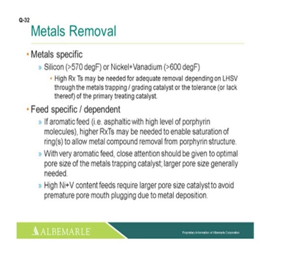
The suggested minimum reactor temperature required for adequate metals removal is going to be metals specific. For silicon, the temperature is definitely greater than 570°F; and for nickel and vanadium, we suggest greater than 600°F. Now higher reactor temperatures may be required for adequate removal, depending on the space velocity through the metal-strapping catalyst and whether or not there may be a tolerance issue with the primary treating catalyst. It can also be very feed specific. If it is a very aromatic feed, such as a highly asphaltenic feed with high levels of porphyrin molecules, higher reactor temperatures may be needed to enable saturation of a ring(s) of the porphyrin structure to allow for the metal compound removal.
With very aromatic feed, close attention should be given to an optimal pore size of the metal-strapping catalyst with a larger pore-sized catalyst generally being needed. High nickel and vanadium content feeds require such a catalyst to avoid a premature form of plugging due to the metal deposition.
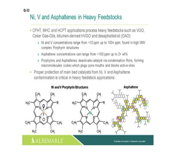
For hydrocracker pretreating's and other gas oil-types of processing applications, especially when processing heavy feedstocks, not only is nickel and vanadium problematic, but also the porphyrins and the asphaltenes. These molecules can deactivate the catalyst via a condensation reaction forming coke that is going to plug up pore mouths and block access to active sites. So proper protection of main bed catalysts for not only nickel and vanadium, but also for asphaltene contamination, is critical in heavy feedstock applications.
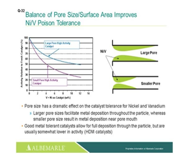
The left corner of this slide shows a comparison, in terms of large pore-sized catalysts versus small pore-sized catalysts, with the Y-axis showing the relative activity of the fresh catalyst as nickel and vanadium as deposited on the catalyst, which is the X-axis. You can see that the falloff and activity with the small-pore high activity catalyst can be much greater than that of the large-pore high activity catalyst. The graphic to the right really depicts this type of phenomenon where the larger pore catalyst allows for a fuller deposition of metal throughout the catalyst particle; whereas with the small pore-sized catalysts, there is pore-mouth plugging which restricts access to the active site. So, a good metal-tolerant catalyst is definitely needed for this full deposition of the metals through the catalyst particles. Now yes, there is usually some tradeoff in terms of a little lower activity; so, you definitely must have a good balance between your demet (demetallization) catalyst and your active catalyst to make sure that you have enough demet catalyst to protect your active catalyst.
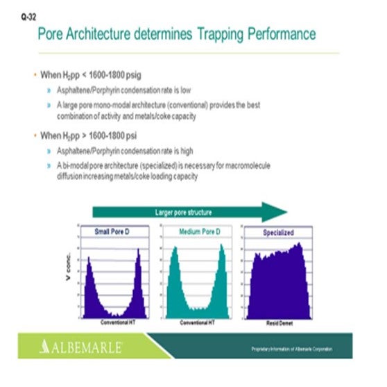
Just one other slide relating to asphaltene porphyrin condensation potential. The hydrogen partial pressure unit is below 1600 psig. A large-pore monomodal architecture type of catalyst, a conventional catalyst, is probably just fine for activity, as well as metals coke capacity. But for higher hydrogen partial pressure greater than 1600 where the condensation rates become higher, bimodal architecture specialized catalysts can be very helpful in terms of increasing the metals- and coke-loading capacity.
MORELAND (Valero Energy Corporation)
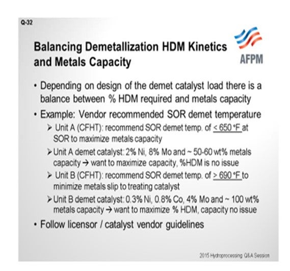
Thanks, Paul. That was a good summary. I told the guys at lunch today that we get a lot of the basics in this Q&A, and I think Paul covered really, really well the basic mechanisms in nickel vanadium plugging. So I will just bring a question to the audience describing a scenario I have seen while helping support our units within Valero. Some recommendations from our catalyst partners are a little different. We have two cat feed hydrotreaters – and this is for you experts in the room – that have two different recommended minimum temperatures for demetallization. Basically, this question asked about cat feed hydrotreaters and hydrocracker pretreats. Unit A is a cat feed hydrotreater for which our vendor recommended the demet temperature should stay below 650°F at start-of-run. I have a very similar unit in another one of our refineries. A different catalyst vendor recommended the start-of-run demetallization temperature be greater than 690°F. So, in one case, they say less than 650°F; and in the other, greater than 690°F. As I reviewed this issue more in-depth, I looked into the catalyst properties themselves. What we have found was that in Unit A, the catalyst itself that they were using in the demet beds was 2% nickel, 8% moly, and an expected 50 to 60 wt% (weight percent) metals pickup. So, my theory – and correct me if I am wrong – is that our goal here is to maximize the capacity of this demet catalyst. We are not really worried about the percent of nickel-vanadium removal. The second unit: You can see that the metals here were basically about half of what they were in the other. We are looking for almost twice the weight percent metals pickup. This is the one they recommended 690°F as the minimum operating temperature. The idea here is to try to maximize the nickel-vanadium removal and protect the downstream catalyst so that the capacity really would not be an issue. So, at the end of the day, when they asked me this question, I said, “Go back to your licensor or catalyst vendor and do what they say.” [Laughter]
EPSTEIN [Flint Hills Resources, LP (FHR)]
A tough act to follow. Flint Hills Resources Pine Bend Refinery has typically used around 500 to 550°F as a minimum temperature for treating. The minimum temperature required for metals removal depends on the metals that are present in the feedstock. Arsenic removal follows a kinetic reaction (chemically bonding to the catalyst) and therefore may require a higher temperature to maximize pickup than other metals, such as nickel, vanadium, and silicon. For specific poisons and catalysts, FHR would usually defer to the supplier. The people who provide the catalyst-supplier guidance are in this room. I am not going to name names, right? [Laughter]
RAMÓN LOUREIRO (KBC Advanced Technologies, Inc.)
Is the loaded density the same in both cases?
MORELAND (Valero Energy Corporation)
No, I do not believe it is. I think the demet catalyst in Unit B with the lower metals is about half of the loading density.
RAMÓN LOUREIRO (KBC Advanced Technologies, Inc.)
If one is half of the other – that is, 50 units per volume – and the other one is 100 units per volume, then you will end up with the same result, given that one loads twice the metals on a weight percent basis, right? Then it is independent of space available in the reactor to load the catalyst.
MORELAND (Valero Energy Corporation) You would end up with them, yes.
RAMÓN LOUREIRO (KBC Advanced Technologies, Inc.)
And it does not matter how much space you have to put in the catalyst?
MORELAND (Valero Energy Corporation)
That is true. I do not think it is a 2:1 ratio, but there is a density difference between the two.
PAT GRIPKA (Criterion Catalysts & Technologies)
Our recommendation, if you want to maximize the metals uptake, is to operate at a lower temperature and minimize pore mouth plugging, especially at the beginning. If you want to maximize removal of HDM (hydrodemetallization), you will want to operate at a higher temperature to increase the percent HDM. But your overall capacity through the whole cycle will be less because you will have increase pore mouth plugging, which was shown quite well by the first slide. So there are competing reactions and competing objectives, but we can work with either and design a system properly for either one.
MICHAEL SCHMIDT (Haldor Topsoe, Inc.)
The metal capacity of a hydrotreating catalyst is mainly determined by the catalyst’s porosity and thus not dictated by the temperature. However, the rate of metal removal is a catalytic reaction and is therefore very much dependent on the reactor temperature, as well as catalyst activity and residence time (LHSV). Based on experience, it is advisable to have reactor temperatures above 600°F to ensure that the rate of demetallization is high and the demet capacity of the catalyst is properly utilized. A higher metal content in the feed will results in higher metals pick up capacity for the catalyst.
DORIAN RAUSCHNING (Criterion Catalysts & Technologies)
The rate of feed metals removal and a catalyst’s capacity to trap metals, such as Ni and V (vanadium), in FCC PT (pretreat) feeds depends on temperature, pressure, feed metals concentration, catalyst pore structure, and catalyst size. In general, the higher the temperature, the higher the rate of HDM, but a minimum temperature of about 600°F should be maintained. Criterion’s demet catalysts contain moderate hydrogenation activity that generates exotherms and provides some additional driving force for the HDM reactions to occur, even with a suboptimum reactor inlet temperature. Other feed metals – such as Si, As, or Fe (silicon, arsenic, or iron) – can also be present and be removed from the feed by selective trap catalysts in this temperature range. Criterion offers a wide range of selective Ni, V, As, Si, and Fe trap catalyst whose depth, sizes, and properties can be optimized to remove metals from feed and protect the primary conversion catalyst.
Year
2015
Process