Question 31: What is the threshold concentration of arsenic and phosphorus requiring a dedicated trap system? How are the arsenic and phosphorus trap systems specified,and what are the controlling mechanisms?
WATKINS [Advanced Refining Technologies (ART)]
Arsenic is a big concern because it is a permanent poison that causes fairly significant activity. We generally see around a 60° Floss per weight percent pickup; so you will want to pay attention to it. As a side note, it is also common in most fractions of hydrotreating: so anything from naphtha to heavy gas oil. Since there are a large number of process variables, catalysts, and operating conditions, the level that would define where a dedicated trap is actually needed will really depend on how much arsenic is coming into your reactor and possibly what other catalyst is present there as well. Generally, we like to monitor how many pounds of arsenic per day are coming into your hydrotreater; then, we look at the controlling mechanisms for deactivation.
The chart on the left side of the slide compares relative arsenic pickup on the catalyst to the actual amount of nickel present in the reactor. One of the major factors for how much arsenic your reactor can hold is how much nickel is sitting at the top of your reactor, or even in the whole reactor. So, as you go from left to right, you can see you can pick up quite a bit more arsenic.
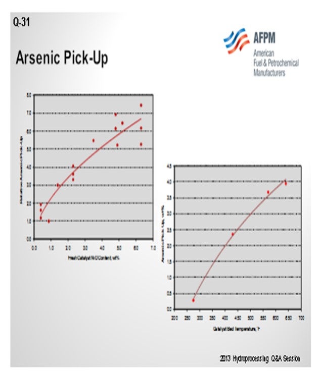
What also controls arsenic pickup is the operating temperature of your hydrotreater. You can generally look at the weighted average bed temperature or the actual temperature of where the catalyst is located. Something like a diolefin reactor down at 250°F to 300°F will pick up a very low level of arsenic. Whereas if you get up into the 650°F to 700°F range, that same catalyst can pick up a significant amount if it is in the right location. So, these two factors will really define how much volume we need to place, in terms of a guard catalyst in your reactor.
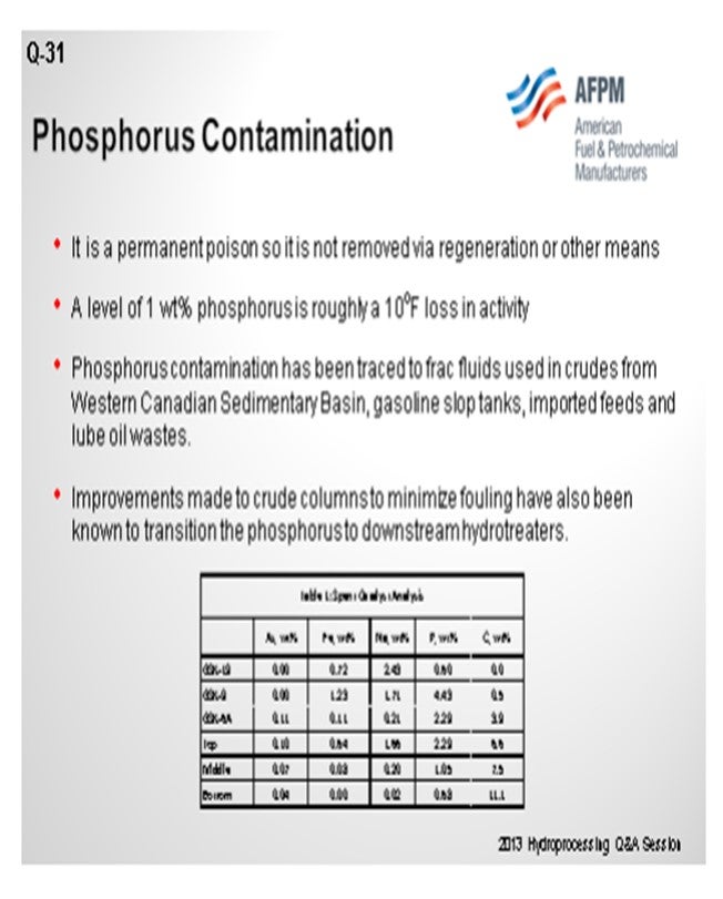
With phosphorus, there is the same problem. In this case, at about 1 wt% (weight percent) pickup, we see somewhere in the order of 10°F loss in activity. That number goes up as you get significant levels of phosphorus on the catalyst, but the first amount is not necessarily as important. On the bottom of the slide is a table showing a spent catalyst analysis from a reactor. You can see that this unit was able to pick up phosphorus even on some of our guard material. So, in some of our rings and support, you can actually pick up quite a bit of phosphorus. Again, that is related to temperature. It is also related to alumina surface area, similar to silicon trappings. So that should be your focus. Really, the amount of catalyst in your hydrotreater will determine where you define your need for dedicated trap material. We recommend spent catalyst analysis for looking at things like that.
SIVADASAN (UOP LLC, A Honeywell Company)
Arsenic is a poison for hydroprocessing catalysts and tends to be specific to crude sources. We have seen that how they apply to catalysts is mainly determined by the type of reactions being carried out. So for example, in a ULSD (ultra-low sulfur diesel) unit, if you see where an indirect hydrogenation route is the preferred part, then concentrations as low as 500 to 1,000 ppm (parts per million) of arsenic can affect the activity of the catalyst by more than 50%. But in a unit that is processing around 500 ppm of diesel, the catalyst will be able to withstand up to 1 wt% of arsenic before you see a 50% reduction of the life. Due to the broad range of arsenic concentrations, electro, and cycle lengths, we believe that it is not possible to confidentially cite a specific threshold concentration above where its dedicated arsenic trap system may be required.
Phosphorus, again, can enter into the hydrotreater unit from various sources like crudes, drilling fluids, and phosphated trendsetters. They are the same biofeeds. We believe that the phosphorus generally tends to be quite similar to the sodium. Around 1 wt% of sodium may affect the activity of the catalyst by more than 50%. The catalyst performance and maximum allowable limit are highly dependent on the source and form of the phosphorus.
MUKESH PATEL (Reliance Industries Ltd.)
What is the Best Practice for analyzing arsenic and phosphorus? Should it be done weekly or on some other frequency? Because arsenic is very important when the crudes are changing every now and then, what should be the frequency and what is the industrial experience?
SIVADASAN (UOP LLC, A Honeywell Company)
The determination of arsenic is a bit difficult, as you pointed out, because it interferes a lot with the lab analysis. What people generally do is run a cycle, do a spent catalyst analysis, and then back-calculate how much amount of arsenic is in the feed.
MUKESH PATEL (Reliance Industries Ltd.)
When we say spent catalyst analysis, it is some sort of analysis of used catalyst, right? But what is a better predictive estimate we can do? Because when you want to capture, you can decide on some limit on the arsenic and then put in an arsenic trap. But if you keep putting on an arsenic trap, you will ultimately have a challenge because you will be compromising on cycle life. What I mean to say is that spent catalyst analysis is done after the completion of the cycles, which tells you what the true level of arsenic was in your feed. For example, suppose you are deciding about some loading for the new cycle and how to capture arsenic. Once you start putting in more and more arsenic traps or any demetallizing catalyst, you will be compromising the cycle because your volume will be less in the main catalyst. So, has there been any development where the conventional arsenic traps have a certain capacity for absorbing the arsenic? Is there any new development to help us capture three or four times the arsenic with the same type of volumes?
WATKINS [Advanced Refining Technologies (ART)]
The amount of trap will really depend on your main bed catalyst and your guard catalyst up at the top. If using a high-nickel catalyst, you could actually trade off and balance that activity; so you will maximize your cycle. If you have nickel catalyst in your entire reactor, you could extend your cycling because you can actually pick up a lot more arsenic that way. It is a constant battle, though, to define your cycle length and the amount of arsenic you can pick up. It is all dependent on temperature and how many pounds per day you are going to put in. I recommend that you work with your catalyst supplier to figure out an optimum system and what their products can actually hold without losing any activity or cycle length.
BRIAN WATKINS [Advanced Refining Technologies (ART)]
Arsenic
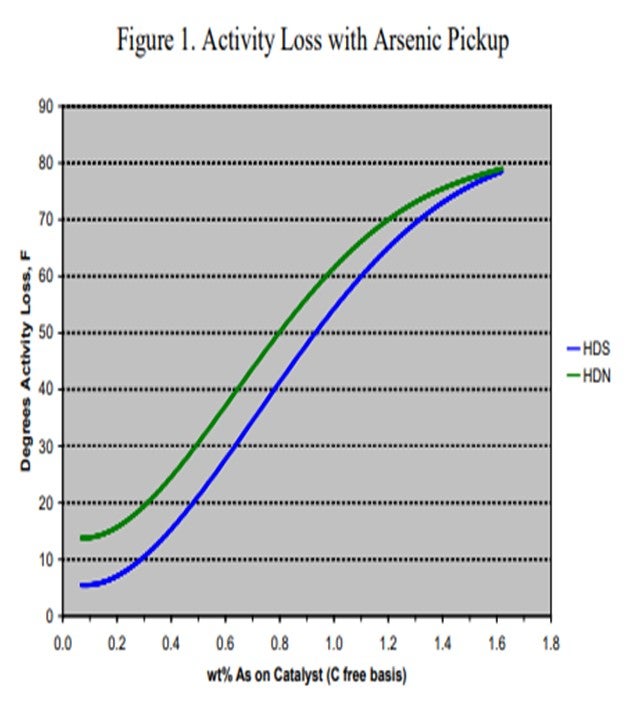
Arsenic (As) is found in many crudes including some from West Africa and Russia, as well as many synthetic crudes. It is becoming a common contaminant as use of these crudes, especially synthetic crudes, has been increasing in recent years. The arsenic is believed to bind with the metal sulfide sites (and in particular, the active nickel on the catalyst) forming nickel arsenide. This has a dramatic impact on catalyst activity. To demonstrate the effect of arsenic on catalyst activity, ART obtained a series of spent catalysts containing different levels of arsenic. These samples were carefully regenerated in the laboratory and were then activity tested using a diesel feed containing 50% cracked stocks under conditions producing less than 500 ppm sulfur. Figure 1 summarizes the results of that work. At 1,000 ppm, arsenic on the catalyst shows 5°F HDS (hydrodesulfurization) activity loss and nearly 15°F loss in HDN (hydrodenitrogenation) activity. The activity loss quickly increases to over 50°F with 1 wt% arsenic on the catalyst.
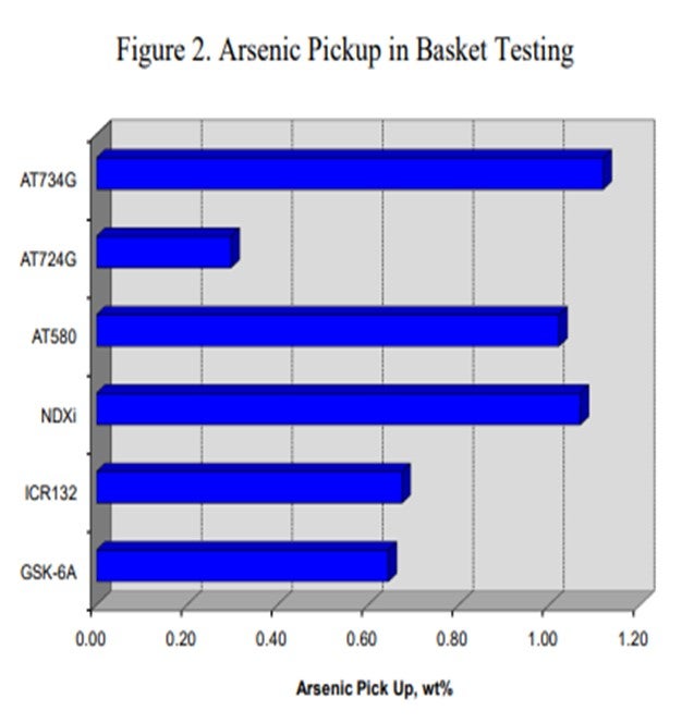
Canister data for a variety of catalysts also indicates that catalysts containing nickel are more effective for trapping arsenic. Figure 2 summarizes the arsenic pickup values for several NiMo (nickel molybdenum) catalysts. As this data shows, both high metals ULSD catalyst NDXi and AT580 as compared to our recent guard catalysts AT724G and AT734G, which are quite effective for trapping arsenic. The data also indicates that the active ring materials and demetallization catalysts used are also effective for trapping arsenic.
Other canister data also shows that the ultimate arsenic pickup is heavily dependent on temperature. Figure 3 shows the arsenic pickup as a function of temperature for a NiMo catalyst. These results were obtained by analyzing spent samples of a high metals NiMo catalyst from a three-reactor unit processing 100% cracked naphtha from a synthetic crude source. The first reactor was operated at very low temperature (about 275°F) in order to saturate diolefins. The second reactor was designed to saturate mono-olefins and operated at about 430°F. The last reactor had an inlet of 570°F and an outlet temperature of approximately 650°F. The arsenic content on the catalyst correlated with the temperature of the reactor as depicted in the figure. The data demonstrates that a high nickel catalyst can pick up very high arsenic levels if the operating temperature and feed concentration are high enough.
Noting that there are a wide range of arsenic levels, unit operating conditions, and expected cycle lengths, the ability to define a single-set threshold for when a trap is needed is difficult. It is recommended that if arsenic is found to be a problem contaminant, you will need to consult your supplier to determine if it is impacting the cycle and if and how much guard catalyst is needed.
Phosphorous
Phosphorous contamination in oil has been traced to fracturing fluids that are often used in crudes from the Western Canadian Sedimentary Basin. The source is diphosphate esters which are soluble in the crude oil. Refineries that run large percentages of light Western Canadian crude have reported crude column and crude furnace fouling for many years. Improvements made to crude columns to minimize fouling have transitioned the depositing of phosphorous to the downstream hydrotreaters.
Other sources of phosphorous include gasoline slop tanks, imported feeds, and lube oil wastes. If phosphorous does manage to make its way into the hydrotreater, it will poison the active sites of the catalyst causing a loss in activity. A level of 1 wt% of phosphorous on the catalyst results in roughly 10°F loss in activity. ART recommends that a feed content of less than 0.5 wppm (weight parts per million) be maintained whenever possible, as well as the use of feed filters to assist in trapping of phosphorous sediment.
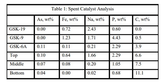
An ART catalyst case study of the detrimental impacts of feed poisons on hydrotreater performance involved a ULSD unit which had recently started up with ART catalysts. Shortly after startup, the unit began to experience extremely rapid catalyst deactivation. It was so severe that within a couple months, the unit required an unplanned turnaround and the installation of fresh catalyst. Samples of spent catalyst representing the whole catalyst charge were collected and analyzed in the laboratory. The results are summarized in Table 1. It is apparent from these results that the catalysts were exposed to high levels of several poisons including arsenic, sodium, phosphorous, and iron. The contaminants penetrated well into the catalyst bed. Catalyst at the bottom of the reactor was not yet poisoned, but the coke content was extremely high for catalyst which had been onstream such a short time. The level of contaminants indicates the catalyst in the top half of the bed lost over 60°F of activity while the bottom was providing most of the HDS conversion. This required very high temperatures, which is reflected in the high carbon content at the bottom of the bed.
ART has a suite of options in order to protect the main bed from these and other contaminants which may be present in the feed to a typical hydrotreater. The use of several of these materials combined together can adequately provide protection and extend the cycle life of your hydrotreater.
RAJESH SIVADSAN (UOP LLC, A Honeywell Company)
Arsenic (As) is a very potent poison for hydroprocessing catalysts. Although As tends to be limited to specific crude sources (e.g., crudes from the U.S. and Canadian Rocky Mountains, Russian Urals, specific Chinese and West African sources, and “synthetic crudes” from Canada and Venezuela), it is usually present in all boiling fractions of those crudes.
Arsenic tends to poison the nickel sites of hydroprocessing catalyst, and the amount required to reduce catalyst activity by ≥50% depends strongly on the type of reactions being catalyzed. For instance, in diesel hydrotreating where ULSD is produced and product quality depends heavily on hydrogenation route desulfurization, as little as 500 to 1,000 wppm arsenic on catalyst can reduce HDS activity by 50%. On the other hand, for hydroprocessing applications where direct desulfurization is the primary mechanism for reaching product targets, higher levels of arsenic contamination on catalyst (about 1 wt% As) may be tolerated while retaining HDS activity greater than 50% of fresh catalyst activity.
Because of the broad range of as concentrations on catalyst that will poison the catalyst, as well as the broad ranges of LHSVs (liquid hourly space velocities) and cycle lengths for various hydroprocessing applications, UOP believes it is not possible to confidently cite a specific threshold concentration for as in feed above which a dedicated as trap system is absolutely required.
Phosphorus (P) can enter the hydrotreater feed from numerous sources: crudes, drilling fluids, phosphated ZSM (Zeolite Socony Mobil), phosphorus-based corrosion inhibitors and flow improvers, and biofeeds.
In one UOP commercial experience, about 3 wt% phosphorus on the catalyst terminated all the exotherm in the catalyst bed. Organic phosphorous can penetrate into catalyst pores. In general, our understanding is that the poisoning is similar to sodium where about 1.0 wt% concentration reduces the catalyst activity by 50%.
Based on UOP’s experience, we have found that the quantitative effects of phosphorus on hydroprocessing catalyst performance and the maximum allowable level are highly dependent on the source and form of the phosphorus compound, catalyst properties, and the process application, which all need to be considered when designing a trap system. Thus, UOP believes it is not really possible to confidently cite an absolute threshold concentration for phosphorus in feed above which a dedicated trap system is definitely required.
PER ZEUTHEN (Haldor Topsøe, Inc.)
Arsenic and phosphorous compounds are both known as permanent catalyst poisons; however, they each have very different deactivation mechanisms. Arsenic species found in the crude oil, particularly in the heavy ends, act as a true catalyst poison during titration of the nickel- or cobalt-promoted catalytically active sites. Although the concentration typically is rather low in ppb (parts per billion) levels, content of more than 50 ppb, for example, will have a significant negative impact on the catalyst performance. Arsenic compounds are very poisonous to the working catalysts, a typical high-activity catalyst has lost most activity after accumulation of as little as 1% As. Besides, shale oil and other new crude types (Russian and Canadian crudes) contain significant arsenic levels.
Haldor Topsøe has developed a number of dedicated arsenic pickup catalysts to protect the downstream bulk catalyst from very severe poison. The arsenic pickup capacity of this catalyst, TK-45, is as high as 10 wt%, but the actual pickup capacity will depend on the arsenic level in the feed and the operating temperature. With improved diffusion and preparation, Topsøe has recently launched a new dedicated arsenic trap, TK-49, with improved arsenic pickup for all hydrotreating applications.
Phosphorous species are rarely found in typical crudes; however, some opportunity crudes (and in particular, renewable feeds) often contain significant amounts of phosphorous. Moreover, phosphorous containing anti-corrosion additives can be found in the diesel and VGO (vacuum gas oil) fractions. The phosphorous compounds are decomposed in the hydrotreater, and the phosphates react with the alumina support, forming very stable alumina phosphates. Accumulated amounts of phosphates will reduce the accessibility to the active sites of hydrotreating catalysts and lower the activity accordingly.
Topsøe has a specialty product, TK-31, with a capacity of more than 5 to 6 wt% phosphorus, where reaction sites for phosphates have been improved the most. Topsøe recommends installing this phosphorous trap if the feed level is higher than 2 ppm phosphorus for protecting the downstream bulk catalyst from contamination.
Year
2013
Process
Question 99: Tight oil-derived FCC feeds are known to contain high levels of contaminant iron (Fe) and calcium (Ca). What catalyst design features are important for minimizing their effects? What level of these contaminants can be tolerated? What lab procedures can accurately simulate Fe and Ca contamination?
KOEBEL (Grace Catalysts Technologies)
There are a lot of parts to this question, so I will respond to them independently. One of the catalyst design features that is important in any kind of feed, when you are going to get high iron and high calcium, is in the porosity. We talked a little before about how these contaminant metals tend to form these eutectics which can melt the surface of the catalyst and close off the pores. So having the right pore size distribution and mesoporosity in your catalyst is tremendously important. It is also really critical to look at the pore size distribution, not just the total pore volume; because in certain instances, you can have pore volume that measures consistently from catalyst to catalyst despite the difference in the pore size distribution. So I am sure all of the catalyst vendors will agree that the pore size distribution is a tremendously important piece of this puzzle.
This slide shows an example of a commercial unit into which Grace put a MIDAS® catalyst. As I mentioned before, MIDAS® is a catalyst with which we take great care to optimize the pore volume and mesoporosity of the catalyst system. This particular unit ran relatively high iron plus calcium; and by putting higher mesoporosity into the system, we were able to help with the bottoms yield.
The question also asked about lab procedures we have found that simulate iron and calcium tolerance. Actual impregnation of iron and calcium on a fresh catalyst for lab deactivation is relatively difficult to accomplish. It is an ongoing area of research at Grace, but it is not one where we have found that the surface changes that happen to the FCC catalyst are easy to simulate in the lab. However, we do have a good test for actually measuring e-cat diffusivity. That test involves inverse gas chromatography where you take a gas chromatograph tube, pack it with FCC catalysts, and run a spike of a probe gas into it. If the FCC catalyst has a lot of diffusivity inherent in it, the probe gas will diffuse into and out of the catalyst sample that is in the chromatograph tube. It takes longer for the probe gas to come through in a more drawn-out profile on the other end, so you can measure the actual porosity of the catalyst sample quite well.
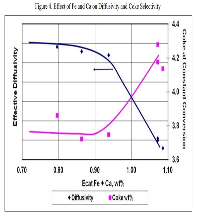
The next slide displays an example of the data from that type of testing and is representative of what we see across most samples. The blue line represents the effective diffusivity of the catalyst. As you pile on iron plus calcium, the diffusivity does not really change much until you fall off a cliff. In this case, that cliff happens at about 0.95 wt% iron. At that point, the bottoms yield, and the coke yield increase significantly. The detrimental effects of the contamination will be readily apparent in the unit at this point, and you will be able to observe the formation of the iron nodules on the catalyst particles as well. The actual level at where this rapid increase happens is going to vary greatly depending on the FCC catalyst.
It is very important to look at the amount of contaminant iron and contaminant calcium that you have on your FCC catalyst because all FCC catalysts, as well as the raw materials, have some base level of iron and calcium. To say that a catalyst will see this happen at 0.7 or 0.8 wt% iron is not really representative. You need to look at the delta amount of contaminant iron and contaminant calcium you are piling onto the catalyst. Grace certainly has experience with FCC catalysts running 0.6 to 0.7 wt% of contaminant iron plus calcium, which would equate to about 1.1 to 1.2 wt% of total iron plus calcium on the e-cat, while still maintaining reasonable bottoms conversion with a catalyst with properly designed mesopores and mesoporosity.
KEN BRUNO (Albemarle Corporation)
We agree with the comment Jeff made that pore size distribution is important, but we take it one step further. We believe that it is not only the internal pore size distribution, but it is also about the diffusivity of your surface. Again, when we wrap all that together and look at the accessibility, particularly with iron and calcium, we get a lot of deposits on the surface. With these deposits, you plug the surface, create an outer shell, and really decrease the diffusion character of the surface. We can capture that by measuring the accessibility. The key to overcoming that is, again, a good catalyst with high accessibility.
BART de GRAAF (Johnson Matthey INTERCAT, Inc.)
This question, like the previous one, shows that shale oil offers a lot of challenges, one of which can be octane. For the past 10 years, various suppliers have offered octane-selective additives that do not increase LPG. Butylenes can be an issue; and butylene-selective additives have been available for many years. Like Ken and Jeff said, various suppliers now offer catalysts with this selectivity in their base catalyst.
At Johnson Matthey, we spent a lot of time studying the effects of iron and calcium on the base catalyst. How does iron poisoning occur? We have one result we would like to share with you. One of the standard methods used to counter iron poisoning is adding e-cat next to the base catalyst. You are adding a lot of extra material to capture the iron and the calcium. You hope that in the end, by adding sufficient extra material, you will get just under the limit (of iron) that will seal off all of your catalyst pores. When you examine the catalyst or e-cats of a unit that has an iron poisoning problem and add e-cat that already contains a high iron content, you can see that the iron present on the base catalyst is slightly higher than you expected. Also, the iron present on the added e-cat is lower than anticipated from iron from the feed. This result suggests that although it was previously assumed that when you have an iron poisoned catalyst, nothing can be done to cure it, a minor amount of iron is mobile and can transfer by particle-to-particle interaction.
ROBERT “BOB” LUDOLPH [Shell Global Solutions (US) Inc.]
Question 29 of the 2006 NPRA Cat Cracking Seminar covered calcium effects on catalyst and equipment quite well. Catalyst porosity can have a profound effect on calcium and iron tolerance, “soaking up” nearly twice the base level if you significantly increase your porosity. But the pace at which the iron or calcium builds on catalyst in your unit is also a player. If you maintain good control of the feed blend, then higher levels can be achieved; if feed calcium and iron swings widely, then your unit tolerance will be much lower.
JOE McLEAN (BASF Corporation)
There has been a lot of talk about iron, aside from tight oil, for many years. The connection between iron and tight oil is just a new wrinkle on an old theme. An additional effect is that iron does act as a CO promoter. In a full-burn unit, you probably do not care. But if you are in a partial-burn unit, the CO promotion effect can really play havoc with the heat balance; so that is another effect of iron that you have to take into account.
We talked about iron and calcium, but iron poisoning is much worse when calcium is present than when it is not. That just goes back to the composition needed to form these eutectics. On the surface, it is silica. To make a glass, you need the silica source; you need the alkali source; you need the metal. The three of them together can then play a role. Of course, all FCC catalysts have silica if they have zeolite in them. That is where it originates. So they are worse together than either one is by itself. If you are in partial-burn and trying to control the CO level, you will have more difficulty in a high iron poisoning system.
PAUL DIDDAMS (Johnson Matthey INTERCAT, Inc.)
An additional effect of iron is that at high enough levels, it may behave as a reverse SOx additive. Fresh iron coming into the unit with the feed is able to pick up H2S (hydrogen sulfide) in the riser and transport it to the regenerator where it is converted to SOx.
UNIDENTIFIED SPEAKER
To expand on what Bob said, one final effect of iron is that iron action, especially when just fresh, is at the hydrogenation catalyst. So you may see coke and other things happening with an increase in FCC dry gas. If you have a unit that is in some way limited on coke-bearing capacity, you may get some negative effects that are interpreted as catalyst poisoning; but in reality, it is related more to making additional coke from the fresh iron that you are bringing into the unit.
ROBERTSON (AFPM)
Before we get to Question 100, I want to recognize and thank Yvette Brooks. She works for AFPM. She sits up here for all four of the Q&A sessions and keeps the program flowing in order so that we can get the transcripts out quicker. Over the last three years, these transcripts have come out months earlier than in the past as a result of the work Yvette does up here to stay organized. So Yvette, thank you very much. I also want to recognize Wendy Hefter with DWH Office Services. She is not here today; however, she takes the materials that Yvette prepares onsite and then painstakingly produces the final transcripts that are distributed in March.
GIM (Technip Stone & Webster)
My understanding is, with iron poisoning, that there is a distinction between organic and inorganic iron. It is the organic portion that causes the iron poisoning. Does anyone actually measure those two compounds differently or just total iron?
GEORGE YALURIS (Albemarle Corporation)
I am not familiar with a technique for measuring how much of the feed iron is molecular (organometallic), colloidal, or particulate. Usually, you can tell by examining the particles of the equilibrium catalyst after the iron has deposited on them. Different types of iron create different morphological features on the particle, so you can make conclusions from appearance differences when imaging the unit e-cat using the SEM/EDX technique. There is no clear size separation between the various types of iron. There is a continuum of iron that forms from molecular (organometallic)-type iron to colloidal and finely dispersed, all the way to particles which are up to catalyze size, are rich in iron, and come with the feed. The amount of destruction of the FCC catalyst iron will cause will depend on the size of iron species in the feed. The smaller, closer to molecular size the iron species are, the more destructive they will be the larger, the less likely they will cause any problems. I have seen units that have had very high iron; but because the iron was from large particulates, it had no effect on the catalyst performance.
JEFF KOEBEL (Grace Catalysts Technologies)
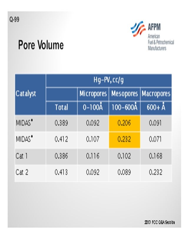
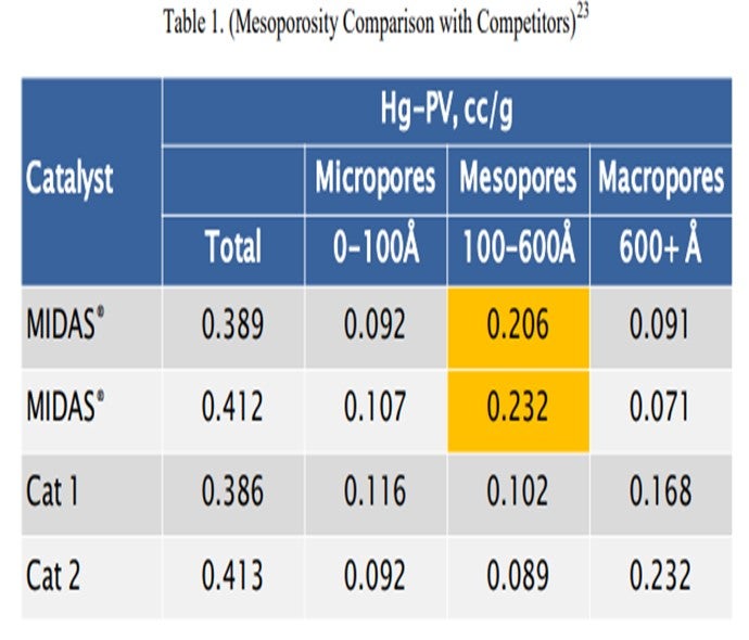
Catalyst design can be optimized to resist the effects of contaminant iron and calcium. High alumina catalysts, especially catalysts with alumina-based binders and matrices such as GRACE’s MIDAS® technology, are best suited to process iron- and calcium-containing feeds because they are more resistant to the formation of low-melting-point phases that destroy the surface pore structure.20 Optimum distribution of mesoporosity also plays a role in maintaining performance because diffusion to active sites remains unhindered, despite high-contaminant metals. Consider that while two catalysts may have similar total pore volume, their mesoporosity can vary greatly.21 MIDAS® catalyst was designed to maximize the abundance of mesopores or pores in the 100 Å to 600 Å size range. Table 1 shows the mercury pore size distribution of MIDAS® catalyst compared to competitive bottoms cracking catalysts.22 As can be seen here, even with similar total pore volume, MIDAS® technology has nearly twice the amount of pore volume in the 100 Å to 600 Å mesopore range compared to the competitive samples. This abundance of mesoporosity enables MIDAS® catalysts to more readily resist the poisoning effect of contaminant Fe and Ca.
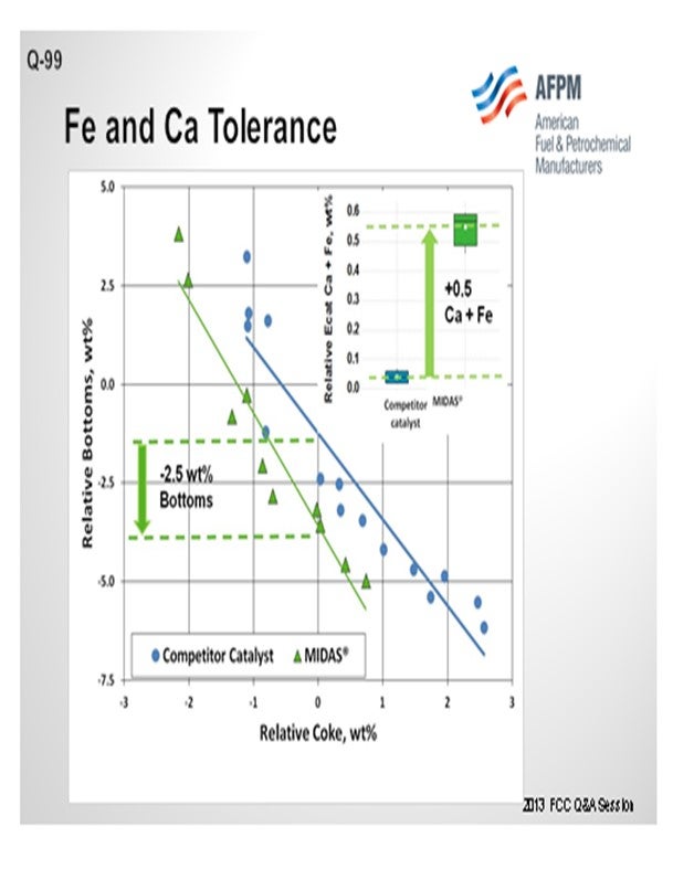
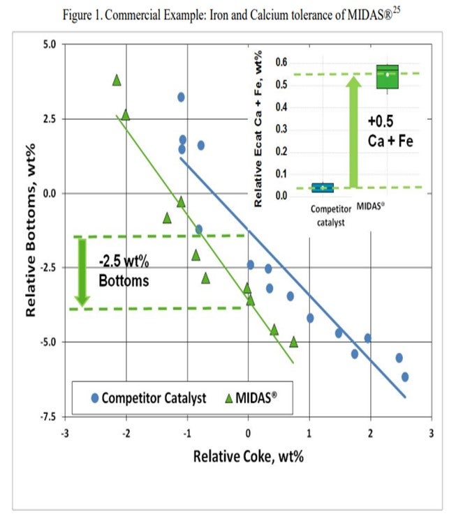
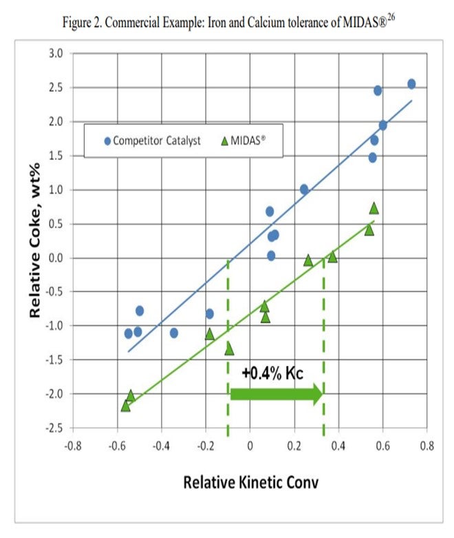
The resistance of MIDAS® to iron and calcium poisoning has been demonstrated in many commercial applications. Figure 1 and Figure 2 present the data from one such example. A refinery was processing a feedstock high in iron and calcium. Over time, the unit exhibited the symptoms of iron poisoning. Iron nodules built up on the catalyst surface and conversion, and bottoms cracking began to suffer. The catalyst was switched from a competitive catalyst to MIDAS®. Upon switching, activity, bottoms cracking, and coke selectivity improved despite the higher metal's levels.
To address the part of the question regarding lab simulation of Fe poisoning, it is not currently possible to simulate the full effect of Fe and Ca poisoning on FCC catalyst performance in laboratory scale deactivation. Iron poisoning causes changes in catalyst morphology and texture in the commercial unit with the formation of nodules on the surface. These nodules have been difficult to replicate in the lab. Laboratory simulation of iron deactivation is an area of ongoing research at Grace.
Impregnation with calcium can cause ion exchange in the zeolite, resulting in undesired changes in the catalyst unit cell size. Grace is working with spray coating techniques to better simulate calcium deposition.
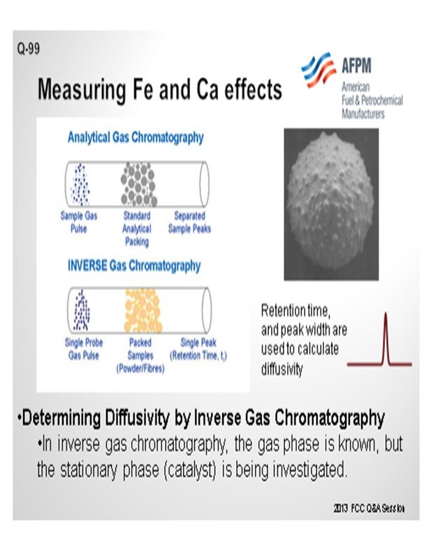
Grace does have an available laboratory test method that can measure the effects of Fe and Ca poisoning. The diffusivity test can confirm adequate diffusion into and out of the pores of a sample of FCC e-cat. The diffusivity test is a proprietary method using inverse gas chromatography, which is depicted in Figure 3. A section of chromatography tube is packed with the e-cat sample. A pulse of a probe gas is shot into the tube, and the rate that the probe molecules pass through is related to the diffusivity. The probe gas molecules will go into the pores of the e-cat, so the rate they pass through will be slower and the diffusivity number will be high. For e-cat with plugged pores due to Fe or Ca contamination, the probe molecules will flow right through, and the diffusivity number will be lower.
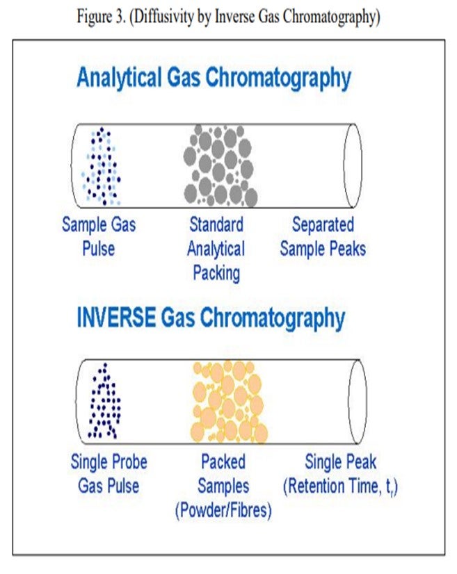
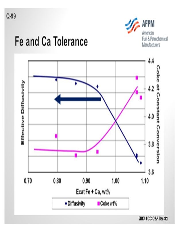
Figure 4 is an example illustrating the impact of equilibrium iron plus calcium on diffusivity. A drop in diffusivity results in an increase in coke at constant conversion. As these contaminants build up on the surface as rings, coke selectivity is lost due to mass transfer limitations, leading to higher rate of secondary reactions, e.g., coke.
'
The ability of a FCC catalyst formulation to tolerate Fe and Ca poisoning will vary greatly depending on the catalyst chemical makeup and the inherent porosity of the fresh catalyst. Grace has experience with units operating successfully with e-cat Fe in the range of 0.5 to over 1 wt%. A good general rule of thumb is that performance can begin to suffer with as little as 0.2 wt% incremental Fe if the catalyst is particularly prone to Fe poisoning.
PAUL FEARNSIDE (Nalco Champion Energy Services)
Increased iron (Fe) and calcium (Ca) removal can sometimes be accomplished across the desalters by carefully acidizing the desalter washwater. The acidizing essentially increases the solubility of both the Fe and Ca into the washwater for the increased removal.
CHRIS CLAESEN (Nalco Champion Energy Services)
If the largest part of the Fe is contained in the solids, the solids removal can be improved with a specific Nalco Champion solids wetting additive. Fe removal of over 90%, with desalted crude Fe levels below 0.5 ppm, has been achieved with this additive.
RAUL ARRIAGA and KEN BRUNO (Albemarle Corporation)
The critical catalyst feature for success with Fe and Ca poisoning is high accessibility, or in other words, a catalyst with superior internal and surface diffusional character. AMBER™ and UPGRADER™ were developed with high accessibility and are proven for tight oils. For additional insight, please see Albemarle’s answer to Question 98.
Regarding contaminant levels, with today’s technologies, an FCC catalyst can operate successfully with iron contents as high as 25,000 ppm and CaO (calcium oxide) as high as 28,000 ppm. Regarding laboratory procedures, Albemarle has developed a deactivation protocol to simulate the impact of high amounts of iron and calcium on a catalyst. The method is called CD-ALFA (Cyclic Deactivation with Accessibility Loss by Fe and Ca Addition) and was developed to simulate the effect of metal contaminants on accessibility. If a catalyst is not evaluated at its actual equilibrated accessibility, then the yields from performance testing are usually misleading. In nearly all cases, traditional deactivation methods, including cyclic deactivation and Mitchell/CPS, result in an Albemarle Accessibility Index (AAI) not reflective of its true value.
Year
2013
Process