Question 67: The industry continues to experience process safety incidents associated with FCC electrostatic precipitators. What are you doing to prevent these incidents?
REYNOLDS (Phillips 66)
Phillips 66 has six ESPs (electrostatic precipitators) in service. We have not been immune to serious incidents on our ESPs. In 1994, we had an ESP explosion, which led to a fatality. So, in order to minimize the likelihood of these kinds of incidents happening again, the company has a standard that all of the refineries are required to follow. It lays out how your safety system is supposed to be configured and which features it is supposed to have. The compliance of the standard is tracked at the corporate level, so all of the refiners have to report if they continue to meet the standard. We have one wet ESP that is downstream of the scrubber, and it must meet the compliance just like regular ESPs.
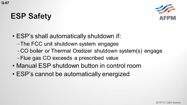
One of the features required by this standard is that the ESP shall shut down if the main FCC safety system engages or trips, regardless of the cause. There are several other features. If the inlet CO (carbon monoxide) level exceeds the prescribed limit in the standard, which says that it can be no greater than 5,000 ppm (parts per million) of CO, the safety system engages. Also, if the air preheater has a safety system on it which then trips, the ESP is required to trip along with it. The ESP must have its own separate shutdown button. The CO is used basically as a surrogate for other combustible material. CO is combustible itself; but if you are having poor combustion in your regenerator, you are likely to be generating CO as well. One of the more important features is that the ESP cannot have the capability to re-energize itself after it trips.
So the highest potential for operating on ESP and explosive composition in your flue gases during startups comes from the use of torch oil along with air preheaters, which can lead to poor combustion. Our recommended practice is to keep the ESP down during startup until the unit is stable. Stability is defined as feed in the unit, stable pressure balance, CO within limit, and nothing bypassed in the safety system. For certain locations, you may not be able to have the luxury of starting up without ESPs. So if you do that, the standard recommends that you have an air preheater safety system as well.
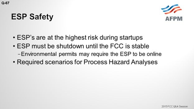
The standard includes some recommendations; for instance, minimizing the personnel around the ESP when you start up or shut down or if there is an upset. It also recommends utilizing the methane analyzer in conjunction with the CO analyzer. And for the sites that do start up with ESP online, having a methane analyzer – in addition to a CO analyzer – is strongly recommended. The standard includes some scenarios you must consider whenever you do a PHA (Process Hazard Analysis), such as the loss of combustion air or any kind of upset in the regenerator, upset in the stripper, low-riser outlet temperature, and pressure reversals. A lot of the information I used for today’s responses came from a presentation by Phillips 66’s own Mike Wardinsky at the 2009 AFPM Q&A Principles & Practices.
LARSEN [Marathon Petroleum Corporation (MPC)]
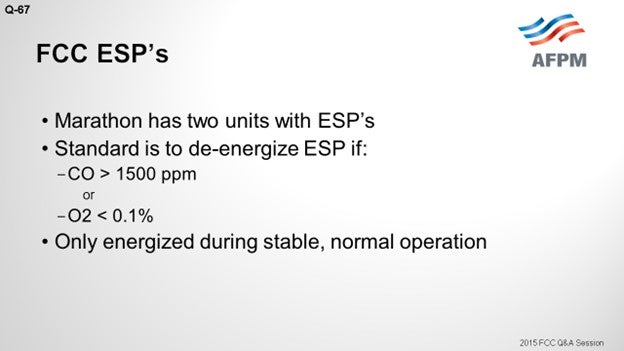
In Marathon, we have two units with ESPs on them. Our setup is very similar to what Mark described with Phillips. Any activation of the normal FCC SIS (Safety Instrumented System) will de-energize the ESP. On the slide, you can see some of the limits that we use. Our trip point for CO is 1500 ppm, which is a little more conservative. Also, we will trip the ESP if excess oxygen is less than 0.1%. So, either of those inputs will act to de-energize the ESP. For safety purposes, we only run our ESPs energized during stable normal operations, not during the times of hot standby or startup, etc.
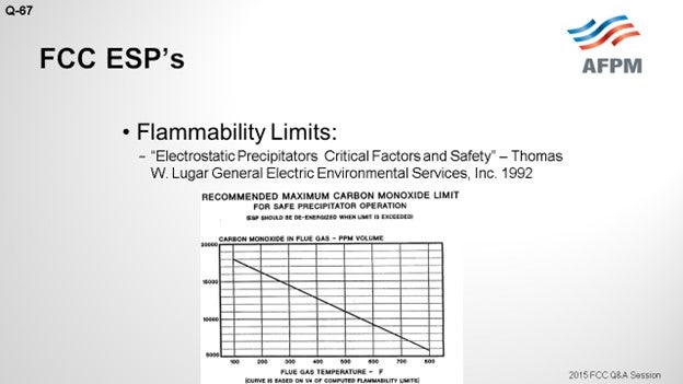
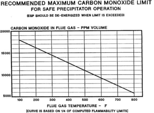
A lot of thought can go into the selection of the right number to use for de-energizing the ESP. An example is the chart on the next slide which includes some numbers, based on the molecules and some inflammability assumptions. This is an example, published by Thomas Lugar at GE1 in 1992, which shows you the magnitude and framework of the danger zone for CO in relation to ESP operation. So, with that, I will put in a plug for our Principles & Practices session tomorrow. I believe it has a topic on ESP safety as well, which will be discussed in more detail tomorrow morning.
KEVIN PROOPS (Koch Industries, Inc.)
Mark and Nik, thank you for your comments. I had the misfortune of visiting the unit Mark mentioned about the week after that catastrophe happened. I want to add a couple of comments to what you described during the startup (when that explosion occurred). Natural gas backed in from the fractionator, through the reactor, and got all the way to the regenerator. I believe that there would not have been any significant CO at that time. Oxygen was high.
So panel members and the audience, if you are worried about ESPs on startup, recognize that they can be very abnormal to what you are used to seeing. I believe the incident investigation also found that the ESP had been in a de-energized state, but it still exploded. So, you have to watch out for potentially explosive mixtures of oxygen and methane at higher temperatures.
ROGER LANOUETTE (Monroe Energy, LLC)
I am curious about the shutdown system. Our analyzer people are telling us that there is interference with CO and methane in doing the analysis and calibration difficulties. Is there a specific analyzer that you have come across that is better for this kind of service? The second part of this question is: Is this an SIL (Safety Integrated level)-rated shutdown system?
UNIDENTIFIED SPEAKER
As far as the analyzer, I cannot speak to what works better in others. I do not think we have a standardized analyzer as far as I know. Do we?
LARSEN [Marathon Petroleum Company (MPC)]
My answers will be published in the final Answer Book. In them, I have detailed the specific analyzer we use. I know a lot of folks are going to the TDL (tunable diode laser) technology, which is a question later on. I think we will talk about response time in Question 76 in a little while, too. I can meet with you after the session to go over the specific analyzer we use with good success.
EMERSON FRY (Delek Refining, Ltd.)
Does anyone have any experience or insight as to whether or not this would be important to have in a partial-burn unit with a CO boiler on the backend? Is that at any greater or lesser risk than a full-burn unit?
J.W. BILL WILSON (BP Products North America Inc.)
Just to add another question about it, is there greater risk with an ESP and CO boiler or is the risk the same? It is at least the same. Okay. We actually managed to blow up an ESP that had a CO boiler on it, so the risk is there. So yes, I certainly think the standards will be the same on our units. I imagine other people who have standards will probably apply the same standards.
RIK MILLER (Phillips 66)
I will address two issues. One is the analyzer. As Nik said, the Phillips 66’s standard also calls for TDL analyzers because they are very fast-responding and very accurate and sensitive for CO. You can also get a TDL for methane. Some of our units have that as well.
As Kevin pointed out, the incident that Mark mentioned would not have been stopped by one of these analyzers. The explosive mixture was fuel gas, and the ESP was not energized at the time. What that site and about half of our other FCCs have done since then is install these overhead blinding devices between the reactor overhead and the main fractionator. Those are reusable devices that can seal off the reactor from the main fractionator so you avoid getting migration of fuel gas or other hydrocarbons during periods when you are down or starting up. Those are very effective, and we recommend them strongly in our system.
ROBERT (BOB) LUDOLPH [Shell Global Solutions (US), Inc.]
I would like to expand Question 67 to include the representatives of the electrostatic precipitator manufacturers who may be in the audience. What are the electrostatic precipitator manufacturers doing to help improve the safety and operation of their equipment, and, in turn, the overall safety of the refining facilities?
NEIL DAHLBERG (Hamon Research-Cottrell, Inc.)
Hamon Research Cottrell has supplied a large number of precipitators to refineries in the United States over the past 15 years. Many of these suggestions are implemented in our design, and we participate in a HAZOP (Hazard and Operability) study at the beginning of each design process. An additional level of protection would be to limit the power to the operating transformer rectifies at startup to stay below the threshold of sparking, which will eliminate a source of sparking in the precipitator and a potential source of ignition of combustible gases.
NIKOLAS LARSEN [Marathon Petroleum Company (MPC)]
The function of an ESP is to remove particles from gaseous streams by passing the gas between a pair of electrodes: a discharge electrode at high potential and an electrically grounded collecting electrode. Sparking in an ESP is an ignition source for a fire or explosion if enough combustibles and oxygen are available.
Specific to FCC units, the biggest concern is carbon monoxide (CO). CO is very unstable; and as such, it is difficult to measure and deliver the information fast enough in order for a manual process adjustment.
Marathon Petroleum Company (MPC) utilizes an extractive system in one FCC unit, and the analyzer is the ABB AO2000 platform with a Magnos 106/206 Paramagnetic Oxygen Analyzer and Uras 14/26 Non-Dispersive Infrared CO Analyzer. Our analyzer is mounted on the deck at the duct; so our sample line is very short, probably in the 10- to 20-foot range. Overall, we have been pleased with this setup.
Others in industry have had success with tunable diode laser analyzers (see Question 76). MPC automatically de-energizes an ESP at a conservative level of either excess O2 (<0.1%) or CO (>1500 ppm). Other actions that de-energize the ESP include activation of the SIS Feed Divert Sequence, control room ESD (emergency shutdown) button, and two field ESD buttons. There is no automatic re-energizing. MPC also does not energize an ESP during times of unstable FCC operation, such as startup or hot standby, when torch oil is being utilized.
The following additional resources are available for your review.
-
“Reducing the Risk of Fires and Explosions in FCC Electrostatic Precipitators”, Michael Wardinsky’s presentation at the 2009 AFPM Q&A Principles & Practices.
-
“Advances in Fluid Catalytic Cracking – Testing, Characterization, and Environmental Regulations”, edited by Mario L. Occelli; Chapter 18 (18.4.8) on ESP Safety by Jeffrey Sexton.
-
“Electrostatic Precipitators Critical Factors and Safety,” a paper by T. Lugar which also calculates safe limits for CO when operating an ESP (GE Environmental Systems, 1992).
ALAN STAHL (CSI Engineering)
CSI Engineering evaluates the safety procedures and systems of our client refineries’ electrostatic precipitators (ESPs). Of particular importance is the precipitator emergency shutdown system that eliminates high voltage sparking as a source of ignition in the event of hazardous process conditions. Shutdown system designs vary in details of wiring, control inputs, and procedures for use. Some systems and practices prove to be inadequate. We apply our experience to advise our clients of what we consider the most effective features and procedures.
CHRIS STEVES (Norton Engineering)
Some of our clients have installed automatic shutdown systems for ESPs, which may be triggered by any of the following initiating factors:
-
High ESP inlet CO or methane concentration [as measured by tunable diode laser (TDL)],
-
FCC unit trip, or
-
CO boiler trip.
Some refiners will also keep the ESP de-energized during unstable phases of the startup, such as when first introducing torch oil to the regenerator. A thorough analysis of the unit configuration and potential causes of an ESP incident should be reviewed by a multifunctional team in the refinery so that the best solution can be implemented. Consultation with outside experts familiar with FCCU ESPs and previous industry incidents is normally useful.
Year
2015
Process
Question 62: What are causes of foaming in crude pre-flash drums and towers, and what options are available to mitigate foaming?
SHELTON (KBC Advanced Technologies, Inc.)
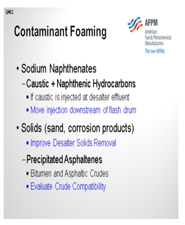
Surfactants cause foaming. Mike will discuss surfactants and amines that should not be in the crude. Sodium naphthenate is a common surfactant produced by the reaction of caustic injected at the desalter effluent and naphthenic hydrocarbons.
A simple solution is to move the injection downstream of the pre-flash or pre-fractionator to the bottom pumps. If the injection point is at the desalter effluent, solids and corrosion products can cause foaming.
Improving desalter solids removal will mitigate foaming. Precipitated asphaltenes that frequently occur with bitumens and asphaltic crudes can also cause foaming, so we would evaluate crude compatibility in that case.
The question includes pre-flash drums and towers, which I assume is a pre-fractionator. These applications are quite different in design and operation. In our pre-fractionator designs, we consider C factors, internals, tray design, and tower loadings.
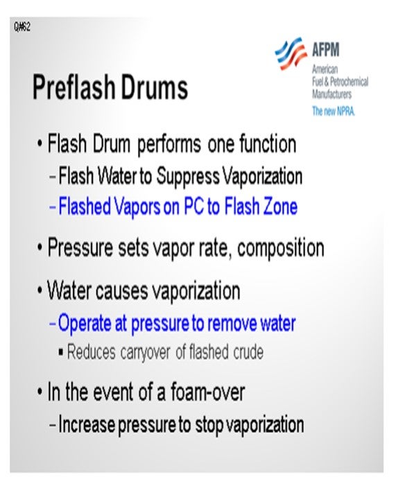
We have used pre-flash drums in our latest grassroots designs because the hot trains have been so efficient that crude heater inlet temperatures are 600ºF to 610ºF. A flash drum removes water and requires lower pressure to suppress vaporization at the end of the hot train. The flash drum design avoids elevated pressures in the hot train and 900-pound flanges. Obviously, we specify vertical versus horizontal. We consider height versus diameter and liquid superficial velocity versus vapor velocity to optimize the ratio. We also consider disengaging height and the feed distributor inlet design. Of course, temperature and pressure have a major impact.

The pre-flash drum performs two functions: flashing water and suppressing vaporization. Many pre-flash drums are operated to remove light hydrocarbons. However, water causes vaporization, and operating pressure and temperature determine the vapor rate and composition. It is important to model the optimum pressure. Operate at the pressure required to remove water and not generate excessive hydrocarbon vapor load, which can result in carryover of bottoms.
In our designs, flashed vapors are sent to the flash zone. Designs where the flashed vapors are introduced in higher sections of the column can create problems. For any design, in the event of a foamover, temporarily increase pressure. With the flash drum, increase pressure until there is no vaporization. That will stop the foamover. It is important to have a pressure controller on that vapor line to the flash drum.
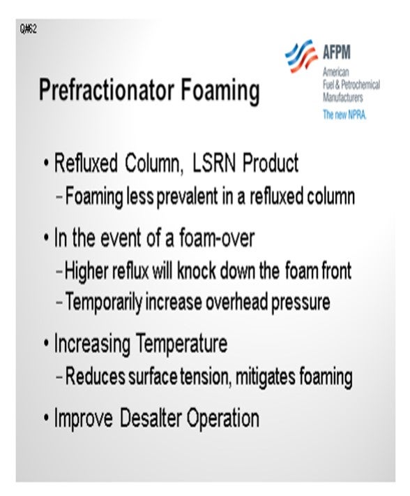
Pre-fractionator foaming is less likely because it is a refluxed column with an overhead product. The trays mitigate foaming, and the liquid loading should tend to knock down the foam. Again, in the event of a foamover, you could temporarily increase pressure. This may not be obvious, but we try to design for higher temperatures to reduce surface tension, which also mitigates foaming. In a new design, the pre-flash drum operating temperature is determined by the location in the hot train. Finally, improving desalter operation will mitigate foaming in the downstream columns.
BASHAM (Marathon Petroleum Corporation)
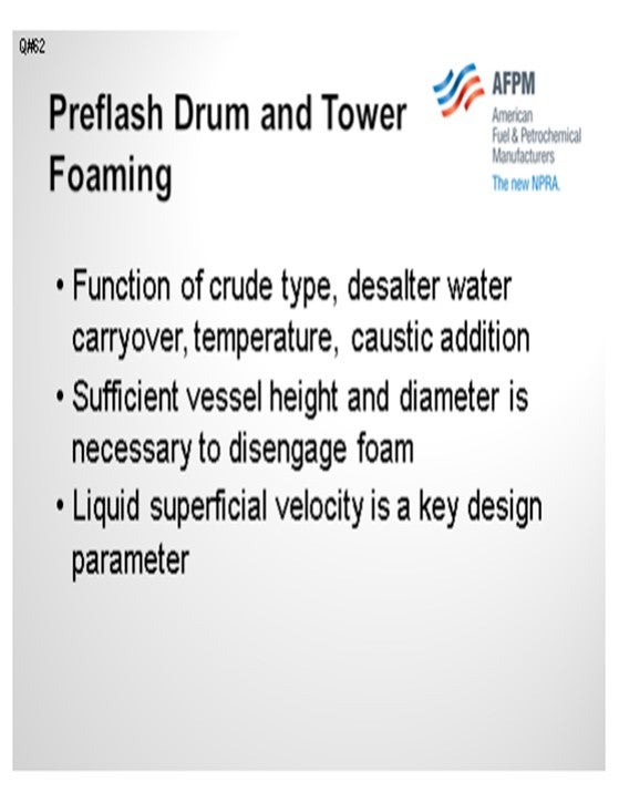
I want to reinforce some of Al’s points here. As he already mentioned, pre-flash tower or vessel foaming is a function of crude type salt or water carryover, temperature, and caustic addition. You are always going to have foaming occurring in a pre-flash drum or tower. The key here is to manage the foam and keep it in the tower. You must have sufficient vessel height and diameter necessary to disengage the foam. As Al also mentioned, the liquid superficial velocity is the key design parameter. It is important to keep in mind that the smaller the diameter of the vessel, the larger the foam height; so in narrow vessels, the liquid superficial velocity will need to be low in order to keep the foam height low. It is possible to add silicone-based antifoam to the pre-flash drum or tower, but consideration needs to be given to the downstream, gasoline, and distillate hydrotreater reactor catalyst.
DION (GE Water & Process Technologies)
Al and Kevin covered operational and mechanical issues regarding foam. Part of the question asked about the causes of foaming. There are surfactants in crude oil. Surfactants can be any organic molecule that has an atom that is not carbon or hydrogen, such as organic acids, organic amines, mercaptans, and other molecules with a polar group associated with them.

RUSSELL STRONG (Champion Technologies)
I have heard several comments that silicone antifoams in crude are problematic. There have been recent events offshore in the Gulf where so much antifoam was being used upstream that it was actually poisoning hydrotreater catalyst in the refinery from the upstream application. Other causes of silicone contamination can come from the crude while trying to control foaming in a flash drum or in a crude tower. To control those, silicone antifoams are sometimes used with occasional success. Several years ago, at a refinery down in the Houston, Texas area, I encountered severe foaming in a crude tower that would not go away. Standard silicone antifoams did nothing to solve the problem, but a fluorosilicone antifoam worked well. It was far more efficient and actually worked where the polysiloxane was deficient. It also offered less risk of downstream silicon contamination. So, keep this in mind as an option if you have crude unit foaming.
STEVEN FISCHER (Delek Refining)
At a previous refinery, we reintroduced the vapors to the flash zone with the result being quench to the flash drum that resulted in poor cutpoints. When we introduced the flash vapors from the flash drum to the flash zone, we saw that that the flash drum had actually acted like a quench, which could result in a poor cutpoint at the bottom of the crude tower.
SHELTON (KBC Advanced Technologies, Inc.)
Simulations do not indicate flash zone quenching if, as previously mentioned, the flash drum operating pressure is optimized to flash-only water. We have evaluated the flow schemes in models with the two streams mixed outside of the column and combined in the flash zone, but we get the same overflash.
STEVEN FISCHER (Delek Refining)
That was our assumption when we designed it that way, but our performance did not show that result. Our performance improved when we introduced it higher up.
ANDREW SLOLEY (CH2MHILL)
Addressing that last comment, I think what you are seeing there, when you see the poor performance, is the mixing of transfer line liquid with the vapor coming in, which is an issue with the equipment and not having the vapor segregated from the transfer line.
SHELTON (KBC Advanced Technologies, Inc.)
Our designs do have a separate flash drum vapor nozzle in the flash zone. It is important to have a pressure controller on the flashed vapor line, so the drum is not riding on the lower flash zone pressure. I do not know if that is your case or not. Do you have pressure control on the pre-flash drum? If not, a large pressure drop will produce a very high vapor rate, and then hydrocarbons will be flashed. In that case, there could be some quenching. We try to just flash the water and no hydrocarbons. When you think about it, if there were substantial light hydrocarbons, the desalter would overpressure. So, there are not a lot of light hydrocarbons in the crude because the only difference in the flash drum versus desalter operation is the desalter pressure, which is also low compared to the elevated hot train pressure.
STEVEN FISCHER (Delek Refining) We had some light hydrocarbons going overhead in addition to water.
SHELTON (KBC Advanced Technologies, Inc.)
There may also be recycle streams quenching the flash zone.
ROBERTSON (AFPM) Al, could you comment on the superficial velocity?
SHELTON (KBC Advanced Technologies, Inc.)
Liquid superficial velocity is a function of the vessel height versus diameter and design of the drum, which differs for vertical versus horizontal vessels. It is specific to each design and not a variable for an existing drum. Pressure is the important operating variable. If there is no pressure controller on the vapor from the flash drum, then that deficiency can be remedied online because there is usually a block valve at the column. In that case, the back pressure controller can be installed online.
VILAS LONAKADI (Foster Wheeler USA Corporation)
Is there any experience with the use of any internals in the pre-flash drums?
SHELTON (KBC Advanced Technologies, Inc.)
There are several types of feed distributors, including vortex tube clusters (VTC) and tangential nozzles. There are many effective feed distributors that will improve disengaging.
VILAS LONAKADI (Foster Wheeler USA Corporation)
Not about just the feed entry, but in the drum itself.
SHELTON (KBC Advanced Technologies, Inc.)
We do not recommend demisters on vapor outlets, and flash drums do not typically have any internals.
VILAS LONAKADI (Foster Wheeler USA Corporation)
Some vendors offer vortex tube clusters. I want to know if anyone has used them.
SHELTON (KBC Advanced Technologies, Inc.)
Yes, we mentioned vortex tube clusters (VTC), which have been used successfully in drums that operate at high velocities. We have also seen VTC distributors used for revamps to increase throughput at higher drum velocities. They have been very effective.
VILAS LONAKADI (Foster Wheeler USA Corporation)
Did it reduce foaming?
SHELTON (KBC Advanced Technologies, Inc.) Yes, VTC distributors have been used to solve foaming problems for existing vessels.
SHELTON (KBC Advanced Technologies, Inc.)
Foaming in flash drums and pre-fractionators is often caused by crude contaminants. Inorganic fines (sand, corrosion products, etc.), precipitated asphaltenes and sodium naphthenates formed from the reaction of caustic and naphthenic hydrocarbons have been identified as precursors. If caustic is injected at the desalter effluent, a simple solution is to move the caustic injection downstream of the flash drum to the pre-flash bottoms or hot train pumps.
The immediate solution to a foaming problem is to increase pressure to decrease vaporization. In a prefractionator, in addition to increasing pressure, higher reflux or wash rates will tend to knock down the foam front. Increasing temperature will reduce surface tension and mitigate foaming. Long term solutions include improving desalter operation (particularly solids removal) and improved selection of treating chemicals for the preheat train and desalters.
The design and operation of pre-flash drums and refluxed pre-fractionator columns are different. Vessel design (vertical versus horizontal) and disengaging height affect foaming. KBC design guidelines for pre-flash drums include height versus diameter, liquid superficial velocity versus vapor velocity, disengaging parameters, feed distributors and pressure. For any design, increasing operating pressure will reduce foaming.
Pre-flash drums are located in the hot crude train downstream of the desalters to flash water and suppress vaporization at the end of the hot train. Flash drum vapors on pressure control are routed to the crude column flash zone. Flash drum pressure sets the vapor rate and composition. Simulations show that water causes vaporization in heat exchanger services at the end of the hot train, not light hydrocarbons. Very light hydrocarbons would overpressure the desalters, if present. Simulations will determine the flash drum pressure required to remove dissolved water from the desalter effluent. The flash drum should be operated at the pressure required to remove water and no lower to reduce carryover of flashed crude. In the event of a foamover, the foam can be broken by temporarily increasing drum pressure to reduce vaporization. Good desalter operation with no water carryover to the flash drum will minimize foaming. Desalters should be operated with less than 0.5% BS&W in the effluent. Prefractionators are typically refluxed distillation columns with an overhead product such as light naphtha and may also have sidecuts. Foaming is less prevalent in a refluxed column. In the event of a foamover the foam front can be broken by first increasing reflux rate and if necessary, temporarily increasing overhead pressure.
BASHAM (Marathon Petroleum Corporation)
Foaming is always present in pre-flash drums and towers. It can be a function of several parameters including crude type, desalter performance (water carryover), drum or tower temperature, and caustic addition. Depending on its feed location in the atmospheric crude tower, pre-flash drum vapor can cause black distillate, black atmospheric gas oil, and increased atmospheric tower bottoms if the foam contains flashed crude. Similarly, in pre-flash towers foam with entrained flashed crude can cause black naphtha. The key to managing foam is keeping it in the pre-flash drum or tower.
A properly designed vessel (drum or tower) will allow sufficient height to disengage the vapor from the liquid. The most important design parameter is the superficial velocity of the flashed crude. The foam height is directly proportional to the liquid superficial velocity. The liquid superficial velocity must be sufficiently low enough to keep the foam height below the vapor outlet of the drum or tower. The foam height is also a function of the tower or drum diameter (cross-sectional area.): the smaller the diameter, the larger the foam height. This means that foaming will be a bigger concern in narrow vessels, so the liquid superficial velocity will need to be low in order to keep the foam height low.
It is possible to add silicone-based antifoam to the pre-flash drum or tower, but consideration must be given to downstream gasoline and distillate hydrotreater catalyst silicon loading.
LEE (BP Products North America)
A potential cause is water carryover out of the desalter that is vaporized in the flash drum. If there is water carryover and high shear stresses associated with a letdown valve with high pressure drop, this situation can generate small droplets which would contribute to foam generation. Foaming is often associated with high vapor rates, so a crude with a significant amount of vaporization at the flash drum conditions may have high potential for foaming. Antifoam use, and additional enhanced separations hardware, such as vortex cluster internals, can be considered.
DION (GE Water & Process Technologies)
Any organic molecules with atoms other than hydrogen or carbon are potential surfactants. Examples of such molecules are; alkyl phenols, organic amines, organic acids, and mercaptans. Foaming can be mitigated through the use of a defoamer or antifoam chemistry.Defoamers function by reducing the interfacial surface tension and viscosity. Antifoams function by modifying the interfacial surface elasticity. Most products commercially available from specialty chemical suppliers, such as GE Water & Process Technologies, function in both manners due to the behavior of their surfactant structure. The most effective defoamers in hydrocarbon environments are typically silicone based. If silicone poisoning is a concern, non-silicone-based defoamers, such as glycolic materials, are available.
BRUCE WRIGHT (Baker Hughes) Pre-flash tower foaming is most often caused by high solids loading coupled with high gas flows. Foam control with Baker Hughes Si-based antifoams has proven to be effective.
DENNIS HAYNES (Nalco Energy Services)
Crude viscosity, hydrocarbon polarity, solids content, caustic use, and vapor disengaging in flash sections and tower bottoms are discussed as causes for foaming. Antifoams have been around for quite a while that may be utilized in this area; however, the first step in corrective action is to determine that it is actually a stabilized foam layer and not tower flooding. There are instances where pre-flash towers are operated above design or have had some internal damage that causes flooding which is mistaken for foaming.
ANDREW SLOLEY (CH2M HILL)
One major cause of foam formation in these units is surface-active agents stabilizing the foam film on the liquid-vapor interface. Some of these agents are inherent components of specific crudes. However, many of them have been added to crude as well stimulation, drag-reducing, anticorrosion, or hydrogen sulfide scavenging additives. With continued production of heavier crudes and more aggressive well stimulation operations, foaming problems should be expected to get worse.
Solutions to foam formation include; antifoaming additives; foam-breaking inertial separators; and modifying operating conditions.
Silicone-based antifoaming additives can be effectively used. Their downside is that they vaporize and end up in the lighter products, particularly naphtha. This puts the antifoam into the downstream naphtha hydrotreater feed. Few hydrotreaters can tolerate this. Antifoams are rarely used.
Foam-breaking inertial separators have been used in a number of plants. They are derived from equipment design for oil production operations. In the oil fields they are proven technology. Experience in refineries, while limited, has been mostly successful. For certain plants and feeds they may be a choice worth serious consideration.
The most common method of avoiding foam-created problems has been to modify the plant operating conditions. This may include changes in feed rate, pressure, or temperature. Feed rate reduction increases effective residence time in equipment. It also reduces total vapor rate formation. While expensive, some plants are constrained to do this. Increasing pressure reduces vapor formation and increases vapor density. Both reduce the volume of vapor. Increasing operating pressure reduces foam problems. Temperature changes are more complex. Higher temperatures (at the same pressure) create more vapor volume, they also decrease liquid viscosity. These are competing changes. More vapor volume increases foam make. Lower viscosity speeds foam decay. In a plant with a foam problem, small temperature changes, in either direction, may help solve the problem. Experience has shown an operating temperature change as little as 10°F may change the vapor volume, or the viscosity, enough allow the flash drum or tower work, or be catastrophically worse.
Proper pre-flash installation includes balancing many factors including equipment size, expected operating conditions, and how to connect the pre-flash system to the existing unit. Revamps to add, or improve, pre-flash drums or towers need to be carefully evaluated.
Year
2012
Process