


Question 10: What causes metal-catalyzed coking (MCC) that obstructs catalyst circulation in CCR reformers? What actions do you take to mitigate MCC formation?
BILL KOSTKA (AXENS NORTH AMERICA)
Metal-catalyzed coke (MCC) formation typically occurs on 3d valence transition metals such as iron and nickel. Under CCR-like conditions of low hydrogen partial pressure (less than about 620 kpa), high temperature (more than about 480 °C) and low or stagnant flow, hydrocarbons can adsorb and completely dissociate on these metals. The resulting adsorbed, dissociated carbon can then dissolve into and change the metal structure. Once a nanosized portion of the metal becomes supersaturated with carbon, carbon begins to precipitate in a tubular crystalline form breaking the carburized-metal fragment away from the parent metal with the carbon nanotube continuing to grow between them. Despite their fragile appearance, these carbon nanotubes are incredibly strong and can readily damage equipment when present in sufficient numbers.
Mitigation of filamentous carbon growth is best achieved by reducing the possibility of hydrocarbon adsorption on the problematic iron surface. Two methods have been used to successfully achieve this goal in CCR reformers: 1) passivation of the metal surface with an adsorbate such as sulfur and 2) use of a more appropriate metallurgy.
Research done by HJ Grabke et al. has shown that very little sulfur, about 0.5 wppm in the naphtha feed, is required to adequately passivate the metallurgy of a CCR reformer. As a result, most CCR reformers are operated with roughly 0.5 wppm sulfur in the feed. Some refiners may rely on incomplete naphtha pretreatment to supply this sulfur, however, addition of a known amount of a sulfur-containing species to the feed ensures adequate passivation on a continuous basis.
Carbon steel is very vulnerable to MCC formation. Alloying carbon steel with increasing amounts of chromium and molybdenum reduces this vulnerability. These two metals tend to migrate to the steel’s surface and greatly dilute iron’s presence there. As a result, there are much fewer Fe-Fe neighbors necessary for hydrocarbon adsorption, dissociation and dissolution into the steel structure. A 9Cr-1Mo alloy steel greatly reduces MCC even at 650 °C. Utilization of this alloy with on-oil sulfur injection virtually eliminates MCC even at 650 °C.
DAVINDER MITTAL (HPCL Mittal Energy)
The catalyst circulation in CCR may be obstructed due to other reasons as well besides metal-catalyzed coking (MCC). However, the metal catalyzed coking presents a serious problem especially in low pressure CCR reforming units.
The processes of metal catalyzed coke formation will cause particles of the heater tube metal to break away from the tube surface. There is also an increased risk immediately following replacement of heater tubes. The coke formed in the furnace tubes may eventually migrate to the reactors and lodge behind the scallops or baskets. These coke deposits can grow until the scallops or baskets are deformed, affecting catalyst circulation, unit performance or even leading to an unplanned shutdown.
The recommended approach is to generally operate the Naphtha Hydro-treating (NHT) unit to remove essentially all of the sulfur in the feed. This will ensure that other contaminants (nitrogen, metals, oxygenates, etc.) are also removed from the feed to the extent achievable by the NHT. Organic sulfur is then added to the CCR reformer unit feed with a chemical injection system pumping in a specific and controlled amount of organic sulfur compound to achieve the target recommended by the licensor. This provides the refiner with independent control of the sulfur in the feed to the unit that can be changed as needed if feed rate or operating conditions change.
Our Continuous Catalytic Regeneration Reformer Unit was commissioned in May’2012. However, within one year of operation, the unit started experiencing several performance issues including restriction of catalyst flow in some of the spider legs of all 04 reactors , higher pressure drop and lower endotherm in reactors (more severe in 2nd Reactor, 60-70% of design value) and lower RON than design.
In view of the above issues, it was decided to shut down CCR during March-April’2014 and inspect reactors. Significant unexpected damage of reactor internals was found.
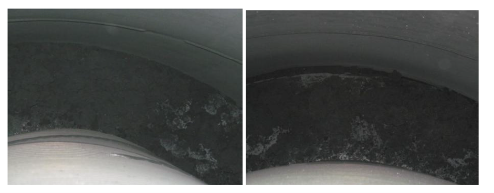
Picture-1: Huge quantity of coke in annular space between reactor grid and shell
Picture-2(a): Last panel of outside reactor grid found fully bulged with huge coke build up
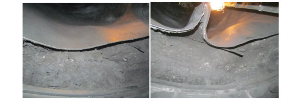
Picture-2(b): Last panel of outside reactor grid found fully bulged with huge coke build up
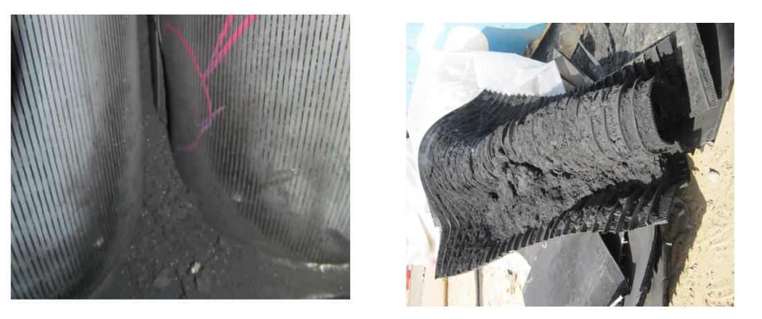
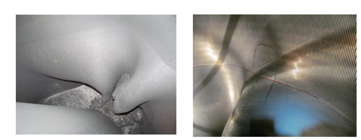
Picture-3(a): Shiny coke between and inside scallops leading to bulging and fish mouth cracks

Picture-3(b): Shiny coke between and inside scallops leading to bulging and fish mouth cracks
A joint root cause analysis with Licensor confirmed presence of Fe and carbon graphite (high carbon content) in the coke samples. During cleaning of the scallops, presence of lot of hard shining coke (metallic coke) was observed along with soft coke. It was concluded that coke build up in reactors/scallops/grids may have taken place due to metal catalyzed coking considering problem with DMDS dosing pump during initial year of commissioning as well as due to other reliability issues like frequent trip of recycle gas compressor. The presence of metallic coke in reactors may have acted as nuclei and further catalyzed the coke growth during recycle gas failure.
The heater tube thickness measurements also indicated some loss of thickness indicating metal catalyzed coking in addition to other forms of coke. The level of thickness loss was fortunately not alarming to inhibit future operation.
Based on root cause analysis certain recommendations were made to minimize metallic coking and damage to reactor internals.
Metallic Coke:
Maintain sulfur level 0.3 to 0.5 ppmw on CCR feed to be substantiated by presence of detectable amount of H2S in recycles gas and 100-150 ppmw of ‘S’ on catalyst sample.
Operate Naphtha Hydro-treating (NHT) unit to remove essentially all of the sulfur and other contaminants in the feed. Inject DMDS in CCR feed through dedicated facility to maintain recommended range of sulfur.
No flame sweeping/scattering on the furnace coils.
Maximum Tube Metal Temperature (TMT) to be restricted below 620oC.
Operation of heater burners within the design regime (maximum allowable process absorbed duty per burner: 1.0 Gcal/h).
Perform positive material identification of tube metal to confirm P9 (confirmed).
Other Coke/ catalyst agglomeration due to coke:
Improvement in reliability of recycle gas compressor.
Check for cold spider legs and try to restore catalyst circulation
Check for quality and temperature of net gas from CCR to avoid condensation in reactor spider legs
Maintain recommended coke ( 4 -5 wt%) on spent catalyst
Stress build up in Reactor internals:
Carry out emergency catalyst circulation in case of unplanned trip of the Recycle Gas compressor to relieve the mechanical stress built up due to difference in the thermal expansion coefficient between catalyst and reactors internals.
Year
2019
Submitter
Process
Question 61: Have you found that you needed to install a methanator upstream of a chlorided catalyst isomerization unit to remove carbon monoxide (CO) from the feed? What is the source of the CO and how much of a difference has the addition of the methanator made to catalyst life? What is the expected payout for the cost of the methanator?
FERNANDEZ (Jacobs Consultancy Group)
This question is quite related to the previous one: the same type of system—the platinum on aluminum-based catalyst. The problem now comes from the oxygen ingress coming in with makeup hydrogen, with the culprit typically being CO and CO2. The problem is slightly different here. The amount of oxygen that you bring is not as high, obviously, because of lower mass flow of hydrogen in comparison to the feed; but it’s much more pernicious. It’s typically a problem when you have nothing and there’s not much you can do in the isomerization unit. So what you really have to look at here is the alternatives to solving the problem. Obviously, methanation is an alternative; but, as always, we would always recommend looking at where the problem is and seeing if you can address it there, rather than spending capital on additional equipment.
It’s important that we look at what may be the sources of CO and CO2 in the refinery hydrogen systems. Everyone traditionally thinks that CO and CO2 are formed in the steam reformer; that is true. Older type hydrogen plants have solvent extractions and a methanation unit to eliminate CO and CO2 in the hydrogen. So there you will see, at most, 10ppm CO plus CO2.
Instead of having this methanation system, modern hydrogen plants have PSA units that are pretty good at removing both CO and CO2; but there’s always a balance between the purity that you get in the PSA unit versus the recovery. So in some PSA units where the units are being pushed either in terms of capacity or on hydrogen recovery, you do have the potential of having CO leakage coming out into your hydrogen system.
A third source—and it’s sometimes forgotten about—is that there is CO coming out with the net gas from reforming units. Some of it might be residue from regeneration operations, but some of the CO actually comes by formation of CO in the unit, particularly in what we would call wet units or units that have a high moisture content in the recycle gas. In those units, CO is formed on a reverse water shift reaction. So this is an area that you have to look at because there will be a source of CO that you may be able to manage.
And lastly, we see there are many refiners today that try to recover hydrogen to the max from all their other services, including FCC units, Coker off gas, and off gas from the hydrotreaters. Those streams tend to be contaminated with all kinds of contaminants, including CO and CO2.
Regarding the solutions to the problem, unfortunately it’s not a very easy problem to track down. The reason is that many refineries have several sources of hydrogen coming together and mixing in a big hydrogen header system. Trying to find out where the CO is coming from is pretty difficult.
I recall that years ago, we were helping a customer that had a Penex unit in which they were having a very high rate of deactivation of the catalyst. This refinery definitely had what we would call a wet reformer. They were injecting large amounts of water and chlorides to try to keep catalyst activity. You definitely knew, and could measure, the amount of CO that was coming in that hydrogen stream.
Unfortunately, that was not the only hydrogen stream. When we tried to correlate the rate of the activation of the catalyst with the amount of CO that was in the hydrogen, the rate of deactivation was higher. One idea was to put in a methanation unit, but you’re only going to resolve part of the problem. And really, the problem is in the bad operation of the reformer. So methanation didn’t seem to be a very good solution there.
We’ve also talked with other refiners that actually had a major problem with CO and CO2, but these guys are talking in the range of 100 to 1000 ppm contaminants of the makeup hydrogen. They know very well what the source is. This refinery recovers hydrogen from FCC, cokers, and hydrotreaters, and they do that through a cryogenic unit. So for them, there really is no alternative. They had to put in a methanation unit and they’re very happy with it. Once they put in that methanation unit, their operation became very stable. They completely eliminated the catalyst deactivation that was being caused by their makeup gas.
In summary: If you cannot prevent or remove it, you’re going to have to methanate it. Methanation is the ultimate solution. It works. There are simple systems. It’s well known how they operate. It’s a relatively low capital cost solution, probably three-quarters to a million-dollar installation for a small hydrogen stream. We would recommend that before anyone commits to the methanation unit, they do two things: One, make sure you know the sources of the CO and confirm that you cannot solve them at the source, which is obviously always the cheapest solution. Secondly, make sure that it is the only problem with contamination in your isomerization unit, because you may be calculating a payback on that methanation unit based on large catalyst deactivation which might not be all caused by the CO.
HAZLE (NPRA)
Jay.
ROSS (Axens)
Yes, thank you, Pedro. We agree with all those points, but I would also like to take a minor issue with the CO contention. We naturally limit all oxygen. That is going to the Isom process because of the potential for H2O formation. This occurs with alcohol as a direct formation of water and with the CO, CO2 in the possibility of methanation. That’s typically limited to about 10 ppm in the hydrogen gas. However, these units do operate at very low temperatures and the conditions in the Isom—in our view—significantly promote methanation. A reversible poison by carbonyl formation with the platinum is probably a more significant concern, and thereby affects the metal activity of aromatic saturation preventing coking, etc. We’ll go to the next slide.
In one particular unit, it was a little different than the unit that Pedro showed. This is a two-reactor traditional chlorinated aluminum Isom unit, but with the lead benzene reactor, because there was a relatively high benzene in the unit. Here, they had a problem on a methanator on the hydrogen plant, so a fairly large concentration of CO passed through the Isom unit as a wave. The benzene reactor experienced a sharp increase in delta P and the exotherm from the saturation of the benzene was temporarily inhibited almost completely as the CO passed through.
And then there were some thermal effects causing the lag to be a little different, as you might expect; but effectively, the benzene was pushed downstream and had to be picked up, in this case, by the lag reactor. Over the course of about four hours, everything came back to normal. That’s not necessarily proof positive that there was no catalyst damage; but in our view, there was limited permanent catalyst damage due to methanation and water formation, and, rather principally in this case with CO, a temporary poison of the platinum metal effects.
HAZLE (NPRA)
Clever.
HATZEL (Tesoro)
Just a quick history of the Mandan methanator: We had a C5/C6 Isom unit installed in early 1981. After multiple catalyst poisoning episodes and catalysts regeneration or replacement, the methanator was installed in 1985 and did seem to work. Looking back to the files, we see that a CO-related poisoning pretty much ceased. That doesn’t mean that we didn’t find other ways to kill the catalyst in the years after that. We did, with alcohols and other things that got into the feed. As late as 1995, they partially bypassed the methanator inadvertently. They went out and found the bypass valve cracked open, but it was too late. Within just a few days, the catalysts had been poisoned. So that has kind of been our experience.
When talking to our Isom experts, I think we give pretty serious consideration, especially with the advent of some of the benzene regulations, to having methanators on future Isom units.
HAZLE (NPRA)
Those are the panel responses. The last question is on isomerization. There is one right here. Questions? Comments? I think I saw a hand over here.
OYEKAN (Marathon Petroleum)
Soni Oyekan, Marathon. I just have questions for the panel. In the case of the example for Mandan: Was the hydrogen recycled or once-through to Isom unit initially? Secondly, for Jay: In terms of the levels of concentration of CO and CO2 that you’ve suggested, I believe the upper limit is 10. We might have temporary relief after the carbonyl is formed initially. Should we worry if it’s above that or basically be satisfied that we’ll have this passivation of this carbonyl? So, there are two questions. One is about the effect of this carbonyl with hydrogen once-through units, and the second one will be max carbonyl and CO and CO2 level that we’ll be looking at in these streams.
HAZLE (NPRA)
Let’s start with Jay.
ROSS (Axens)
Wait until Soni gets his card out there. As with other, we traditionally recommend less than 10 ppm CO plus CO2. And as with all these things, even with the dryers, you recommend as dry as you can, but you recognize that there will, in fact, be some breakthrough and slow degradation. The example that I showed was a rather extreme one, where with the methanator failure, they had 3 or 4% CO. So it made a wonderful lesson and example, but it was perhaps a bit extreme.
HAZLE (NPRA)
Clever, once-through or recycle?
HATZEL (Tesoro)
You’re testing my memory a little bit. We actually shut the Isom unit down in 2000, but I believe that was once-through. The source of the hydrogen unit was from a cyclic reformer.
HAZLE (NPRA)
Other questions?
PROOPS (Solomon Associates)
Kevin Proops with Solomon. I was going to ask Clever where his hydrogen came from, because my experience has been with dedicated hydrogen from a cyclic reformer, not significant deactivation due to CO. Pedro gave a good overview of managing your hydrogen system; but I guess I would suggest that if you’ve got a complex hydro system, especially with hydrogen plants, you should consider taking the lowest CO sweet hydrogen stream direct to the Isom unit rather than trying to deal with any problems after you’ve blended your hydrogen streams together.
Refiners also sometimes have issues with having a high enough pressure hydrogen stream when you don’t really want to end up with another compressor if you don’t have to. So it’s nice if you have the pressure. One of the disadvantages a lot of times in older reformers is their higher pressure, because the yields [tend] to be worse. Maybe one of the advantages is that you can then take the hydrogen stream off of that unit when that unit is available directly to an Isom unit.
HAZLE (NPRA)
Other questions or comments? There would be another one back here.
DETRICK (UOP)
Kurt Detrick, UOP. The example Jay showed us is a good example of what we would expect with a high breakthrough of CO: a severe depression of the platinum activity. And certainly, once you take away the platinum activity, the catalyst does neither benzene saturation nor isomerization. Eventually, though, that effect will go away.
However, our experience in many commercial situations has been that the CO does also act as a permanent poison, probably through a methanation reaction in the reactor leading to water formation. We’ve seen this with low level CO, constant low level CO, and steady deactivation. Once the CO is removed, that deactivation goes away.
There is clear commercial evidence of permanent damage to catalysts due to CO, and with CO2 as well, although there does seem to be a difference. The CO does seem to be a little more potent poison. I think it’s because we’ve seen evidence that CO2 can actually break through the reactor. It doesn’t all get taken up in the reactor. We’ve seen a couple of suggestions of that. The data that we’ve seen is also consistent in that maybe the CO2 isn’t as strongly held by the catalyst or picked up as completely. I think you can pretty much figure that all of the CO is going to go to water. It may not be right on the top of the bed, but it’s going to all lay down on that bed and it’s all going to make water.
And again, Kevin’s commented that historically, the older reformers often had much lower levels of CO. Just the operating conditions led to lower CO levels and those have been very reliable sources of hydrogen for Isom units for years. Some of the newer units are operating at conditions that are going to generate 10 ppm CO—and maybe even a little bit more at times— and those are the ones that are concerning in the current situation.
HAZLE (NPRA)
Kurt.
DETRICK (UOP)
Sorry. Jay.
ROSS (Axens)
I think it’s clearly been reported previously that the CO will methanate more readily than the CO2. I believe it’s the first one to go. And certainly, we recognize that even though we are at relatively or very low temperature comparatively, there is certainly some methanation occurring. It’s just that others, in the past, have tended to treat it as quantitative. I just wanted to make the point that it wasn’t perhaps quantitative.
OYEKAN (Marathon Petroleum)
Soni Oyekan. This is just a question for most of the people in here. Is anyone working with dryers that have mixed absorbance in them that want to help you with moving to CO and others to dry down the water?
HAZLE (NPRA)
Panel? Pedro.
FERNANDEZ (Jacobs Consultancy Group)
One of the ways that people have said dryers in makeup hydrogen service can be made more productive is by adding multiple types of absorbance; but typically you can get something that can remove water and CO2. I don’t think that there is any good experience with absorbance that can effectively remove the CO. I would look for anyone that has done that.
HAZLE (NPRA)
Anyone else on the panel? Clever.
HATZEL (Tesoro)
Again, it’s been a while. I seem to remember, though, that we had some on the liquid feed belt system—not on the hydrogen coming in—and that we had some mixed absorbance on that same unit: sulfur on the top and water on the bottom.
HAZLE
(NPRA) Anyone in the audience? Fred.
HILL
Kurt, on the effect of the CO and CO2 going through the unit, did you see any difference between a once-through and a recycle unit?
DETRICK (UOP)
Kurt Detrick, UOP. I think with the CO2, possibly. Again, to get back with Jay, certainly I agree that the conditions are pretty mild. And with CO2 anyway, quantitative methanation is probably not happening. It doesn’t all get methanated, at least not the first time through. But in a recycle gas unit, a lot of it gets another chance to go back through. So I think you’ll see, with the CO2, that it could be more damaging to a recycle gas unit than it would be to a hydrogen once-through unit. Like I said, we did see some evidence of CO2 coming out of a hydrogen once-through reactor, even the second reactor. We’ve never seen that with CO. It may not be 100% of the CO gets converted to water, but it’s pretty close. So I don’t think there’s going to be much difference there between a recycle gas unit and a hydrogen once-through unit. In theory, that follows, too, because CO is much more easily methanated than CO2.
HAZLE (NPRA)
Other questions? Alright. I owe you a break. Emerson has bought you coffee this morning. It’s waiting for you in the hall. We are going to resume at about 10:40 and we will start with Naphtha Hydrotreating.
Submitter
Process