
Question 28: The Clean Air Act required refineries to develop and implement a Leak Detection and Repair (LDAR) program to control fugitive emissions. What is the current status of this implementation and who is responsible for it in a typical refinery management structure: production, maintenance or EHS?
Greg Harbison (Marathon Petroleum)
Background/Regulatory Requirements:
Since the inception of the Clean Air Act of 1955 and multiple amendments through 1990, Leak Detection and Repair or LDAR regulations have been a part of air pollution control. Today’s LDAR programs are governed by Federal and State regulations and agreed orders (consent decrees) that provide the control of fugitive emission leaks from process equipment by requiring equipment inspections and leaking equipment repair. As such, the specific requirements can vary company to company or even between refineries operating in different states within the same company. Marathon complies with these regulations.
Equipment Inspections
Components that are LDAR applicable can vary by type and inspection or monitoring frequency. Generally, LDAR components consist of valves, pumps and compressors that are monitored on a quarterly basis. Monitoring requirements can be more stringent for units built or modified post November 2006 and can apply to flanges, connectors, fittings, hatches, and agitators (to name a
few). Process stream speciation determines the applicable regulatory requirements for streams. The typical streams requiring the most rigorous application of LDAR regulations include:
1. gas/vapor streams that are typically > 10% ethane and heavier,
2. light liquid streams are typically heavy naphtha or kerosene depending on specific stream properties, and
3. process streams containing greater than 5% hazardous air pollutants (benzene, methanol, toluene, etc.)
These monitoring requirements can be more or less frequent and have different leak definitions based on different applicable regulations. A leak definition is the threshold in parts per million that a component must reach to be considered leaking. LDAR monitoring is outlined in EPA Method 21, which states that a toxic vapor analyzer (TVA) must be used to assess total volatile organic compound (VOC) leaks from LDAR components. As LDAR regulations become stricter, the leak definitions are increasingly being lowered. With every change in regulation, the LDAR program becomes more challenging to manage since most facilities are required to stay below a facility wide leak percentage for leaking equipment (typically 2%). Thus, a rigorous and well-structured leak repair and maintenance portion of the LDAR program is vital to minimize emissions and maintain compliance.
Program Oversight
A practical LDAR program encompasses multiple people spread across many different job functions. Overall, it is our experience that a successful LDAR program can be successfully managed if several critical items are in place. These include dedicated personnel, a robust software database, good overall management system, well defined roles and responsibilities, and a comprehensive auditing system. At our refineries, it is typically the responsibility of the facility Environmental LDAR Coordinator (HES Professional) to manage and oversee all aspects of the LDAR program. We also use a contract company to conduct the emissions monitoring, and another contract company to make the initial leak repairs on valves (typically injection of a sealant into the valve packing area). Other LDAR applicable components such as motor operated valves (MOV’s), control valves, pumps and compressors are repaired when leaking by qualified individuals within the facility Maintenance Department. The requirements for completing the repairs are often sensitive to equipment and process functionality.
The LDAR Coordinator should have daily communication with the LDAR Monitoring Contractor to go over every open leak Work Order. This information is reviewed and an updated list of all leaks within the facility is given to the Contractor and facility Maintenance Department every day.
Overall, the regulations are complex and can generate an overwhelming amount of information based on the size of the facility and how many leaks are found above the leak definition. A large refinery could have upwards of 70,000 LDAR components governed by state and federal regulations as well as additional requirements from agreed orders. It is imperative to have a functional LDAR database that manages this information. The database should be capable of scheduling all monitoring and repair dates based on applicable regulations for the facility. The progress of the monitoring schedule needs to be easily accessible for all parties involved.
Year
2010
Process
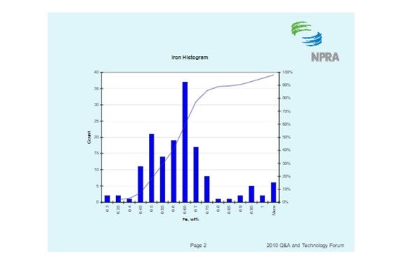
Question 85: What is the typical range that you employ for iron content on FCC equilibrium catalyst? What methods are available to determine how iron is accumulated on the catalyst surface? How does the distribution of iron on the catalyst surface impact the FCC operation, yield structure and emissions?
Jeff Lewis (BASF)
The histogram below shows the distribution of iron content for all ecat samples BASF receives. It should be noted that fresh catalyst has an iron content of about 0.55 wt%. The histogram shows that the median ecat iron concentration is approximately 0.62 wt%. This suggests the median contaminant iron level on ecat is 0.07 wt%.
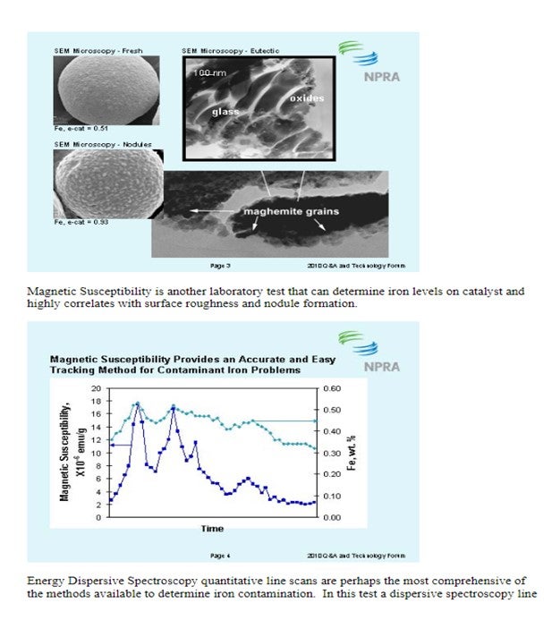
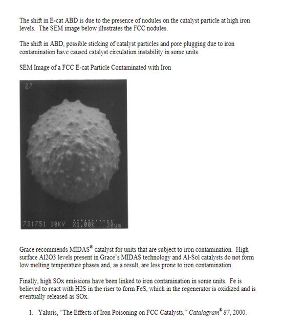
There are several methods available to quantify iron contamination on catalyst. Scanning Electron Microscopy (SEM) pictures are a valuable means to qualitatively assess iron laydown morphology on the catalyst particle. The three images below show varying degrees of iron contamination on a catalyst particle. The first picture shows a fresh catalyst particle that is free of contaminant iron on its surface. The second picture shows a catalyst particle with a significant concentration of iron nodulation on the catalyst surface. The third picture shows a low boiling eutectic formed in the presence of an alkali metal like Ca or Na and is the severest form of iron poisoning.
David Hunt (Grace Davison)
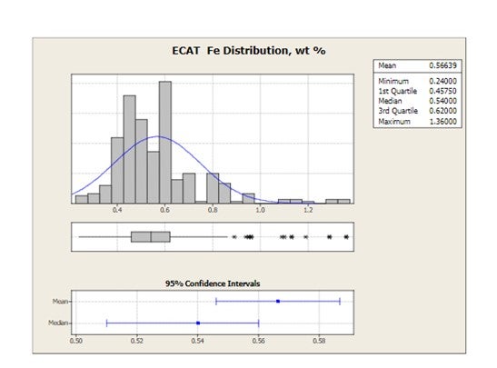
Grace receives E-cat samples for most of the FCC units operating worldwide. The figure below shows the distribution of average equilibrium catalyst Fe levels for 2010 for all FCC units that have provided E-cat samples to Grace. Mean Fe levels are 0.57 wt% and the highest Fe level in one unit is 1.36 wt%.
Iron can be detrimental to the unit in many ways including bottoms conversion, catalyst circulation stability and SOx emissions.
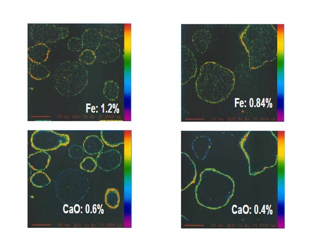
Yaluris (1) showed using an Electron Probe Micro-Analysis (EMPA) technique that iron from organic iron sources is primarily a catalyst surface contaminant. Yaluris also used scanning electron microscopy and optical microscopy techniques to confirm Fe is a surface contaminant. The figure below is an EMPA image of an FCC catalyst particle cross section. Warmer colors on the surface of the particle confirm that Fe and CaO are primarily surface contaminants. EMPA Image of Two FCC Catalyst Particles
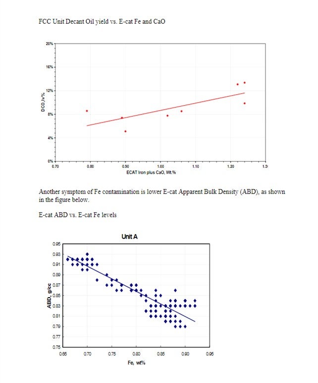
Yaluris (1) discussed how Fe contamination can lead to pore closure and nodule formation. The presence of Na and CaO can act as fluxing agents, aggravating the effect of Fe. The figure below shows Decant Oil or Main Fractionator bottoms yield vs. E-cat Fe plus CaO levels. Decant Oil increases at the higher contaminant levels due to the damaged catalyst pore structure.
Year
2010
Process
Question 13: Severe fouling of diesel and gas oil hydrotreating preheat exchangers has been a growing problem. In your experience, what are the causes and how can these be prevented? Have you tried antifoulant injection in this service?
Dan Webb (Western Refining)
Fouling of the heat exchanger train is sometimes a problem particularly when processing cracked feed stocks. The fouling is often caused by polymer like compounds (gums) that form when petroleum distillates come in contact with air. When heated olefinic compounds react with absorbed oxygen to form gums that deposit in the preheat train.Iron scale and other particulates in the feed often adhere to these gums to produce severe fouling that restricts unit capacity and accelerates heat exchanger corrosion rates. Typically, every effort is made to avoid air ingress into any of the unit feed stocks. Fouling precursors may also be present in straight run feed stocks in the form of certain chemical contaminants that may be present in the crude or inadvertently introduced in an upstream process unit. Some precursors such as amines, carboxylic acids, and carbonyls form gums without air ingress into the feed. Antifoulants have been used successfully to mitigate fouling caused by these compounds in addition to mitigated fouling caused by oxygen contaminate cracked feed stocks.
Michael Chuba (Sunoco)
Typically distillate hydrotreaters exchanger fouling has been associated with cracked stocks that contain olefinic material and trace amounts of O2 coming in with the feed from tankage. In addition to oxygen-initiated polymerization, other impurities can lead to free radical formations that can promote polymerization reactions. These impurities include certain nitrogen and sulfur compounds well as some metal ions including iron, calcium, and magnesium.
In addition to free radial polymerization, condensation polymerization reactions can also result in fouling. In this route, two radicals can react to form a larger molecule. The new compound can continue to react and grow until it precipitates out of solution forming deposits.
What I would like to present here is an example of fouling we had on one of our units and how we have significantly reduce fouling via a simple jump over line.
Prior to conversion of this unit to ULSD the unit processed a mix of virgin and cracked distillate stocks. Historically this unit had exchanger fouling that was attributed to the presence of the cracked stocks. When the unit was converted to ULSD the cracked stocks were removed. The resulting feed was a 50:50 mix of direct rundown material from the crude unit and tankage. As a result of this change in operation it was anticipated that the fouling rate would decrease, however, during actual operation the fouling rate actually increased.
An initial program to address the problem included detailed analysis of the various feed stream followed by a targeted antifoulant chemical injection program. Results were somewhat effective but still left significant room for improvement. Continued investigation into the problem targeted O2 contamination coming from the material coming from tankage. The intermediate distillate tanks are cone roof design which would be relatively costly to convert to blanketed tanks. As a first step it was decided to install a jump over from the tank inlet line directly to the suction of the tanks’ transfer pumps. With this simple connection the average volume of material actually drawn from the tanks dropped dramatically.
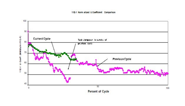
This plot shows the impact on the heat transfer coefficient of the feed effluent exchanger as a result of this simple jump-over. The pink plot represents the previous cycle. At about ¼ of the cycle the jumpover line was installed. At this point significant fouling had already occurred. The discontinuity in heat transfer coefficient a week or two later was the result of a power failure. It is suspected that the rapid depressurization dislodges some of the fouling material thereby improving the heat transfer when the unit is re-streamed. This same response has been seen in previous emergency shutdowns. The green plot represents the current cycle which started with a clean set of exchangers and operation of the jumpover in service from day 1 of the cycle. As can be seen this simple jumpover has significantly reduced the rate of fouling compared to previous cycles. Since the only change was the potential ingress of O2 from the tank, this project confirmed the impact O2 had fouling.
Gregg McAteer (Nalco Company)
Fouling can be a serious problem in hydro-desulfurization (HDS) units because of their importance in producing fuels that should meet environmental specifications. Fouling can limit a unit's ability to maintain a specific feed rate or meet an extended turnaround date. It can greatly influence product quality as well as energy consumption, and catalyst or equipment life. Stricter limits on sulfur and aromatic content of finished fuels make fouling control even more important today. To achieve today’s limits of 0.05 wt.% for diesel, refiners must increase severity of refining operations, which often worsen fouling. Fouling ultimately necessitates shutdown and extensive maintenance, a costly process, both in terms of maintenance expenditures and lost production. Causes of fouling in diesel and gas oil hydrotreaters are both organic and inorganic in nature. The organic foulants are primarily gums formed as a result of processing cracked material and accelerated if the material is exposed to oxygen at any time. Antioxidants and/or antipolymerants are used to reduce the formation of gums and dispersants are used to keep any gums already formed from growing in size.
In one case an antifoulant program utilizing both an antioxidant and a dispersant was applied to a gas oil hydrotreater that normally fouled enough to require a shut down after an average of 440 days. The antifoulant program started on a fouled system and showed
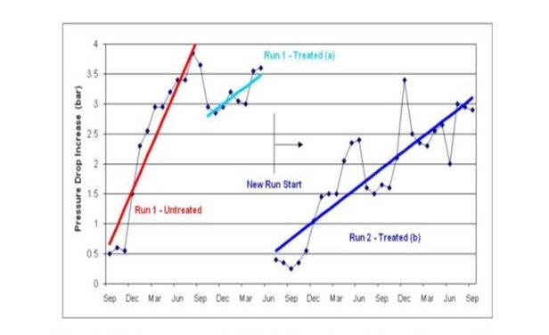
a slight recovery of pressure drop. After a shutdown they started again and achieved a 1300 day run (see graphic below).
“Run 1” is shown in red and light blue. The red trend shows the steep increase in pressure drop during normal operation (without antifoulant program). The light blue trend shows the antifoulant program started, saw a small decrease in pressure drop, and then the unit was brought down for a regeneration. “Run 2” is shown as the dark blue trend and shows a lower fouling rate and longer run length with the antifoulant program. Customer estimated the ROI to be between 400-500%.
Phil Thornthwaite (Nalco Company)
Foulants typically found on the feed side of the preheat exchangers include various gums or polymers, iron sulphide and salts.
The organic fouling due to gums & polymers results from the polymerization of unstable species in the unit feed. The problematic species include olefins (generated in cracking processes), organic acids, mercaptans, ketones, aldehydes, phenols, organo-nitrogen and organo-sulphur compounds. Therefore, in order to determine the risk of organic fouling for a particular feed stream, detailed analysis for the problematic species can be useful guide in evaluating fouling propensity and mitigation strategies.
A typical level for concern for each problematic specie is outlined below:
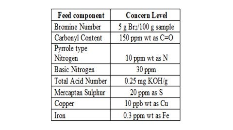
Another key factor to consider is the oxygen content of the feed stream as this can promote the polymerization of various unstable compounds, particularly olefins. Therefore, it is good practice to exclude oxygen from feed storage tanks by ensuring tank seals and vents are in good condition and through the use of a nitrogen blanket. However, this method is ineffective with streams already exposed to oxygen since the nitrogen blanket will have no effect on oxygen reaction products such as aldehydes, peroxides and hydroperoxides.
Inorganic fouling is mainly caused as a result of iron sulphide that can either be carried from upstream units or generated in-situ in the preheat exchanger network. However, the latter is not so common since refiners choose the metallurgy to mitigate against sulphidic corrosion in most cases.
In order to mitigate and control fouling in the preheat train, chemical dispersants and antipolymerants are used. The properly selected dispersant will act upon the organic polymers by keeping them finely dispersed within the feed stream thus minimizing the risk of deposition on the exchanger surfaces. Likewise, dispersants can also prevent deposition of FeS by keeping them dispersed in the feed stream.
Antipolymerants act by disrupting the propagation and chain extending stages of the free radical polymerization reactions and by increasing the rate of termination. This will limit the rate of polymer growth within the preheat system. They will also minimize carbonyl formation which will in turn disrupt condensation polymerization reactions.
The key to monitoring the program effectiveness is through accurate monitoring of the preheat exchanger network. If the fouling results in a limitation of heat transfer efficiency, then a temperature survey of the exchanger network is carried out and this data is entered into a rigorous thermodynamic process model, such as Nalco’s MONITOR® program. This model will then use the plant data to calculate actual and normalized exchanger duties and heat transfer coefficients plus it will calculate the normalized furnace inlet temperature (NFIT). A successful antifoulant program will limit the decay in the NFIT and will generate significant returns for the refiner by improved energy efficiencies and optimized unit operation.
Robert Wade (ART)
We have not had success reducing fouling effects by adding antifoulants. It is our experience that adding antifoulants at best treats the symptom of the problem, and at worst further contributes to localized and downstream fouling. We recommend that the source of the fouling contaminant be identified through analysis and addressed at the source. If this is not possible then we revisit the basic design of the heat exchanger in question and ensure that it is operating in a shear controlled flow regime so that fouling effects are minimized
Year
2010
Process
Question 38: What measurements and criteria do you use to decide when to change your gas and liquid chloride absorber material? How do you determine the selection of absorber material?
John Clower (Chevron)
For both gas and liquid service, Chevron monitors the inlet HCL/Total Chloride and replaces the adsorbent/molecular sieve based on material balance loading of chloride on the adsorber media. Chevron does monitor adsorbent outlet HCL/Total Chlorides, but as a best practice will change the adsorbent material before vendor maximum loading if breakthrough has not occurred. Spent adsorbent will become acidic and pass chloride as organic chloride to the downstream processes. Organic chlorides are difficult to detect by conventional tubes in gas service and will form HCL in downstream processing units.
This performance-based approach is not without problems, e.g., the accuracy of both chloride measurements and represented adsorbent capacity, and therefore requires a trial-and-error
approach.
Represented capacity of any chloride trap material will have been set the vendor to minimize high acidity conditions that lead to organic chloride and polymer (red/green oil) production. Commercially there are four main types of chloride adsorbent material available:
•Alumina
•Modified/Promoted Alumina
•Molecular Sieve
•Metal Oxide
Each of these materials is used in Chevron Refineries and joint ventures. Each adsorbent type will have various properties that can be used in making a decision on application:
•Total chloride capacity (HCL and Organic)
•Reactivity – potential for organic chloride and red/green oil formation
•Interferences (e.g., Sulfur)
•Cost per pound of chloride removed
Also, the design of the vessel used is important (L/D for adequate flow distribution, contact time) and can result in shorten life versus predicted breakthrough. Selection of adsorbent versus service will usually be made on a cost per pound of chloride removed.
Janel Ruby (Johnson Matthey Catalysts)
Chloride can be removed from streams using various products. These chloride guard products can differ in the way they are manufactured and in the way they work in certain applications, so it is important to choose the right one for your needs. The most common products are chemical absorbents or promoted alumina adsorbents. Chemical absorbents remove chlorides by irreversible chemical reaction, meaning that the chloride is chemically bound within the absorbent. Chloride removal in promoted alumina is accomplished mainly by adsorption in which hydrogen chloride is adsorbed onto the alumina surface. Both types of beds are non-regenerable and require change-out at chloride breakthrough.
When determining which product is right for a particular service, it is important to evaluate the operating parameters of the chloride guard bed. The location of the bed in the reforming flow sheet, the operating temperature of the bed, and the normal and maximum inlet chloride levels are important factors to consider when selecting an absorbent type.
Promoted alumina products are available for liquid and gas services. Promoted alumina can work over a range of operating temperatures but chlorides that are adsorbed onto the material may desorb at higher temperatures which will decrease the effectiveness of the product in these regimes. These products also have a lower chloride capacity usually ranging from 12 to 15% wt/wt, and require a high change-out frequency. An area of concern when utilizing promoted alumina materials is the formation of undesirable side products. When the chloride binds to the alumina surface of the guard material, it creates surface acid sites. The acidic surface of the material can catalyze side reactions and lead to the creation of organic chlorides or high-molecular weight hydrocarbons called “green oils.” Green-oils not only foul equipment, but also the guard bed itself, which can cause difficulties in bed discharge (increased purge time) and disposal.
Chemical absorbents are the most favorable option for chloride removal. These products are available for use in liquid and gas services. Chemical absorbents work over a wide range of temperatures. These products have high chloride pick-ups, for example PURASPECJM 2250 is a mixed metal oxide chemical absorbent which can achieve a chloride capacity of 30% wt/wt in non-fouling, gas phase applications. As previously stated, these products remove chloride through an irreversible chemical reaction. The alumina structure present in these types of chemical absorbents acts only as a binder which minimizes the tendency for unwanted side reactions. PURASPECJM 2250 can commonly be employed with the use of just a single guard bed.
There a few other considerations surrounding chloride guard bed materials. It is important to avoid two-phase flow in these beds as this will affect the performance of the chloride guard. Both promoted alumina products and chemical absorbents have a higher pick-up in gas phase, non-fouling and non-wetting applications. In liquid applications, diffusion through the liquid film around the chloride guard particle is the rate limiting step and capacities are generally lower than gas phase duties because of the mass transfer effects. Chemical absorbent products, PURASPECJM 6250 and PURASPECJM 6255 were designed to address this concern. These products have a high capacity and specific pore structure to allow improved removal capacity. They are comprised of the same chemical formulation and micromeritic properties but represent two differing particle sizes; PURASPECJM6255 is manufactured as a smaller sized sphere. The smaller size provides better performance as this minimizes the liquid film through which the HCl must diffuse, reducing the depth of the mass transfer zone and leads to higher average chloride pick at the point of HCl breakthrough.
The presence of HCl or organo-chlorides (RCl) in the exit stream of the chloride guard bed will indicate it is time to change out the material. The life of the guard depends on how the bed(s) is configured and what type of product(s) has been installed. Unless the bed needs to be shut down for inspection or is involved in a larger turnaround plan, chloride breakthrough will be the main reason for a shutdown to replace product. Regular testing for chlorides in the exit stream will help to determine when change out is needed. In applications with longer life cycles (years) testing may only be needed monthly until the bed is getting closer to its expected change-out interval. In applications with shorter life expectancies (months), the frequency of testing should be at least weekly.
Throughout the life of the bed, it is important to measure the HCl and RCl levels both inlet and exit the chloride guard beds. It has been shown that when promoted alumina is used for HCl removal, it catalyses the conversion of HCl to organic chloride species that can then slip from the bed. If the operator is only measuring for HCl then this chloride slip can go undetected until downstream issues occur. Chlorides passing through the bed can cause corrosion of downstream equipment and formation of ammonium chloride that cause fouling and blocking of equipment e.g., stabilizer columns, exchangers and compressors.
Year
2010
Process
Question 43: What are your best practices when shipping ecat, fines, feed, and slurry to suppliers for testing? Please also comment on some best practices for sampling equilibrium catalyst.
TODD HOCHHEISER (Johnson Matthey)
When shipping ecat or fines, an appropriate sample container should be used. Catalyst suppliers will typically provide refiners with sample containers if needed. Catalyst shipping containers should be made of plastic or metal. Glass containers are not recommended due to potential breakage but can be used with appropriate packaging. A screw top lid is preferred over a snap on lid sometimes found on metal containers. Prying opening a snap on lid can result in personnel dust exposure. Catalyst samples should not be shipped in plastic sandwich bags or other containers not designed for catalyst service.
JM has found that metal sample containers with a screw top lid are best when shipping low vapor pressure hydrocarbon samples. A best practice is to place the sample container in a plastic bag containing adsorbent pads. These pads should minimize the chance of hydrocarbons leaking out of the box if the sample container leaks.
For hazardous catalyst and hydrocarbon samples, a GHS complaint label must be placed on the sample container. The safety data sheet must also be included with the shipment. Most catalyst suppliers prefer for a safety data sheet to be included even if the sample isn’t considered hazardous. Other regulations and requirements may apply especially for sample shipments between countries.
Common sense precautions are also recommended. Some examples are shipping only the quantity of sample that is required, packaging in strong boxes, and using labels with high quality adhesive. Our lab has received sample boxes containing multiple ecat samples and multiple labels that are no longer attached to the sample containers. Clearly identifying the date of the ecat samples is critical for unit monitoring.
For any sample that is shipped, it is recommended that a company representative certified under DOT or applicable regulations be involved in the packaging and shipping process. Carriers also have specific requirements for shipping hazardous material.
KEN BRYDEN AND LUIS BOUGRAT (W. R. Grace & Co.)
For all samples, it is important to provide a safety data sheet (SDS) when shipping the sample and to follow appropriate Department of Transportation (DOT) and International Air Transport Association (IATA) rules when packaging and sending the sample. Samples should not be sent by U.S. Mail or any service that transfers to U.S. Mail. Based on our experience receiving and testing thousands of customers Ecat and hydrocarbon samples each year, Grace has the following suggestions on best shipping practices.
Ecat and Fines Samples
For Equilibrium catalyst (Ecat) and fines samples, we have found that for routine testing a 500 mL screw top plastic container is an ideal size. Grace provides complimentary Ecat Express containers for this purpose. Screw-top metal containers are another packaging option for Ecat. Glass containers are unsuitable for Ecat since they tend to break in shipment. Containers with paint can lids are unsuitable since the lids tend to come off during shipment and spill catalyst. Bags are also unsuitable containers since they tend to leak. For any container, do not put any tag, string or wire between the cap and the container lid since they will compromise the seal and cause leaking. For large quantities of Ecat, we have found that five-gallon (or 20 liter) plastic screw top buckets are good containers.
For Ecat and fines samples, proper labeling is important in making sure the desired tests are done and reported. At a minimum, samples should be labeled with the following information:
-
Refinery or company name.
-
Refinery location. For example, city and state.
-
Unit Name: Especially important if there is more than one FCC unit at the refinery location.
-
Sample Date: The date that the sample was collected.
-
Sample ID: (Optional) A sample number or name, for your reference.
-
Sample Type: for example, Ecat, fines, purchased Ecat, non-routine, etc.
As part of the complimentary Ecat Express kits, Grace provides container labels that already have the refinery name and unit written and barcoded on the label.
Feed and Oil Slurry Samples
For routine analytical testing to measure the properties of feed or oil slurry samples, a 16-ounce (or 500 mL) sample size is preferred. In shipping hazardous materials, proper packaging and labeling is essential to ensure compliance with the appropriate regulations. This will prevent fines from the carrier and delays in your shipment. In addition, poorly packaged samples can leak, which results in the sample being compromised and thus unsuitable for analysis. There are many good packaging systems available from suppliers that may be chosen to meet the packaging requirements of IATA and CFR49. Which system to use has to be determined by each individual shipper for their samples. The most common system that we see customers use is a 4GV shipper where the hydrocarbon sample is packaged in a metal can, which is then placed inside a plastic bag with an absorbent sleeve. The entire assembly is then placed in a certified cardboard box. It is important to make sure that the lid is screwed on securely. We occasionally receive leaking samples where the container lid vibrated loose in shipment. In preparing containers, make sure tags and wires from labels are not in the thread area of a cap. A string or wire from a label tag put into the sample container, with the cap sealed over it, will act as a wick. This will always cause leaking. Container types that we have noted problems within the past are a) paint cans- the lids often pop off during shipment, and b) glass bottles- they have a tendency to break during shipment.
As with Ecat samples, labeling of feed and slurry oil samples is important. The container should be labeled with the material identity and the appropriate Global Harmonized System (GHS) hazard symbols. Additionally, the sample should be labeled with the following information:
-
Refinery or company name
-
Refinery location: for example, city and state
-
Unit Name: especially important if there is more than one FCC unit at the location
-
Sample Date: the date that the sample was collected
-
Sample ID: (Optional) a sample number or name, for your reference
-
Sample Type: for example, feed, oil slurry, etc.
Process Ecat Sampling
Routine and representative sampling of the circulating Ecat inventory represents a critical part of FCC performance monitoring and optimization. Samples of the circulating inventory should be collected from a fluidized and accessible section of the unit to enable representative sampling of the catalyst system. From a safety standpoint, regenerated catalyst represents an inherently safer sampling source than spent catalyst due to the lack of entrained hydrocarbons and the lower coke concentration along the surface of the catalyst. However, the process temperatures associated with regenerated catalyst are significantly higher than those of spent catalyst and should be mitigated accordingly.
The regenerated catalyst standpipe represents the most common sampling location due to the continuous catalyst flow and accessibility associated with this standpipe. Although the flowing catalyst is well fluidized within this type of standpipe, it is important to properly fluidize the sampling manifold as well when obtaining a catalyst sample. Plant or instrument air are the most common fluidization media for regenerated catalyst sampling stations, which can also be equipped with steam connections to serve as blast points for line plugging troubleshooting. An air or steam purge into the process should be maintained at all times across the standpipe sampling nozzle to prevent catalyst ingress and nozzle plugging. The fluidization medium should correspond to a reliably dry source to prevent potential catalyst agglomeration issues throughout long-term operation. The sampling outlet nozzle should be purged prior to lining up the sampling line to the process to ensure that the manifold is clear of fouling and to confirm that the sample fluidization medium is available and properly dry. The key considerations and best practices for the Ecat sampling process, among others, are as follow:
-
Field personnel should be equipped with all necessary PPE prior to collecting the Ecat sample. Contact your catalyst vendor if any additional feedback or specific PPE guidelines are required.
-
Any potential impacts on instrument readings or safety interlocks by the Ecat sampling process should be thoroughly identified. Ecat sampling activities should be communicated to the board operators prior to starting the sampling process to help ensure that instrument and safety interlock functions are not compromised while sampling.
-
Ensure that the sampling container or recipient is adequately rated for the normal process temperatures associated with the circulating Ecat inventory. The sample containers used for shipping are not typically rated for these elevated temperatures. Metallic containers are typically required to accommodate Ecat sampling.
-
The sampling valve and the sampling outlet nozzle configuration should, ideally, enable sample collection without exposing field personnel to catalyst and entrained flue gas at the high process temperatures. A remote point where the operator can operate a HIC (Hand Indicate Controller) valve to take the sample in line of sight of the sample station but a safe distance away is practiced by several refiners. The sampling recipient can be attached to a long metallic or high-temperature-resistant handle to help mitigate personnel exposure to high temperatures throughout the sampling procedure.
-
Sufficient sample flow should be established to enable collection of a representative Ecat sample. Insufficient purging of the sampling manifold with the flowing Ecat can lead to non-representative or compromised results due to the presence of stagnant Ecat from previous sampling rounds, or other similar contamination sources. Collection of a slip stream during continuous Ecat flow through the sampling line tends to yield a more representative sample than collecting a vial sample from a drum or (large container) of Ecat sample inventory.
-
Excessive superficial velocities through the sampling manifold should be prevented while sampling to help mitigate potential erosion and attrition issues. Excessive catalyst attrition through the sampling line can lead to false PSD profiles for the circulating catalyst inventory that can prompt unnecessary troubleshooting activities. Adequate velocities through the sampling nozzle also help reduce turbulence and dust as the flowing Ecat reaches the sampling container, thus preserving as much of the fines content present in the circulating inventory as possible.
-
A pint of Ecat sample is usually sufficient volume to accommodate routine lab testing for process monitoring purposes. Excess Ecat sampling volume should be properly handled and discarded via spent catalyst drums or disposal lines routed to the spent catalyst hopper, if available.
-
Ecat samples should be allowed to properly cool before filling the corresponding shipping containers. Windy or wet environments should be avoided for the cooling period to avoid altering the physical properties of the Ecat sample.
The guidelines and best practices previously referenced should be followed when shipping the Ecat sample containers. Board operators, unit engineers and other supporting staff for the FCC complex should visually inspect Ecat samples before the sample is shipped to the catalyst vendor. Visual inspection can help qualitatively gauge the health of the circulating catalyst inventory – especially with respect to coke on regenerated catalyst (CRC), drastic PSD shifts, and/or potential Fe poisoning contamination – well before the corresponding lab results become available.
Year
2019
Process