Concurrent Breakout Sessions
Learn More.
Session Start End
-
TRAGESSER (KBR)
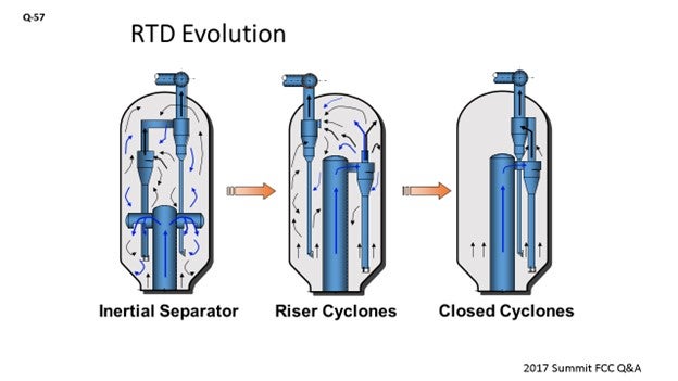
Advanced Riser Termination Systems are, by definition, a way to quickly terminate the reactions occurring in the riser. The goal is to rapidly separate the catalyst from the hydrocarbon vapors and then quickly minimize the time the hydrocarbon vapors are at reaction temperature before being quenched in the main fractionator. If these two goals are accomplished, post-riser reactions are minimized. The most undesirable of these reactions is thermal cracking reactions that reduce gasoline yield and increase dry gas make.

Riser termination systems have evolved from the early days of riser cracking that commonly used inertial separators where the riser hydrocarbon product and catalyst were discharged into the reactor where non-desirable post-riser cracking reactions occurred. The next major advancement was to add efficient catalyst separation devices – such as riser cyclones to the end of risers – to quickly separate the catalyst from the hydrocarbon products. While this terminated that catalytic cracking, it still allowed the hydrocarbons to undergo thermal cracking reactions as they were discharged into the large disengager vessel, which resulted in long hydrocarbon residence times.
Just a little history: In the mid-1980s, Mobil recognized a need to eliminate these undesirable thermal cracking reactions that occurred in disengager and developed the first Advanced Riser Termination System – commonly called ‘closed cyclones’ – where they coupled the riser cyclones directly to the upper cyclones. Mobil pioneered the use of advanced riser termination and installed it in eight of their own units in the late 1980s. In 1990, KBR formed an FCC alliance with Mobil and began licensing the technology. While Mobil’s development and commercialization worked out many of the issues prior to KBR’s involvement, there have been improvements in the technology since then, which I will discuss.
Many of the improvements in KBR’s 27 years of experience have been operational-related. For example, we have been able to reduce startup steam requirements by lowering the required riser cyclone inlet velocity requirement without any negative impact.
One of the keys to a successful startup is to avoid overloading the cyclone system during initial steam circulation. This means making small increases in catalyst circulation and letting things stabilize before making another increase. Once feed is in the unit and cyclone velocities are increased, then the system becomes very stable and resilient.
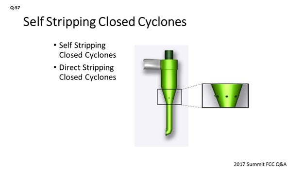
One improvement that has been developed is referred to as ‘self-stripping closed cyclones’ where small holes are placed in the lower cone section of the riser cyclones where the stripping steam flows through. The purpose of this modification is to eliminate the small 2% underflow of hydrocarbon that is normal for a closed cyclone system. This improvement further reduces thermal cracking, thereby increasing the gasoline yield. Another version of this process is referred to as ‘direct stripping’, where external steam is supplied separately to the cone section and the normal cyclone hoods are maintained. This gives the operator flexibility to optimize the cyclone stripping steam.
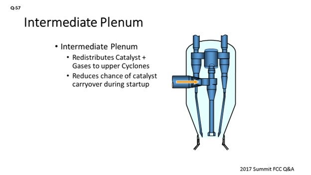
Another change we are implementing on newer projects is to use an intermediate plenum between the riser cyclones and the upper cyclones, as shown in the figure. The main reason for this change is that it allows the catalyst to be redistributed to the upper cyclones and makes the system more resilient to an upset of a primary riser cyclone. Another advantage is that it allows the use of a different number of upper cyclones than that of the riser cyclones. This can have a layout advantage, especially on larger units where we can have two large riser cyclones and maybe four or five upper cyclones. Due to the ability to use smaller upper cyclones, the required vertical space will be reduced as a result of the cyclones being shorter compared to the layout of a system with two large upper cyclones.
MALLER (TechnipFMC Process Technology)
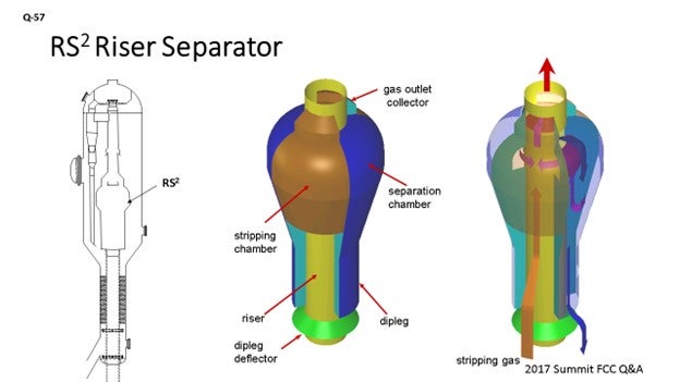
The evolution of our technology at TechnipFMC is similar. We initially had the inertial separator, which had vented gas tubes to the upper reactor section to be close to the reactor cyclone inlets. Now we have a totally closed system. What is shown on the slide is the RS2 (riser separator) technology. One important point I want to make is that the ability to maintain ease of operation during startup, shutdowns, and upsets – without the risk of massive catalyst carryover – is important. With this technology, the diplegs are very large and not prone to flooding. It is essentially an inertial separator, so there is not a high velocity requirement to maintain adequate separation; therefore, there are no emergency steam requirements for startup. If we get enough velocity to transport catalyst, it is enough velocity to achieve good separation. Therefore, the RS2 does not experience any massive catalyst carryover events during startup.
Our recent improvements: We are now learning that we have more units go through turnarounds. Unfortunately, the cycle for these lessons on reliability is every five years when a unit shuts down. We are currently making mechanical and reliability improvements to each situation when we see the requirement. We have made some changes to the slip joint design that allow for the independent thermal expansion of the lower section versus the upper section. We are also working continually with the cyclone vendors to try to improve the overall system efficiency for catalyst collection.
DAVID HUNT [Shell Global Solutions (US) Inc.]
I would like to add that in the FCCs we operate at Shell, as well as at several of our third-party customers, the cyclone technology uses what we call a ‘coke catcher’ which keeps coke from falling into the reactor cyclone dipleg and potentially blocking the dipleg during the run. Other developments in our Shell cyclone system include the use of a vortex stabilizer in the secondary cyclones to control the vortex and avoid dust bowl/dipleg erosion.
ALEX MALLER (TechnipFMC Process Technology)
The primary goal of a modern riser termination system which considers the close coupling of the primary and secondary separating devices is the reduction of residence time and, thus, the minimization of undesirable thermal cracking reactions. This post-riser cracking usually translates to dry gas yield at the expensive of other, more valuable products. By revamping an older type of system to a close-coupled advanced system, we have seen a typical reduction of dry gas yield of about 20% with corresponding increase in liquid product volume.
Another important goal of a modern riser termination system is the efficient separation of catalyst particles from the reactor gasses, implemented with the aim of preventing excessive catalyst accumulation in the main fractionator bottoms circuit. This goal is important for all modes of operation, including startup/shutdown and transient periods. The system we have now is extremely efficient during normal operation, but most notably retains very high levels of efficiency at all times when catalyst is circulating. The primary separator is a positive pressure type, and the diplegs are very large and not prone to flooding. This arrangement ensures that any velocity sufficient to transport catalyst up the riser is enough to achieve adequate separation. No emergency steam is required. No massive catalyst carryover events have occurred on any of our installations.
Our focus for technology improvements in recent years has focused on the reliability, as well as incremental improvements to the above-mentioned primary goals. For reliability, we have updated the design for the slip joint that ties together the upper cyclone portion of the system to the lower termination device. The new slip joint design has proven to be extremely robust without any issues reported on any units.
MATTHEW WOJTOWICZ (Honeywell UOP)
Evolution of UOP’s Vortex Separation Riser Termination Technology
Before evolving to the vortex separation riser termination technology, UOP gained experience with all types of riser termination technology. Since 1983, UOP’s designs for riser termination devices have focused on reducing the post-riser vapor residence time in the reactor vessel. Since many of UOP’s efforts have involved technology upgrades in existing units (revamps), a variety of mechanical systems have been implemented to accommodate the wide variety of existing reactor sizes and styles. All of the UOP designs emphasize operating flexibility and mechanical reliability.
UOP’s current riser termination design incorporates the state-of-the-art vortex separation technology to minimize the vapor passing into the reactor vessel and thereby minimize non-desirable reactions.
In 1995, UOP commercialized the VSS™ (vortex separation system) technology which was specifically designed for higher capacity units with an internal riser while maximizing hydrocarbon containment, operating flexibility, and mechanical reliability. UOP’s VDS™ technology offers the same benefits for units with external risers. The VSS technology has evolved since it was initially commissioned in 1995. These enhancements have further improved hydrocarbon containment, operating flexibility, and mechanical reliability. A few of these enhancements are summarized below.
Hydrocarbon Containment Advantage
Vortex separation technology represents the highest hydrocarbon containment technology available, as it provides more than 99% containment of the hydrocarbon product vapor relative to only 94 to 97% for the next best system (direct-connected cyclone systems). The containment advantage is based on the quantity of hydrocarbon product vapor that is entrained with and adsorbed on the catalyst discharging from the first-stage cyclones. This hydrocarbon is equivalent to as much as 6% of the riser vapor. The hydrocarbon carryunder spends relatively long residence times in the reactor vessel before finally exiting out through pressure equalizing tubes.
The vortex separation technology is designed to eliminate the hydrocarbon flow that exits at the bottom of the conventional riser separation devices, as well as efficiently separate the catalyst from vapor exiting the riser. The top of the stripper and the bottom of VSS chamber are integrated with each other thereby allowing the riser and stripper vapors to be contained. These vapors are prevented from entering the reactor vessel where they can undergo nonselective thermal cracking due to long residence times. The containment advantage of the VSS technology is illustrated in Figure E-1. Since the original implementation in 1995, the design has been tweaked to further improve hydrocarbon containment. The bed level has also been optimized further improving yields.
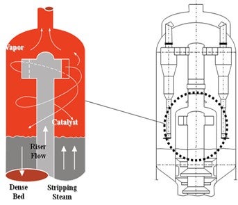
Figure E-1. VSS Hydrocarbon Containment Advantage
The superior hydrocarbon containment performance of the vortex separation technology provides improved yield performance over all competitive systems. The hydrocarbon not contained by the primary separation device undergoes significant nonselective thermal cracking due to long residence times in the reactor vessel. This results in a significant increase of dry gas, as well as major losses of gasoline, LCO (light cycle oil), and overall product olefinicity. Dry gas production – at the expense of the gasoline and LCO production – represents an opportunity loss which limits the profitability of the FCC unit. Additionally, the reduced olefin content of the gasoline will result in a reduction in the octane of final FCC gasoline product. The VSS technology reduces nonselective, post-riser cracking and can help maximize the profitability of the FCC unit through improved gasoline selectivity, improved gasoline octane, and reduced dry gas.
Operability and Reliability Advantage
UOP has significant experience within fluid catalytic cracking technology and has garnered a reputation for designing technologies for maximum operability and reliability. The vortex separation technology offers clear operational advantages over previous generation riser termination devices (RTDs), including ease of startup, turndown flexibility, reduction in reactor coke formation, and reduced incidents of severe erosion of internal components.
During FCC unit startups, operations can experience pressure upsets which quickly send large amounts of catalyst into the reactor vessel. Pressure upsets of this kind are known to quickly overload other RTD designs and send large amounts of catalyst to the main column, causing costly high-catalyst makeup rates and problems in the main column or the main column bottoms product. Conversely, the vortex separation technology can easily handle pressure surges and reduce the risk of catalyst carryover through the use of its unique primary separation design. This operational advantage manifests itself as smoother and more robust operation of the FCC unit during upsets and is relatively more forgiving during unit startups.
Not only does the vortex separation technology offer process and operability advantages, but it also can provide several reliability advantages. Coke formation in a reactor is largely influenced by the reactor technology and appropriate use of steam. The coke produced in the reactor space can build up on the reactor walls or refractory, pressure equalization openings, and other flexible joints, which can lead to either equipment failure or increased maintenance costs. The latest vortex separation technology creates a hydrocarbon-free environment in the dilute phase of the reactor by maximizing riser hydrocarbon containment. Coke has been completely eliminated from the reactor annular space. The vortex separation technology has been used as a process revamp improvement, as well as a technology upgrade to address coke formation.
UOP’s design methods include several considerations and features which have dramatically reduced the incidents of severe erosion of internal components over time. Internals are designed with appropriate orientation and velocities to minimize erosion potential in critical areas such as cyclone inlets. UOP also specifies proven refractory- and abrasion-resistant lining materials in these areas which often survive a run with only small sections requiring repair. Utilizing these design methods, the vortex separation technology offers improved mechanical reliability of the reactor internals, improved unit availability, and reduced maintenance costs over the next best RTD alternative. Also contributing to the high mechanical reliability of the technology is the fact that over 95% of the catalyst separation occurs in the low-velocity VSS chamber, meaning that less than 5% of the catalyst will enter the higher velocity cyclones. There are multiple refiners with UOP’s latest VSS technology who achieve 99+% onstream efficiency with minimal maintenance required to internals following a campaign of more than five years.
FOOTE (CHS Inc.)
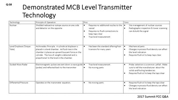
I prepared a few tables about technology and the principle of operation pros and cons of each of the demonstrated level of technologies and main column bottoms level transmitter. Again, it goes without saying that accurate measurement of the main column bottoms level is essential for reliability and safety. First, what I will talk about is nuclear. One of the benefits of nuclear technology is that it does not require any additional nozzles in the vessels. So, if you are looking for redundancy and do not want to go through the expense of installing a nozzle, this is a good option for you. Nuclear also does not require flush connections. Every bit of HCO (heavy cycle oil) flush you put back into the bottom circuit will affect your fractionation, so minimizing HCO flush is a big deal. Nuclear technology also gives you a true level measurement. The drawbacks to nuclear are obviously site management and nuclear sources; but likely, you already have these in your refineries. RT (radiographic testing) inspection and tower scanning can mess up your level indication. Just make sure people are communicating when they are doing x-rays in their work areas.
The next technology is the torque tube. Basically, it is a cylinder that operates inside of a chamber where the fluid exerts a buoyant force on the cylinder. The difference in the weight is detected and corresponds to a level. Torque tube technology has been the standard offering from licensors for years now. The drawbacks to it are that it is a little mechanical; not terribly mechanical, but there are pieces that can fail on it. It also changes in process. Fluid density on startup, shutdown, and malfunction can affect the level measurement. The torque tube also requires flush oil.
The third technology is guided-wave radar. Again, it gives you a true level measurement and has no moving parts. The common pitfall here is probe selection. Make sure your manufacturer knows that there is the potential for solids in these circuits and that he/she gives you the right type of probe. Sometimes the probes can be too tight, and you can plug them up. Guided-wave radar also requires flush oil to keep the taps operational.
The last technology is pressure differential, which is very similar to torque tube. It is a proven technology; but again, it does not give you a true level if you have gasoil, say, at the bottom of the main column on startup.
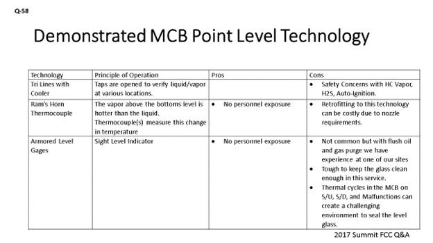
The next slide gives us the Point Level Technology. So, in addition to level transmitters, we also want to have point level indication. For years, the standard from licensors has been the try lines with the cooler. Obviously, the taps are open and you either have vapor or liquid there. The try line taps provide you with the means of telling you where the level is within the column. Obviously, there are safety concerns with try lines because you have H2S vapor and auto-ignition possibilities.
The second technology – Ram’s Horn Thermocouple – is one that I am not sure has been commercially demonstrated in an FCC unit but which I think has been used in crude and in vacuum columns. Basically, the sub-cooled liquid is detected as the level goes up. There is no personnel exposure here. Retrofitting this technology can be costly, because it does require one nozzle for the thermocouple and another one for the ram’s horn drain that goes down below.
Armored-level gauges have also been used. This equipment is not very commonly chosen. With purging, you can keep the glasses clean, although it is tough to do. Also, because of the thermal cycles you run on the startup, shutdown, or malfunction, keeping that glass sealed can be challenging. So, there are some challenges with that technology.
Regardless of the technology we are using, redundancy is important. Right? I think it is best to use two different types of technology, if possible. However, Best Practice is to employ two level transmitters with the selector switch from the main column bottoms level control. For displacers, guided-wave radar, dP transmitters, and redundant transmitters need their own individual taps. So, do not try to put them on one set of vessel taps, because that is a single point of failure. For point level measurement, at least two points should be measured for high and low levels.
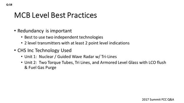
At CHS, we operate our Laurel, Montana FCC. We use nuclear and a guided-wave radar with flush oil, and we use try lines for point level indication. We are strongly considering going to the ram’s horn thermocouples because of safety concerns at that FCC. At our McPherson refinery, we use two redundant level displacers and two armored gauge glasses that have LCO flush and fuel gas flush or fuel gas purge as well. We also have tried lines at McPherson.
MALLER (TechnipFMC Process Technology)
The TechnipFMC standard is a diaphragm-type pressure differential level instrument. We use continuous HCO flushing. We would like to see multiple instruments there for redundancy. I would go as far as to say that three separate instruments should be used. That way, you have the chance that two of them read the same, rather than having to discern which is correct with only two different readings. Also, I like to see a local gauge for field verification, which I have seen successfully applied via magnetic-type float gauges in service.
TRAGESSER (KBR)
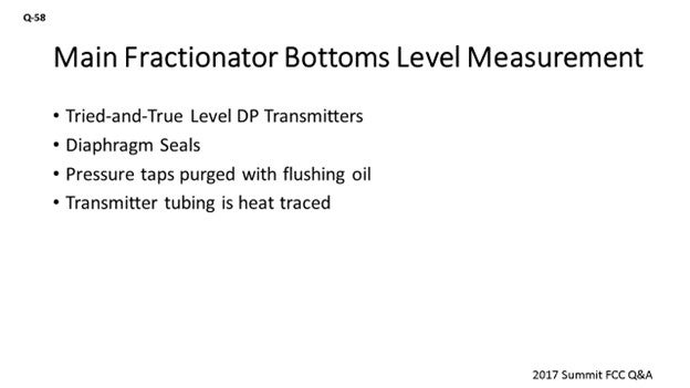
KBR’s normal practice is to offer a tried-and-true method that uses simple level transmitters for main fractionator bottoms. Both level transmitters are pressure differential types and share the nozzles at the vessel. Multiple transmitters are provided for improved reliability. The board operator has the option to switch between the two measurements.
Both level transmitters use a diaphragm seal to prevent slurry and solids from getting into the transmitter.
The main fractionator measurement nozzles at fractionator shell are purged. We use fuel gas to purge the low pressure tap and flushing oil to purge the high-pressure tap. The tubing for the transmitters is electric or steam-traced to minimize the potential for blockage if the purge is lost.
MELVIN LARSON (KBC Advanced Technologies, Inc.)
How far up do you take your top tap on your level transmitter?
MALLER (TechnipFMC Process Technology)
Typically, we have a reduced diameter boot at the bottom of the fractionator and we take the top tap at the top of that area. We do not take it up into the flash zone.
DARIN FOOTE (CHS Inc.)
The following tables list the demonstrated technologies to reliably measure main column bottoms (MCB) level. Regardless of the technology used, it is important to have redundant level indication. The Best Practice is to employ two level transmitters with a selector switch for MCB level control. For displacers, guided-wave radar, and dP level transmitters, redundant transmitters should be on independent vessel taps. There are benefits to having two different level technologies employed. For point level measurement, at least two points should be measured for high and low levels.
Table 1. Level Technologies for Main Column Bottoms Level Transmitters
|
TECHNOLOGY |
PRINCIPLE OF OPERATION |
PROS |
CONS |
|
Nuclear |
Shielded radioactive isotope source on one side and detector on the opposite |
|
|
|
Level Displacer (Torque Tube) |
Archimedes Principle: A cylindrical displacer is placed in a level chamber. As fluid rises in the chamber, it places an upward buoyant force on the cylinder. The loss of weight is detected and is proportional to the level in the chamber. |
|
|
|
Guided-Wave Radar |
Electromagnetic pulses are sent down a wave guide (probe) and reflected back to the transmitter. |
|
|
|
Pressure differential |
Operates on the manometer equation. |
|
|
Table 2. Demonstrated Methods for Point Level Indication in the Main Fractionator Bottoms
|
TECHNOLOGY |
PRINCIPLE OF OPERATION |
PROS |
CONS |
|
Try Lines with Cooler |
Taps are opened to verify liquid/vapor at various locations. |
|
|
|
Ram’s Horn Thermocouple |
The vapor above the bottoms level is hotter than the liquid. Thermocouple(s) measures this change in temperature. |
|
|
|
Armored Level Gages |
Sight Level Indicator |
|
|
At our Laurel, Montana FCC, we use nuclear and guided-wave radar for redundant indication and try lines for point indication. We are strongly considering getting rid of our try lines and replacing them with ram’s horn thermocouples due to safety concerns. In our McPherson, Kansas FCC, we use redundant level displacers and two armored gage glasses for point indication.
ALEX MALLER (TechnipFMC Process Technology)
We use diaphragm-type pressure differential level instruments with continuous HCO flushing oil provided to the connection at the vessel. Multiple instruments are typically used to provide redundancy and some confidence in the readings. A magnetic-type float gauge can also be provided for verification in the field, but it should be insulated, steam-traced, and provided with continuous flushing. With these arrangements, level measurement at the main fractionator bottoms is not typically a big issue. Some units have applied nuclear-type instruments successfully for this service, but it is not our standard to do so.
FEDERSPIEL (W.R. Grace & Co.)
Evaluating an FCC catalyst reformulation is not something you are able to do overnight. It is a long commitment to post-audit the catalyst reformulation. Because of that, preplanning really is critical. Right? You want to make sure that you plan out for the trial in a manner that will let you do your post-audit effectively. You will want to define the objections and constraints very clearly in the beginning of the trial and establish sample and data collection, both the timing on that and the methods. Then, you should develop an evaluation plan. What does success look like for this reformulation? Because of the time commitment it takes to do a catalyst trial, the average age of catalysts inside an FCC unit could be anywhere from 20 days. This timeframe might be a fast reformulation effort to some units that go to an average age of 100+ days, which is a lot longer timespan. During that time, how many people in the audience draw straight lines on the DCS (distributed control system) for six months in a row? I am not going to pull up the polling app, but I guess the response is zero.
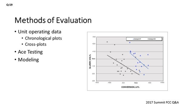
Using chronological plots by themselves is not an effective way to evaluate catalyst reformulation, so we have to introduce some other methods. Using cross-plots is one where you plot process variables. Instead of just against time, you plot them against another process variables. Further, you can use ACE (Advanced Cracking Evaluation) testing or pilot plant testing. Modeling can be used as well.
There are complications you will have to consider when you are planning for reformulation and the post-audit of it. Feedstock availability: Ideally, you would be able to run at least some period – both on your initial catalyst and your reformulated catalyst – using the same feed. That will eliminate a major variable in the evaluation. If you have shifts in economics that force you to change your operating mode, clearly you will have to consider that scenario, too. If you move from gasoline mode to trying to produce propylene to take advantage of that market, the post-audit will clearly be more difficult to extra out of the trial. On longer trials, you can run into summer or winter effects on blowers and compressors that will change your constraints; so, plan and account for such seasonal effects. There are logistical concerns with handling the catalyst, especially if you are reformulating from Vendor A to Vendor B. You might not use the same logistics company, so consider that as well. Lastly, putting in the wrong catalyst can be really expensive and will certainly complicate the catalyst trial. If you do not plan for and risk-mitigate it properly, you will end up cutting the trial short, which will be costly for you.
BHARGAVA (KBC Advanced Technologies, Inc.)
Catalyst change is one of my favorite topics, so it is appropriate that I answer this question. We have conducted catalyst evaluations for several clients; and not only have we been successful executing these base catalyst changes, but we have also found improvements for selecting the right catalysts for additives. We evaluated ZSM-5 additives from different vendors and have been successful differentiating ZSM-5 that comes with the base catalyst vendor with ZSM-5 coming from another catalyst vendor that just sells ZSM-5. We understand that small changes in the FCC yields are difficult to find, and these small changes – in themselves – equal millions of dollars of improvements you can do on a catalyst. One of the ways we bring value to the table is by putting in a very rigorous system of evaluating catalyst. As was just said, we also must do the preplanning, which I will talk about in my last bullet point. What we do is use simulation models. We installed a test run program to do a test run every two weeks during the catalyst transition, and we developed calibration factors.
What are calibration factors? These calibration factors are an indication of the mechanical efficiency of the unit. Given the mechanicals are the same, it helps you track the catalyst changes. So, the calibration factors are a proxy for what the catalyst is doing in the unit. Once you have the calibration factors, you can then make an apples-to-apples comparison. The feed changes in six months. While the catalyst is changing your operating conditions, constraints change. So, we make that comparison at constant constraints, and then we evaluate the results. We do sensitivities on different situations to determine which catalyst will work under which situations.
We benchmark. We find the cracking property on the catalyst to tell us what sort of changeout we have from the catalyst analysis. We do the analysis at 25% changeout, 50% changeout, and 75% changeout to validate the results when we do the analysis. Do not rely on the vendor estimates because they can be very different from what you actually see on the unit. You definitely want to employ an independent third-party company that either benchmarks or uses the pilot plant to give you yield estimates on your feedstock. It has to be done on your feedstock by an independent party to give you yield estimates at different cat oils at different ROTs (reactor operating temperature). Look for metal tolerance tests.
KBC has seven tests required to be done for each catalyst, if you are going to do the full catalyst evaluation. Once you get those results, you cannot use those results for any comparison on how good the catalyst will be, even at constant conversion, which is typically what the vendors or independent lab will give you. You need to change that data into a heat-balance model. These estimates have to be normalized so they will represent your unit. So, you need a base run calibration of your unit and then superimpose the catalyst effects on the base case calibration under heat-balance situations to get the right estimates you are seeking. Then, do a post-audit and compare it with the catalyst results.
DINKEL [Marathon Petroleum Corporation (MPC)]
I will echo that we like to look at multiple methods for confirmation; but within Marathon, we have our own circulating riser unit. That is where we heavily rely on looking at both the catalyst assessments for changeout, as well as the post-audit data. As Mike was saying, we are able to isolate variability from the commercial unit which allows us to focus on catalyst performance. We can look at the original feedstock at the end of the catalyst changeover, as well as the feedstock at the end of the run, which may be as much as six months down the road.
During the Annual Meeting in March, we co-presented a paper with Albemarle that detailed a catalyst changeout and got into more discussion on our uses of pilot plant. You can refer to the paper for more details, which was entitled “An Action Plan to Improve FCC Unit Performance at the Marathon Galveston Bay Refinery”.6
PHILLIP NICCUM (KP Engineering, LP)
I wholeheartedly agree with the suggestion to use a model to adjust the data. What I found and observed to be the most successful is that you can also do this leading up to the catalyst change. Take some routine tests, perhaps once a week. Get some good data, and then adjust it to some basis of a feed quality in operating conditions. Then, continue this process as you go into the trial. You will then have a way to isolate the feedstock quality changes and the operating condition changes that are inevitable and required in the operation. Using that data, you can then reflect on the effect of the catalyst. I am not a fan of using pilot plants to test it, because you cannot be certain of the testing protocol itself. The catalyst may be better in the pilot plant then it will be in your commercial unit. So, I believe in the benchmarking of the actual data and the collection of reliable data on routine basis, as well as watching the trial from the beginning. If it starts to go south, correct it before it gets bad.
BOB LUDOLPH [Shell Global Solutions (US) Inc.]
As part of the preplanning Mike outlined, do not forget the operability of the catalyst. For example, you may not get the opportunity to see the yield shifts if the catalyst circulation is challenged. So, go through the various unit operating parameters, identify where the unit operation could become constraining, and prevent your full realization of what the new catalyst has to offer. Try to put in some milestones early, while you are changing out, to check if you will be able to appreciate the projected yield structures. Just make that a part of your preplan.
MICHAEL FEDERSPIEL (W.R. Grace & Co.)
Preplanning is an important part of ensuring that the catalyst reformulation and post-audit are successful. Before the catalyst trial begins, it is important to define catalyst objectives and establish a clear evaluation plan on how these objectives will be monitored and evaluated for the trial. Sample and data collection guidelines and establishing a good base case should be done before the trial. It is critical that the samples and processed data needed to monitor the reformulation are routinely collected before and during the trial. It is also suggested to work closely with Operations, the refinery lab, and your catalyst supplier to guarantee that samples are being collected and the proper analyses are being performed.
After the process data and samples are collected and analyzed, there are several different methods – such as cross-plots, lab testing, and modeling – that can be applied to evaluate the benefits of a reformulation. The first method is the use of cross-plots. Cross-plots are an extremely useful tool to look at operating data and e-cat data on a similar basis. One example of a cross-plot is shown in Figure 1 where a refinery reformulated the catalyst to improve bottoms upgrading. At similar conversion, the refinery was able to achieve lower bottoms.
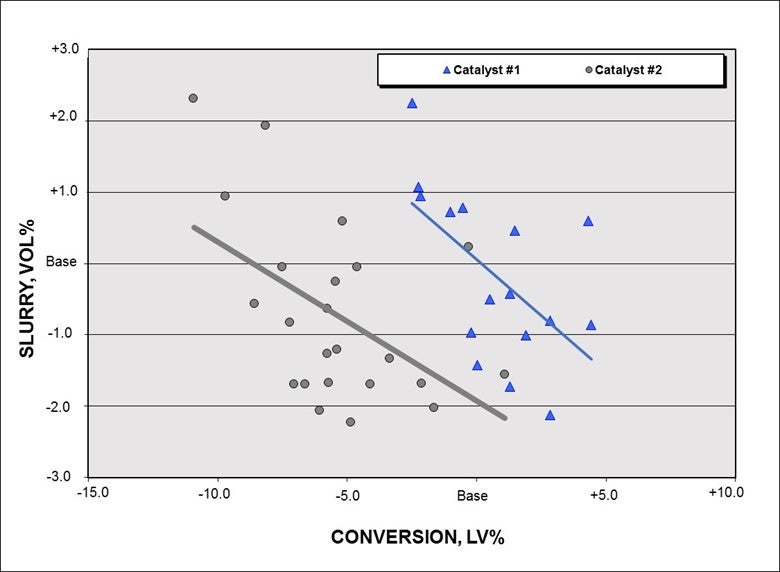
Figure 1. Slurry LV% (liquid volume percent) versus Conversion LV%
Other cross-plots, such as gas factor versus equivalent nickel or gasoline octane versus reactor temperature, could be useful to help determine the benefits of a catalyst reformulation. The catalyst objectives will determine which cross-plots are the most meaningful for the trial. When drawing conclusions on cross-plots, different operating conditions, feed quality, and catalyst health should be taken into consideration. This is why laboratory testing and models should be used in conjunction with cross-plots.
Laboratory testing can be used to help evaluate the catalyst reformulation. ACE testing and Grace’s DCR® (Davison Circulation Riser) testing can be conducted on the equilibrium catalyst to help determine the benefits of the reformulated catalyst. The advantage of lab testing is that it is conducted using fixed operating conditions and a fixed feedstock, thereby removing the uncertainty in results solely derived from unit operating data due to variability in these parameters over the course of the evaluation. Lab testing should be done with the refinery feed, base equilibrium catalyst, and reformulated equilibrium catalyst. The equilibrium catalyst should be chosen with similar metals levels which may not be possible during the trial if the unit experiences a shift in metals levels.
Another method to evaluate catalyst reformulation is the use of models. Models are tooled used to quantify catalyst reformulation benefits since they can be developed to predict yields shifts at defined conditions. When developing, calibrating, and using models, it is important to make sure that data input contains no errors. Before using a model to determine catalyst reformulation benefits, model-predicted yields should be compared to actual yields to validate the accuracy of the model. If the model cannot be validated, it should not be used in the evaluation.
Two model methods can be used to determine catalyst reformulation benefits. The first method is to calibrate and validate the model for the base catalyst. After the new catalyst is fully turned over, this model can predict what the yields would have been on the base catalyst at similar operating conditions. The predicted yields are then compared to actual yields to determine the benefit of the reformulation. The second method is a double-check of the first method. The model needs to be calibrated and validated for the reformulated catalyst. This model can then determine what the yields would have been on the new catalyst at base catalyst conditions. These predicted yields can be compared to the actual yields before the trial to determine the benefit. The results from both methods should be compared to make sure that the methods show similar benefits.
In conclusion, evaluating a catalyst reformulation can be very complicated since it is extremely rare for a unit to run in a stable manner with similar operating conditions, similar feed quality, and similar catalyst health. This variability in operation is why several methods need to be used to quantify the benefits of the catalyst reformulation.
SANJAY BHARGAVA (KBC Advanced Technologies)
Post-audits are very important to verify if the catalyst performed to its original estimates from the catalyst vendor and if it shows the same yield and property shifts as originally proposed. We prefer a very detailed post-audit consisting of high-quality, stable, and data-validated test runs (four to eight) performed on a weekly basis on the base catalyst followed by weekly test runs during the transition. A key catalyst parameter (such as rare-earth or alumina) is used to track the transition of the existing catalyst to the new catalyst. The unit performance (yields, properties, coke/gas selectivity, etc.) is also tracked and normalized using a simulation model and projecting several different simulations runs under constant conditions and constraints. This procedure is done with calibrated models at the base catalyst at 25% changeout, 50% changeout, and 75 to 80% changeout. Economics are applied to all the cases to determine the value of the catalyst change and then compared with the original delta estimates from the vendor. Next, the values are converted into heat-balanced yields, properties under constant conditions and current constraints to determine the success of the catalyst change.
This exercise is difficult since small changes are frequently expected which have a major economic benefit. So, there is a big incentive to have sophisticated tools and methodologies to perform stable test runs and do additional data validations.
BRYAN DINKEL [Marathon Petroleum Corporation (MPC)]
Best Practice for post-auditing catalyst changes on a unit includes using multiple types of reviews to provide assurance that all of the data is pointing in the same direction. We will use commercial data reviews, catalyst supplier assessments, and pilot plant testing – coupled with the utilization of a kinetic model – to translate pilot plant results to better reflect commercial unit results. In my experience, review of commercial data alone is often muddled with feed quality shifts; so typically, there are challenges getting clean baseline and post-changeout data sets for review. Catalyst supplier reviews will usually isolate catalyst performance based on their standard feeds and ACE (Advanced Catalyst Evaluation) run data, which is insightful but not as reflective as circulating riser unit (CRU) results. Within MPC, we utilize our internal circulating riser unit upfront in the catalyst selection phase and in the post-auditing period. The CRU allows us to isolate catalyst performance shifts and then plug that information into our kinetic model to optimize the unit against operating constraints. You can refer to the March 2017 AFPM Annual Meeting paper, co-written and presented by Albemarle and MPC, entitled “An Action Plan to Improve FCC Unit Performance at the Marathon Galveston Bay Refinery”7 for discussion in more detail.
REBECCA KUO (BASF Corporation)
In a perfect world, during a catalyst change there would be no feed or operational changes. However, this rarely occurs; therefore, the best way to post-audit a catalyst change is to track the equilibrium catalyst (e-cat) yields by ACE (Advanced Cracking Evaluation) testing, as the testing is done with a standard feed at constant operating conditions, so any deltas are attributed to the catalyst only. It is important to note, when comparing ACE yields reported by different catalyst suppliers, that the absolute yields will not be comparable as all suppliers use different feeds and operating conditions. The trends from baseline are the most crucial to track. Another option is to conduct lab testing (such as ACE or circulating riser unit) using the FCCU feed with both e-cats to post-audit the catalyst changes at apples-to-apples conditions. If using this option, make sure that important e-cat properties – such as Ni (nickel) and V (vanadium) – are similar between the two catalysts. If post-auditing the catalyst change with the operating data and reactor yields, a Best Practice is to use a kinetic model – such as FCC-SIM or a statistical model – to normalize the data for changes in operating variables and feed properties. Build a comprehensive and statistically-sound base case with the incumbent catalyst and project forward to the new catalyst. Any deviation from the model will be due to the catalyst change. Finally, when conducting a post-audit of a catalyst change, it is crucial to understand the turnover of the catalyst inventory. A rule of thumb is to start tracking the catalyst effects around 50% turnover; as at this time, about 75% of the activity will come from the new catalyst. At 75% turnover, about 90% of the activity will come from the new catalyst.