Question 58: What are your Best Practices for reliably measuring level in the bottom of the main fractionator?
FOOTE (CHS Inc.)
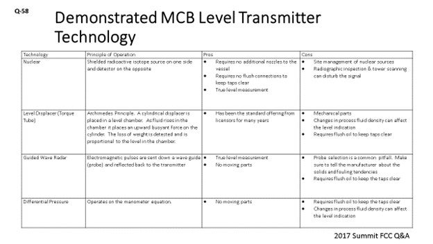
I prepared a few tables about technology and the principle of operation pros and cons of each of the demonstrated level of technologies and main column bottoms level transmitter. Again, it goes without saying that accurate measurement of the main column bottoms level is essential for reliability and safety. First, what I will talk about is nuclear. One of the benefits of nuclear technology is that it does not require any additional nozzles in the vessels. So, if you are looking for redundancy and do not want to go through the expense of installing a nozzle, this is a good option for you. Nuclear also does not require flush connections. Every bit of HCO (heavy cycle oil) flush you put back into the bottom circuit will affect your fractionation, so minimizing HCO flush is a big deal. Nuclear technology also gives you a true level measurement. The drawbacks to nuclear are obviously site management and nuclear sources; but likely, you already have these in your refineries. RT (radiographic testing) inspection and tower scanning can mess up your level indication. Just make sure people are communicating when they are doing x-rays in their work areas.
The next technology is the torque tube. Basically, it is a cylinder that operates inside of a chamber where the fluid exerts a buoyant force on the cylinder. The difference in the weight is detected and corresponds to a level. Torque tube technology has been the standard offering from licensors for years now. The drawbacks to it are that it is a little mechanical; not terribly mechanical, but there are pieces that can fail on it. It also changes in process. Fluid density on startup, shutdown, and malfunction can affect the level measurement. The torque tube also requires flush oil.
The third technology is guided-wave radar. Again, it gives you a true level measurement and has no moving parts. The common pitfall here is probe selection. Make sure your manufacturer knows that there is the potential for solids in these circuits and that he/she gives you the right type of probe. Sometimes the probes can be too tight, and you can plug them up. Guided-wave radar also requires flush oil to keep the taps operational.
The last technology is pressure differential, which is very similar to torque tube. It is a proven technology; but again, it does not give you a true level if you have gasoil, say, at the bottom of the main column on startup.
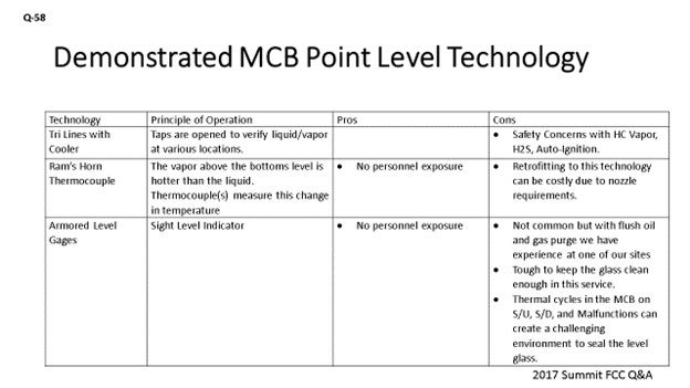
The next slide gives us the Point Level Technology. So, in addition to level transmitters, we also want to have point level indication. For years, the standard from licensors has been the try lines with the cooler. Obviously, the taps are open and you either have vapor or liquid there. The try line taps provide you with the means of telling you where the level is within the column. Obviously, there are safety concerns with try lines because you have H2S vapor and auto-ignition possibilities.
The second technology – Ram’s Horn Thermocouple – is one that I am not sure has been commercially demonstrated in an FCC unit but which I think has been used in crude and in vacuum columns. Basically, the sub-cooled liquid is detected as the level goes up. There is no personnel exposure here. Retrofitting this technology can be costly, because it does require one nozzle for the thermocouple and another one for the ram’s horn drain that goes down below.
Armored-level gauges have also been used. This equipment is not very commonly chosen. With purging, you can keep the glasses clean, although it is tough to do. Also, because of the thermal cycles you run on the startup, shutdown, or malfunction, keeping that glass sealed can be challenging. So, there are some challenges with that technology.
Regardless of the technology we are using, redundancy is important. Right? I think it is best to use two different types of technology, if possible. However, Best Practice is to employ two level transmitters with the selector switch from the main column bottoms level control. For displacers, guided-wave radar, dP transmitters, and redundant transmitters need their own individual taps. So, do not try to put them on one set of vessel taps, because that is a single point of failure. For point level measurement, at least two points should be measured for high and low levels.
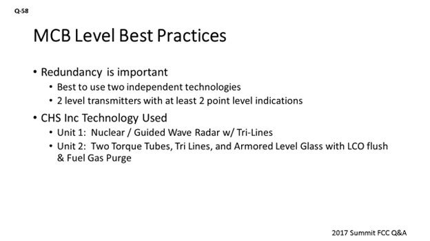
At CHS, we operate our Laurel, Montana FCC. We use nuclear and a guided-wave radar with flush oil, and we use try lines for point level indication. We are strongly considering going to the ram’s horn thermocouples because of safety concerns at that FCC. At our McPherson refinery, we use two redundant level displacers and two armored gauge glasses that have LCO flush and fuel gas flush or fuel gas purge as well. We also have tried lines at McPherson.
MALLER (TechnipFMC Process Technology)
The TechnipFMC standard is a diaphragm-type pressure differential level instrument. We use continuous HCO flushing. We would like to see multiple instruments there for redundancy. I would go as far as to say that three separate instruments should be used. That way, you have the chance that two of them read the same, rather than having to discern which is correct with only two different readings. Also, I like to see a local gauge for field verification, which I have seen successfully applied via magnetic-type float gauges in service.
TRAGESSER (KBR)
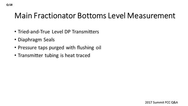
KBR’s normal practice is to offer a tried-and-true method that uses simple level transmitters for main fractionator bottoms. Both level transmitters are pressure differential types and share the nozzles at the vessel. Multiple transmitters are provided for improved reliability. The board operator has the option to switch between the two measurements.
Both level transmitters use a diaphragm seal to prevent slurry and solids from getting into the transmitter.
The main fractionator measurement nozzles at fractionator shell are purged. We use fuel gas to purge the low pressure tap and flushing oil to purge the high-pressure tap. The tubing for the transmitters is electric or steam-traced to minimize the potential for blockage if the purge is lost.
MELVIN LARSON (KBC Advanced Technologies, Inc.)
How far up do you take your top tap on your level transmitter?
MALLER (TechnipFMC Process Technology)
Typically, we have a reduced diameter boot at the bottom of the fractionator and we take the top tap at the top of that area. We do not take it up into the flash zone.
DARIN FOOTE (CHS Inc.)
The following tables list the demonstrated technologies to reliably measure main column bottoms (MCB) level. Regardless of the technology used, it is important to have redundant level indication. The Best Practice is to employ two level transmitters with a selector switch for MCB level control. For displacers, guided-wave radar, and dP level transmitters, redundant transmitters should be on independent vessel taps. There are benefits to having two different level technologies employed. For point level measurement, at least two points should be measured for high and low levels.
Table 1. Level Technologies for Main Column Bottoms Level Transmitters
|
TECHNOLOGY |
PRINCIPLE OF OPERATION |
PROS |
CONS |
|
Nuclear |
Shielded radioactive isotope source on one side and detector on the opposite |
|
|
|
Level Displacer (Torque Tube) |
Archimedes Principle: A cylindrical displacer is placed in a level chamber. As fluid rises in the chamber, it places an upward buoyant force on the cylinder. The loss of weight is detected and is proportional to the level in the chamber. |
|
|
|
Guided-Wave Radar |
Electromagnetic pulses are sent down a wave guide (probe) and reflected back to the transmitter. |
|
|
|
Pressure differential |
Operates on the manometer equation. |
|
|
Table 2. Demonstrated Methods for Point Level Indication in the Main Fractionator Bottoms
|
TECHNOLOGY |
PRINCIPLE OF OPERATION |
PROS |
CONS |
|
Try Lines with Cooler |
Taps are opened to verify liquid/vapor at various locations. |
|
|
|
Ram’s Horn Thermocouple |
The vapor above the bottoms level is hotter than the liquid. Thermocouple(s) measures this change in temperature. |
|
|
|
Armored Level Gages |
Sight Level Indicator |
|
|
At our Laurel, Montana FCC, we use nuclear and guided-wave radar for redundant indication and try lines for point indication. We are strongly considering getting rid of our try lines and replacing them with ram’s horn thermocouples due to safety concerns. In our McPherson, Kansas FCC, we use redundant level displacers and two armored gage glasses for point indication.
ALEX MALLER (TechnipFMC Process Technology)
We use diaphragm-type pressure differential level instruments with continuous HCO flushing oil provided to the connection at the vessel. Multiple instruments are typically used to provide redundancy and some confidence in the readings. A magnetic-type float gauge can also be provided for verification in the field, but it should be insulated, steam-traced, and provided with continuous flushing. With these arrangements, level measurement at the main fractionator bottoms is not typically a big issue. Some units have applied nuclear-type instruments successfully for this service, but it is not our standard to do so.