
Question 13: Severe fouling of diesel and gas oil hydrotreating preheat exchangers has been a growing problem. In your experience, what are the causes and how can these be prevented? Have you tried antifoulant injection in this service?
Dan Webb (Western Refining)
Fouling of the heat exchanger train is sometimes a problem particularly when processing cracked feed stocks. The fouling is often caused by polymer like compounds (gums) that form when petroleum distillates come in contact with air. When heated olefinic compounds react with absorbed oxygen to form gums that deposit in the preheat train.Iron scale and other particulates in the feed often adhere to these gums to produce severe fouling that restricts unit capacity and accelerates heat exchanger corrosion rates. Typically, every effort is made to avoid air ingress into any of the unit feed stocks. Fouling precursors may also be present in straight run feed stocks in the form of certain chemical contaminants that may be present in the crude or inadvertently introduced in an upstream process unit. Some precursors such as amines, carboxylic acids, and carbonyls form gums without air ingress into the feed. Antifoulants have been used successfully to mitigate fouling caused by these compounds in addition to mitigated fouling caused by oxygen contaminate cracked feed stocks.
Michael Chuba (Sunoco)
Typically distillate hydrotreaters exchanger fouling has been associated with cracked stocks that contain olefinic material and trace amounts of O2 coming in with the feed from tankage. In addition to oxygen-initiated polymerization, other impurities can lead to free radical formations that can promote polymerization reactions. These impurities include certain nitrogen and sulfur compounds well as some metal ions including iron, calcium, and magnesium.
In addition to free radial polymerization, condensation polymerization reactions can also result in fouling. In this route, two radicals can react to form a larger molecule. The new compound can continue to react and grow until it precipitates out of solution forming deposits.
What I would like to present here is an example of fouling we had on one of our units and how we have significantly reduce fouling via a simple jump over line.
Prior to conversion of this unit to ULSD the unit processed a mix of virgin and cracked distillate stocks. Historically this unit had exchanger fouling that was attributed to the presence of the cracked stocks. When the unit was converted to ULSD the cracked stocks were removed. The resulting feed was a 50:50 mix of direct rundown material from the crude unit and tankage. As a result of this change in operation it was anticipated that the fouling rate would decrease, however, during actual operation the fouling rate actually increased.
An initial program to address the problem included detailed analysis of the various feed stream followed by a targeted antifoulant chemical injection program. Results were somewhat effective but still left significant room for improvement. Continued investigation into the problem targeted O2 contamination coming from the material coming from tankage. The intermediate distillate tanks are cone roof design which would be relatively costly to convert to blanketed tanks. As a first step it was decided to install a jump over from the tank inlet line directly to the suction of the tanks’ transfer pumps. With this simple connection the average volume of material actually drawn from the tanks dropped dramatically.
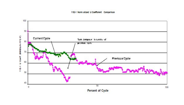
This plot shows the impact on the heat transfer coefficient of the feed effluent exchanger as a result of this simple jump-over. The pink plot represents the previous cycle. At about ¼ of the cycle the jumpover line was installed. At this point significant fouling had already occurred. The discontinuity in heat transfer coefficient a week or two later was the result of a power failure. It is suspected that the rapid depressurization dislodges some of the fouling material thereby improving the heat transfer when the unit is re-streamed. This same response has been seen in previous emergency shutdowns. The green plot represents the current cycle which started with a clean set of exchangers and operation of the jumpover in service from day 1 of the cycle. As can be seen this simple jumpover has significantly reduced the rate of fouling compared to previous cycles. Since the only change was the potential ingress of O2 from the tank, this project confirmed the impact O2 had fouling.
Gregg McAteer (Nalco Company)
Fouling can be a serious problem in hydro-desulfurization (HDS) units because of their importance in producing fuels that should meet environmental specifications. Fouling can limit a unit's ability to maintain a specific feed rate or meet an extended turnaround date. It can greatly influence product quality as well as energy consumption, and catalyst or equipment life. Stricter limits on sulfur and aromatic content of finished fuels make fouling control even more important today. To achieve today’s limits of 0.05 wt.% for diesel, refiners must increase severity of refining operations, which often worsen fouling. Fouling ultimately necessitates shutdown and extensive maintenance, a costly process, both in terms of maintenance expenditures and lost production. Causes of fouling in diesel and gas oil hydrotreaters are both organic and inorganic in nature. The organic foulants are primarily gums formed as a result of processing cracked material and accelerated if the material is exposed to oxygen at any time. Antioxidants and/or antipolymerants are used to reduce the formation of gums and dispersants are used to keep any gums already formed from growing in size.
In one case an antifoulant program utilizing both an antioxidant and a dispersant was applied to a gas oil hydrotreater that normally fouled enough to require a shut down after an average of 440 days. The antifoulant program started on a fouled system and showed
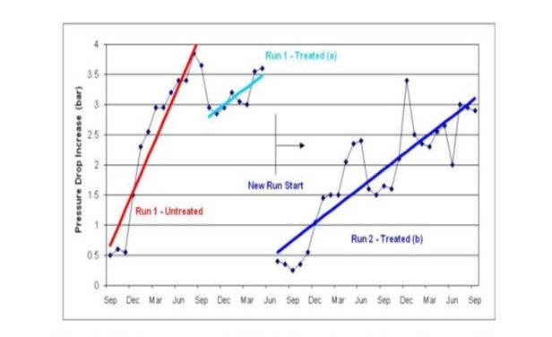
a slight recovery of pressure drop. After a shutdown they started again and achieved a 1300 day run (see graphic below).
“Run 1” is shown in red and light blue. The red trend shows the steep increase in pressure drop during normal operation (without antifoulant program). The light blue trend shows the antifoulant program started, saw a small decrease in pressure drop, and then the unit was brought down for a regeneration. “Run 2” is shown as the dark blue trend and shows a lower fouling rate and longer run length with the antifoulant program. Customer estimated the ROI to be between 400-500%.
Phil Thornthwaite (Nalco Company)
Foulants typically found on the feed side of the preheat exchangers include various gums or polymers, iron sulphide and salts.
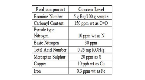
The organic fouling due to gums & polymers results from the polymerization of unstable species in the unit feed. The problematic species include olefins (generated in cracking processes), organic acids, mercaptans, ketones, aldehydes, phenols, organo-nitrogen and organo-sulphur compounds. Therefore, in order to determine the risk of organic fouling for a particular feed stream, detailed analysis for the problematic species can be useful guide in evaluating fouling propensity and mitigation strategies.
A typical level for concern for each problematic specie is outlined below:
Another key factor to consider is the oxygen content of the feed stream as this can promote the polymerization of various unstable compounds, particularly olefins. Therefore, it is good practice to exclude oxygen from feed storage tanks by ensuring tank seals and vents are in good condition and through the use of a nitrogen blanket. However, this method is ineffective with streams already exposed to oxygen since the nitrogen blanket will have no effect on oxygen reaction products such as aldehydes, peroxides and hydroperoxides.
Inorganic fouling is mainly caused as a result of iron sulphide that can either be carried from upstream units or generated in-situ in the preheat exchanger network. However, the latter is not so common since refiners choose the metallurgy to mitigate against sulphidic corrosion in most cases.
In order to mitigate and control fouling in the preheat train, chemical dispersants and antipolymerants are used. The properly selected dispersant will act upon the organic polymers by keeping them finely dispersed within the feed stream thus minimizing the risk of deposition on the exchanger surfaces. Likewise, dispersants can also prevent deposition of FeS by keeping them dispersed in the feed stream.
Antipolymerants act by disrupting the propagation and chain extending stages of the free radical polymerization reactions and by increasing the rate of termination. This will limit the rate of polymer growth within the preheat system. They will also minimize carbonyl formation which will in turn disrupt condensation polymerization reactions.
The key to monitoring the program effectiveness is through accurate monitoring of the preheat exchanger network. If the fouling results in a limitation of heat transfer efficiency, then a temperature survey of the exchanger network is carried out and this data is entered into a rigorous thermodynamic process model, such as Nalco’s MONITOR® program. This model will then use the plant data to calculate actual and normalized exchanger duties and heat transfer coefficients plus it will calculate the normalized furnace inlet temperature (NFIT). A successful antifoulant program will limit the decay in the NFIT and will generate significant returns for the refiner by improved energy efficiencies and optimized unit operation.
Robert Wade (ART)
We have not had success reducing fouling effects by adding antifoulants. It is our experience that adding antifoulants at best treats the symptom of the problem, and at worst further contributes to localized and downstream fouling. We recommend that the source of the fouling contaminant be identified through analysis and addressed at the source. If this is not possible then we revisit the basic design of the heat exchanger in question and ensure that it is operating in a shear controlled flow regime so that fouling effects are minimized
Year
2010
Process
Question 14: How do you ensure that the reactor effluent stream is evenly divided when going to parallel exchangers?
Michael Chuba (Sunoco)
Two phase reactor effluent flow to parallel exchanger trains need to be addressed during the design and initial piping layout phase. Once the system is installed very little can be done to evenly distribute the liquid and vapor. One can try to use valving to attempt to adjust the flow, but this typically results in a potential block-in case which could lead to the need of a high temperature relief valve on the reactor.
All of Sunoco units rely on symmetrical piping in units that have parallel exchanger trains with no major issues being noticed. If possible, the best design would have a straight horizontal run of 5 to 10 pipe diameters leading into the tee. Any elbow closer could lead to liquid preferentially accumulating on one side of the pipe entering the tee. This could result in uneven distribution of liquid in the tee.
As for liquid distribution, depending on degree of feed vaporization, a slight flow in- balance may or may not be that critical. In cases with a relatively high degree of feed vaporization a significant portion of the heat load is in condensing and not in sensible heat. In the case where 50% of the feed is vaporized, roughly 25% of the heat load is cooling the liquid. At 80% vaporization it drops to about 10% of the heat load. Thus, it becomes more of a vapor distribution problem.
For vapor distribution total downstream pressure drop up to the point where the streams are remixed becomes important. Thus, the corresponding exchangers in the parallel trains should be of identical design. If the exchanger train consists of multiple sets of stacked exchangers, it would be recommended that the flows be combined and re-split at the top of the succeeding set of exchangers.
On the feed side the liquid and vapor should be controlled evenly to the first exchanger of each train, if possible. This evenly controlled flow to each train should be kept separate throughout the entire preheat train.
Vern Mallett (UOP)
Splitting of reactor effluent material is accomplished via symmetrical piping from the common split to the common junction. In addition, the elbow upstream of the tee must be perpendicular to the run of the tee to avoid liquid favoring one branch over the other. Only one symmetrical split is allowed for reactor effluent material
Brian Moyse (Haldor Topsoe)
We have experience with two-phase flow using one reactor outlet feeding two feed effluent heat exchanger trains.
This is achieved using a long vertical pipe rise followed by a T-split. This is again followed by a completely symmetrical piping and equipment arrangement up to the mix point of the two trains and works well.
The vertical piping is supported by the platform which holds the feed/effluent heat exchangers. The flow regime in the vertical piping should be annular-mist flow.
Dave Ferguson (Tracero)
An online method for diagnosing the presence of this problem is to use a radioactive tracer test. Using external radiation detectors the velocity of the tracer material is measured (volumetric flow can then be calculated) in each branch of the piping. If the piping diameter is constant, then single detectors (using the area under each detector curve for flow comparison) can be used which is an advantage if the piping is short after the split.
Process
Question 15: ULSD reactor feed/effluent heat exchanger leaks can be a big problem meeting product specifications. What are best practices for detecting and preventing leaks? Are there new technologies or mechanical specifications to prevent cross contamination?
Michael Chuba (Sunoco)
With regard to feed/effluent exchanger leaks there are a number of actions that can be taken during the initial design phase of the unit. First, if feed/product exchangers are employed, the design should be such that the product side of the exchanger is higher pressure than the feed side. To accomplish this the exchanger would have to be located upstream of the unit’s high pressure charge pumps. If the unit has a feed surge drum this will require the drum to be designed for hot feed since it is recommended that the drum be located up-stream of the unit’s high pressure feed pumps in case of vaporization of the feed or water. It may also require relocating the product control valve downstream of this exchanger and designing the exchanger for a blocked-in pump discharge case. In any event the arrangement of having high pressure feed against low pressure product should be avoided.
As for the design of the feed/effluent exchangers where both sides are in the high-pressure loop, the driving force for leaks is much less and consists of just the reactor and exchanger delta P. When specifying the design of the tubes, they should be called out as being seal welded to the tube sheet. During turnarounds the tubes and seal welds should be inspected. Tube thickness can be checked using eddy current technique. Any tubes found thinning below acceptable levels should be plugged to ensure they don’t open up during the next cycle. In addition, seal weld integrity may be checked by performing a shell side hydrotest with the channel cover removed to look for wet seal welds. Liquid penetrant (PT) of seal welds is sometimes performed as well to look for seal weld cracks. Leaking seal welds are repaired by re-rolling, or by re-welding as a last resort.
As for identifying exchanger leaks, typical methods involve detecting the presence of a target molecule in the feed going into the exchanger and the product coming out of the exchanger. The target molecule can be an injected chemical, dye, or radioactive tracer or an indigenous molecular species that undergoes 100% conversion in the hydrotreater and can be easily detected.
As a first step we typically use sulfur speciation and track the easiest to convert sulfur species present in the greatest amount in the feed that gets completely converted at the operating conditions of the unit being run. The presence of this target molecule in the product from the exchanger (and its relative amount) would indicate a leak within the exchanger.
If a leak were indicated, our next step would be to identify the exact exchanger bundle/pass which is leaking. To date we have not had any leaks in any of our ULSD units.
Vern Mallett (UOP)
Hydroprocessing units employ a series of feed/effluent heat exchangers to recover heat from the reactor effluent and pre-heat the reactor feed. In these reactors, the reactor effluent is at lower pressure than the feed. As such, a tube leak will result in a partial bypass of feed material directly into the reactor effluent. When treating requirements are severe, small leaks will impact the product sulfur levels and potential adversely impact product yields and catalyst activity:
Methods that are currently used to determine if there is an exchanger leak.
1. Method A – Direct Sampling
2. Method B – Radioactive Tracers
3. Method C – Helium Tracers
4. Method D – Gasoline Dye Testing Method A – Direct Sampling
This method is based on measuring the sulfur content between the reactor outlet and the heat exchanger. If sulfur content upstream of the exchanger is higher than downstream, the most likely primary cause is a leaking exchanger. The sample line consists of small diameter, stainless tubing. During the sampling the operator should wear breathing apparatus because of H2S and hydrocarbon release. Samples should be taken at the following locations:
1. Between reactor outlet and first exchanger,
2. Directly after last exchanger, and
3. At the bottom of the stripper.
Method B – Radioactive Tracers.
Radioactive tracers can give excellent results in detecting leaking heat exchangers. The method is based on differences in residence time between feed passing and bypassing the reactor through the leaking exchanger. A disadvantage in using radioactive tracers is that it is done by specialized companies usually requiring permits. However, this method can give a reliable indication of a leak.
Method C – Helium Tracers
Similar to the radioactive tracer methods, helium is injected upstream of the suspect exchanger network. A helium detector is tied in downstream. Helium is spiked into the process. Based on time and concentration at the detector after the spike, the presence and magnitude of a leak is identified. The accuracy of this method has been consistently verified and is commercially available.
Method D- Gasoline Dye Testing
The gasoline dye test is effective on light-colored feeds such as naphtha, kerosene, or distillate. Sufficient dye is introduced into the feed such that enough dye passes through the leak to color the product. The dye is a nitrogen compound that will be rendered colorless when run through the catalyst bed. The reactor effluent is sampled before the suspect heat exchanger, if possible, and after the heat exchangers. If both samples are not colored by the dye, the heat exchanger is most likely tight. If the heat exchanger effluent is colored, the exchanger is leaking.
Dave DiCamillo (Criterion Catalysts & Technologies)
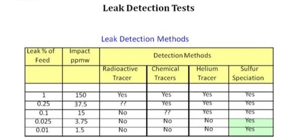
While there are several methods that can be used to detect feed/effluent heat exchanger leaks, sulfur speciation is the best method for detecting leaks in ULSD service. As the table below shows, only sulfur speciation has the precision to detect the potentially low levels of sulfur for suspected ULSD leaks. The basic approach is to use sulfur speciation to detect the most reactive sulfur species that normally would not be found in ULSD product.
While waiting for these analytical results, a quick field test would be to increase reactor temperature and measure the product sulfur response, if any. For example, increasing reactor temperature 10°F should result in a product sulfur decrease in the range of 5 to 10 ppm sulfur under normal operation. No response to successive temperature changes could be an indication of processing problems like a heat exchanger leak.
Dave Ferguson (Tracero)
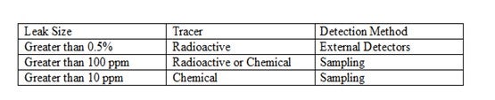
Online heat exchanger leak tests can be accomplished in a couple of different ways. One method involves the use of radioactive tracers. A very small volume of radiotracer is injected into the high-pressure side of the heat exchangers. Sensitive radiation detectors are placed on the low-pressure outlet of the exchangers. In an exchanger where a leak occurs the “leak” detector detects radiation on the low-pressure side, having leaked from the high-pressure side. This technique will find leaks greater than 0.5%. If samples can be collected, radioactive tracers can be used to find leaks as small as 100 ppm.
In many cases of ULSD exchangers very small leaks can cause a product to be off- specification. The leak size expected may be below the detection limits of the radiation detector. Tracerco has developed a family of chemical tracers which can be detected in hydrocarbon streams down to the ppb (part-per-billion) level. A small volume of chemical tracer is injected into the high-pressure stream to an exchanger. For this test the low-pressure side must be sampled. The samples are tested for the presence of the chemical compound and the exchanger was leaking if the test is positive. This technique can identify leaks as small as 10 ppm.
Meredith Lansdown (ART)
Even small leaks in the feed/effluent heat exchanger in ULSD units can cause problems with meeting product specifications and can shorten cycle lengths. Seal welding the exchanger tubes to the tube sheet in the design phase can help prevent leaks from developing in the first place. When the unit is online, several different methods exist for detecting leaks. Often times, the challenge lies not only in figuring out whether or not there is a leak, but actually locating it.
Sulfur speciation of feed and product is one of the more common methods for determining whether or not there is a leak. When carefully implemented, this method can be used to detect extremely small leaks in ULSD. Since the easily converted sulfur species are supposed to be removed in the hydrotreater, their presence in the product stream indicates that a leak in the feed line is allowing them to pass into the effluent. Sulfur speciation does not require sampling the reactor effluent or other samples points from which samples are not routinely taken; however, it also does not allow the refiner to pinpoint which exchanger is actually leaking.
Radioisotope tracers with external detectors mounted on the external lines of the exchangers can be used for feed leaks greater than 0.05-vol%. In this method, the isotope is injected upstream of the exchanger on the feed side, and the detectors measure the response time downstream. Having detectors on the effluent side of each exchanger is helpful in identifying which exchanger is leaking. Since sometimes a pickup of the tracer on the feed side of the exchanger can show up as a leak, in this method secondary leak detectors are often used as well. When using radioisotope tracers, it is important to ensure that the residence time is sufficient to notice the delay in picking up the signal. It is also important to sample the exchanger effluent lines in order to determine whether the leak is tracer pickup or an actual leak.
Feed leaks as low as 100-vol-ppm in the product can be detected using radioisotope tracers with effluent sampling instead of mounting external detectors. The tracer is injected into the feed inlet of one exchanger at a time and samples are obtained and analyzed onsite from the effluent side. The radiation counts from the exchanger effluents will indicate which exchanger is leaking.
Gas tracers, such as helium, are useful in determining whether or not there is a leak, but it may be difficult to quantify the leak size under 0.1-vol% because it may be difficult to obtain a representative sample.
TRACERCO has developed a group of chemical tracers that have even better limits than radioisotope tracers to find very small leaks, which do pose a threat to catalyst run lengthand product quality. These chemicals are selected to closely match process fluids. Since they are very stable, they flash in the presence of high temperatures in a hydrotreating reactor but then condense with the effluent without actually reacting themselves. They can be detected in the product at levels as low as 1-ppm, so theoretically, a leak as low as 1-ppm can be detected using this method. In using these chemicals as tracers, though, the samples must be sent to a laboratory for analysis. Also, this method does not indicate which exchanger is leaking
Process
Question 16: In your experience, are there documented cases of organic chlorides coming in with certain crudes? If so, what is their impact on hydrotreating units?
Brian Slemp (CITGO)
In researching this question with our corrosion experts, they identified this as a mature issue that has been well documented in NACE publications and international symposiums. These papers identify multiple cases of organic chlorides coming in with specific crude oils. Some of the documented cases indicate the presence of organic chlorides on an infrequent basis leading the author of one paper to refer to this problem as “Phantom chlorides”. (MV Veazey “Phantom chlorides real problems for refiners” materials performance vol 41 no 5 p 16 2002)
One of our refineries has encountered and identified organic chlorides in a specific crude. Our refinery reported the organic chlorides dropped the pH of the crude unit overhead system but did not impact our hydrotreating units. Another of our refineries has identified chlorides in the naphtha hydrotreating unit water wash system but has been unable to identify the source of the contamination.
The reported impact is similar to inorganic chlorides entering the hydrotreater from other sources such as HCL from the gasoline reformer. These are loss of heat transfer, increased pressure drop and increased corrosion.
Process
Question 17: What are the best practices to manage ammonium chloride fouling ? What methods are used to set wash intervals? What are the potential pitfalls?
Dan Webb (Western Refining)
It is not unusual that NH3, H2S, and HCl are all present in the reactor effluent stream. Since ammonium chloride (NH4Cl), and ammonium bisulfide (NH4HS) form above the dew point of water, water is injected in reactor effluent train, upstream of the effluent air cooler. Typical guidelines for designing and managing this water wash are as follows:
- At least condensate or boiler feed water quality should be used. Filtered stripped sour water may be used to supplement the wash water, but it is typically limited to no more than 50% of the total wash water rate. Furthermore, H2S, NH3, and dissolved solids may be present in the stripped sour water that could introduce detriments to the water wash performance.
- The wash water rate should be sufficient to ensure that at least 20% of the water remains in the liquid state. But, since ammonium bisulfide solutions are alsocorrosive to carbon steel, additional water may be required be injected to maintain an ultimate sour water NH4HS concentration of about 5 wt%. A lower design concentration may in fact be necessary as the process fluid velocity approaches about 20 ft/sec.
- Furthermore, corrosion is accelerated if the wash water contains ppm level oxygen or cyanide contaminates.
The injection point should be at a location that minimizes the risk of unsymmetrical flow. This typically necessitates separate injection points in the inlet to each back of the air cooler.
The water wash is engaged intermittently, at a frequency that is often determined through operating experience. A typical water wash frequency is twice a week for a duration of 2 hours.
Vern Mallett (UOP)
Ammonium Chloride (NH4Cl) salt deposition is a common problem encountered in hydroprocessing units. Salt deposition commonly occurs in the Reactor Product condenser (REAC), compressor inlet areas, and the overhead section of product stabilizers. Deposition will also occur in the Combined Feed Exchanger Train when the operating temperature of the exchanger decreases to the point where precipitation occurs.
Generlly there three sources of Chloride ingress into a hydroprocessing unit. Feed, hydrogen makeup gas, and wash water. Determining the source of the chloride and the amount is the first step in the program to control Ammonium Chloride salt precipitation.
Ammonium Chloride salts form because of the presence of ammonia and chlorides in the reactor effluent stream. These compounds combine and precipitate as the streams are cooled, and the effective concentration of the compounds increases in the gas phase. Depending on the concentration of chlorides and ammonia the salt will have different crystallization temperatures. At these temperatures the salt precipitation tends to occur along with salt deposition on exchanger tubes.
The following charts show the relationship between the concentration and the temperatures at which NH4Cl precipitation occurs.
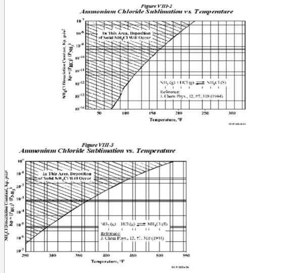
As seen from the charts, the deposition of these salts depends on the Kp values and the temperatures. The Kp values are obtained as follows
Kp(NH4Cl)= (PNH3)*(PHCl)
The charts also indicate that for the same Kp values, NH4Cl deposition occurs at a higher temperature as compared to NH4HS. The way to overcome this salt deposition is to inject wash water in order to dissolve the salts. As per UOP practice, the normal point of injection of the wash water is upstream of the REAC (Reactor Effluent Air Cooler). The temperatures experienced at the REAC are the area most prone to NH4HS salt deposition.
However as seen from the chart, NH4Cl has a higher sublimation temperature than NH4HS. These temperatures are often experienced at the Combined Feed Exchanger upstream of the REAC; hence there exists a possibility for salt deposition mainly NH4Cl at this region. In order to remove NH4Cl foulant, UOP has a water injection connection upstream of this CFE as well.
UOP normally suggests that wash water be injected periodically depending on the performance of the exchanger. But it is also not desired that water be injected continuously as it affects feed/effluent heat recovery and also can remove wash water from the normal injection point upstream of the REAC.
The points of injection of wash water should include those areas in the reactor loop where there is a possibility of crystallization of NH4HS or NH4Cl. The crystallization of these salts occurs at a particular Kp value dependent on the concentration of the salts as well as the temperature. The three primary aspects of wash water injection include
- The injection rate should be between 5-10% of fresh feed rate
- The maximum allowable concentration of NH4HS in the water after washing is 8%
- It should be ensured that at least 20% of the water remains in the liquid state after injection and does not flash.
The greatest effects of these salts occur due to their deposition in the tubes of exchangers resulting in very high velocities of flow and hence high levels of corrosion.
There are several other practices to minimize the possibility of NH4Cl salt deposition on the tubes. These include:
a. The nitrogen level in the feed and sulfur
b. The chloride level in the feed
c. The wash water quality
d. The sour water from the Cold Separator which has ammonium salts, H2S, NH3, Fe, and Cl.
UOP normally specifies the quality of wash water in the General Operating Manual (GOM) which is supplied to the customer. Regarding water quality the present water quality specification allowed is:
Total dissolved solids (TDC): 25 ppm (max) Dissolved oxygen: 0.05 ppm (max)
pH: 7 to 9
Chlorides (Cl-): 5 ppm (max)
NH3: 100 ppm (max)
H2S: 100 ppm (max)
UOP wash water injection practice allows up to 50% stripper sour water use from a dedicated sour water stripper. This is to guard against contaminants that could be in water from other units.
UOP’s stripped sour water quality should meet the following specification. TDS: less than 50 ppm
O2: less than 50 ppb
pH: 7 to 9
Cl-: less than 5 ppm NH3: less than 100 ppm H2S: less than 100 ppm
Since different crudes have different levels of sulphur, nitrogen and chlorides, it is impossible to have a single set regime for wash water as the appropriate point to inject water since it is also feed and operating condition dependent. If NH4Cl fouling is being observed, a regular regiment of periodic wash water will help to maintain heat exchanger efficiency. The frequency of wash water is determined on a case-by-case basis. However, removing the source of chloride in the feed or makeup gas is the best solution to avoid NH4Cl fouling in CFE.
Gregg McAteer (Nalco Company)
There are absolutely documented cases of organic chlorides coming in with certain crudes. Any chlorides that make it to a hydrotreater can react with ammonia to form ammonium chloride in the effluent stream and foul the exchangers. The salt is also corrosive, so the exchangers would foul and corrode at the same time. One location had the exchangers designed so they could bypass each exchanger in order to perform maintenance on failed exchanger tubes. The problem normally occurred in the 5th and 6th exchangers. They started up a water wash between the second and third exchanger and added a salt dispersant. The water wash has to be designed to reach dew point plus at least 25% in order to be effective. The salt dispersant will help keep the salts from building up on the tube surfaces. Together the water wash and the salt dispersant provided a long run (tripled the time between needing maintenance on the exchanger tubes).
David Krenzke (ART)
From our experience crudes do not naturally contain organic chlorides compounds. However, in some cases they become contaminated with organic chlorides from production additives or some in-refinery sources. Small amounts of chloride do not have a negative effect on hydrotreating catalyst performance. Initially the chloride will react with the alumina support to form aluminum chloride. This will then interact with trace amounts of water vapor in the gas phase to form hydrogen chloride which in turn reacts with the alumina support further downstream eventually reaching an equilibrium which will limit the concentration of chloride on the catalyst. The presence of HCl in off gas may, however present corrosion problems for downstream equipment.
Phil Thornthwaite (Nalco Company)
Earlier this decade, a number of European refiners received cargos of Urals crude (aka Russian Export Blend) that had high levels of organic chlorides. Experience in processing this crude suggested that this contamination was seasonal, and these particular cargos were received in early spring. It has been suggested that the levels of organic chlorides could be the result of them being used either in the crude production system to reduce wax deposition after the winter period or in the shipment process, where chlorinated solvents may be used to clean out systems, ship holding tanks, etc. Furthermore, crude quality varied significantly depending on the point of origin.
Other crudes have shown intermittent high levels of overhead chlorides and it has been suggested that this is a result of acid stimulation techniques used in the oilfield. These employ the use of hydrochloric acid to dissolve accumulated scales in the well thus improving the flow of oil. Under well temperatures and pressures, it is hypothesized that asphaltene hydrochlorides are formed and it is these that thermally decompose giving rise to elevated levels of chlorides. However, this form of organic chlorides presents the greatest risk to atmospheric and vacuum units and in some cases downstream conversion units such as visbreakers, cokers and RFCC’s.
The greatest risk to hydrotreating units is posed by organic chlorides is by the contamination of crude with chlorinated solvents. The portion of these solvents that do not thermally decompose can find their way into the lighter distillates such as the naphtha and kerosene fractions. When these streams are processed on a hydrotreater, they decompose to liberate hydrochloric acid and in the effluent stream of the reactor, they react with ammonia to form ammonium hydrochloride salts in large quantities. The generation of these large volumes of salt can lead to fouling of the feed effluent exchangers and downstream trim coolers that can in turn result in throughput limitations. Additionally, these salts can foul safeguarding equipment such as pressure relief and flow control valves and instances of salt related fouling could compromise process safety.
Another concern is the high rates of corrosion that can be observed due to these salts. The ammonium chloride salts are extremely hygroscopic and readily absorb water, even before the water dew point. Once water has been absorbed, a localized corrosion cell is formed that can lead to high rates of pitting corrosion leading to failures in the affected exchangers.
Gregg McAteer (Nalco Company)
A continuous water wash designed to reach dew point plus at least 25% is the minimum best practice. If monitoring or experience shows the problem to persist, then the addition of a salt dispersant is the next step. The question asks about water wash intervals, which implies that a non-continuous water wash would be a best practice – it is not. Many uses intermittent water wash, but this is not best practice. An intermittent water wash will cycle the exchanger surfaces from wet to dry to wet, etc. Ammonium chloride is hygroscopic, so water will be absorbed into the salt and hydrochloric acid will form between the salt and the exchanger tube causing pitting corrosion. The answer to question 17 gave an example of a water wash and salt dispersant used to give the refiner a long run on the hydrotreater.
Paul Fearnside (Nalco Company)
One of the downsides to using water washes within distillation towers is how the FeS scale is moved each time. After a few water washes the downcomer sections can become plugged with this scale. Better way is to utilize a salt dispersant such as that supplied by Nalco, without water, to keep these salts moving. This also alleviates the need to “slump “the tower for the water wash and does not reduce the tower throughput. These treatments can be intermittent or continuous depending on the severity of the salt fouling.
Phil Thornthwaite (Nalco Company)
The most common means for mitigating ammonium chloride salt deposition is with the installation of a properly designed wash water system. In order to provide effective wash water, the following aspects have to be carefully considered:
- Wash water source – the water should be of good quality and the primary contaminants to avoid are oxygen, hardness and high levels of filterable solids.
- Wash water injection rate – The wash water should be injected on a continuous basis and sufficient water must be added to the system to ensure that condensed water droplets are present and that the vapor is saturated (i.e., forcing the thermodynamic aqueous dew point). An excess is injected, typically 25%, is injected to ensure the vapor stream is saturated. The correct volume of water can be calculated from phase modeling.
- Injection location - key factor to consider is the layout of the heat exchanger network, as this will affect the distribution of flow and is likely to impact on the effectiveness of the wash water injection. Many overhead systems consist of multiple banks of exchangers in series and parallel, many of which are asymmetric in their layout. The liquid flow path in most cases is considerably different to that of the vapor and impacts the efficiency of the wash water injection.
- Equipment requirements - The method of injecting the water should be such that the vapor / liquid contact is maximized and that the water is distributed to all parts of the system. In order to ensure good distribution, spray nozzles are used (e.g., Spraying Systems Whirljet nozzle) in order to provide a full cone spray pattern with a small droplet size. Orientation of the nozzles must be co-current with the flow. Also, there should be the means to determine the water flow rate in order to provide evidence of flow.
When designing the wash water injection, the velocities of the system need to be considered. If the velocity is too high, there can be accelerated corrosion rates caused by water droplets impinging on equipment surfaces. Therefore, the location of the wash water injection is of critical importance, and it is common industry practice to locate the injection nozzle 10 pipe diameters upstream of any bends or elbows. However, it is prudent to routinely monitor immediately downstream of the injection nozzle and on the outer radius of the first elbow after the wash water injection.
The reliability and effectiveness of a wash water system can easily be compromised, even if properly designed. The following outlines some commonly found problems encountered:
-
Periodic Loss of Flow
-
Typically caused by solids plugging nozzles, valves and flow meters.
-
Insufficient Wash Water Rate
-
Unit conditions have changed since the system was designed
-
Partial plugging of nozzles, filters, valves & lines.
-
System operated intermittently rather than continuously
-
Poor Distribution of Water in the System
-
Incorrectly sized nozzles or no nozzles used at all
-
Incorrect orientation of nozzles
-
Incorrect location of nozzles
-
Low system velocities
-
Increased Corrosion Rates Observed
-
System velocities are high
-
Poor quality water sources (e.g. oxygen ingress)
Year
2010
Process
Question 18: What are your key strategies to maximize the heavy diesel barrels in the diesel pool without cracking? Do you consider blending and dewaxing etc. to meet product specifications?
Vern Mallett (UOP)
Generally maximizing heavy diesel barrels in the total refinery diesel pool would be based on distillation cut points the diesel processing units, mainly crude atmospheric columns. The objective is to maximize barrels by increasing distillation cut points up to distillation cut point maximum or to product quality specifications. Most likely the diesel derived from distillation will need to be further hydrotreated to sulfur specifications. Cetane requirements for finished diesel products will also need to be taken into consideration when blending straight run diesel. There may also be regulations and constraints on other product qualities such as olefin content, or aromatics for example which will need to be taken into consideration when maximizing total diesel refinery pool
Blending is commonly considered and used to increase the overall distillate blend pool for refiners. Hydrotreated diesel and or distillate are used to blend lesser quality diesel. This is evident in cetane barrels upgrading where high-quality hydro processed diesel range products are blended with lower cetane product to upgrade the overall diesel pool cetane value.
Heavying up the distillate end point may introduce cold flow property problems. This is especially common with virgin and paraffinic feedstock sources. Depending on local specifications for cloud point, pour point or cold filter plugging point it may not be possible to year-round end point extension to increase distillate yield. There are 3 main ways to mitigate cold flow problems: blending in lighter components (typically kerosene), using cold flow improving additives and catalytic dewaxing.
Kerosene blending is an effective remedy if available. The margin differential to jet must be considered to determine if the blending is economically viable. Cold flow improvers can be quite effective, especially for relatively small improvements in properties. These additives can be costly so large improvements in cold flow properties using additives may be cost prohibitive. Catalytic dewaxing for distillate fuel production is usually accomplished fixed bed hydrocracking catalyst utilizing shape selective zeolites. Cold flow properties are improved by selectively cracking paraffins, with selectivity to naphtha. Distillate yield loss is normally proportional to the degree of cloud point reduction. Yield loss could be minimized using dewaxing plus Isomerization, but the noble metal Isomerization process is very seldom economically justified for fuels production.
Dewaxing catalyst can usually be incorporated into the same reactor as used for distillate hydrotreating. Raising temperature in the dewaxing catalyst bed controls the amount of cracking and thus cloud point reduction. Since the cracking temperature is typically higher than required for desulfurization, the dewaxing function can be reduced in the summer when cold flow specifications may be less severe, thus increasing distillate yield. Obviously there will be some reduction in distillate hydrotreater cycle life because of the reduced hydrotreating catalyst volume in the reactor as well as the higher operating temperature required to achieve dewaxing. The UOP-Albemarle Hydroprocessing Alliance offers catalysts and processes for catalytic dewaxing.
Brian Slemp (CITGO)
Choosing the proper crude slate is the best starting point for ultimate maximization of the refinery’s diesel product capabilities. The proper crude slate will allow the refinery to hit multiple constraints and process unit limits. The newer higher activity desulfurizing catalysts and customized reactor loading philosophies have presented the refiners with the opportunity to dig deeper into the light cycle oil and light coker gas oils and help increase overall diesel production. Depending on the refinery configuration, hydrogen availability, and ULSD unit operating conditions the addition of a hydrocracking catalyst layer in the ULSD reactor is being considered as a means to increase the recovery of incremental diesel material from FCC feed pool and FCC bottoms product.
Year
2010
Process

Question 19: In your experience, what are the effects on ULSD hydrotreaters when FCC operation is adjusted to maximize diesel?
Praveen Gunaseelan (Vantage Point Energy Consulting)
There are a number of approaches to maximize the diesel yield from FCC units, such as catalyst optimization, process modifications, and changing the FCC product cut points. These approaches can be used independently or in combination - the ultimate objective being to maximize the production of light-cycle oil (LCO) from the FCC unit for subsequent conversion to diesel.
Increasing the LCO content in the feed to ULSD hydrotreaters can significantly impact their operation. FCC LCO is generally of heavier gravity and higher in polyaromatic content and requires more severe hydrotreating than conventional ULSD feedstock such as straight run diesel. As a consequence, ULSD units that process increasing amounts of LCO may require higher operating temperatures – potentially reducing ULSD catalyst life – and consume larger amounts of hydrogen than conventional ULSD feedstock. FCC LCO also has the effect of lowering the ULSD product cetane number, and thus the fraction of LCO in the ULSD feedstock may have to be limited to conform to product cetane specifications.
Some of the adverse impacts of processing LCO in ULSD units can be mitigated by reducing the LCO gravity and polyaromatic content in the FCC unit. This can be accomplished by a number of approaches such as using tailored FCC catalyst formulations, increasing the severity of FCC feed pre-treatment, and appropriately lowering the LCO endpoint.
Dan Webb (Western Refining)
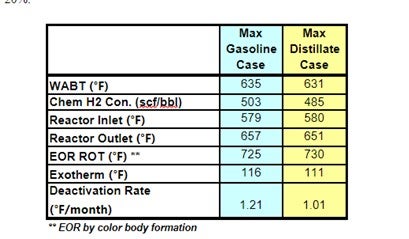
LCO becomes easier to treat when the FCC is adjusted to maximize refinery diesel production as Main column cut point changes are made to drop the back end of LCN into LCO. Not only does the LCO fraction become lighter, it also contains a higher fraction of less refractive (sterically hindered) sulfur compounds. The table below shows actual feed blend stock component analysis shifts in FCC max gasoline and max distillate modes.
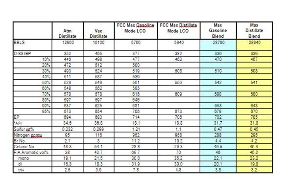
Haldor Topsoe used these actual component analyses to project DHTU catalysts performance. The following unit operating conditions were assumed to be constant.
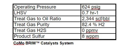
The projections below show that operating the FCC in max distillate mode produces a less severe DHTU feed stock: WABT is reduced by 3 -5 °F; 5-10% less H2 consumption; and catalysts deactivation may be reduced by as much as 20%.
Larry Kraus (Criterion Catalysts & Technologies)
Adding heavy diesel barrels to the feed to a ULSD unit will make the feed more difficult to process in terms of sulfur removal. Heavy feed barrels will also make it more difficult to ULSD products to meet T90 distillation specifications as defined in ASTM D-975. Mild conversion (mild hydrocracking) is sometimes employed in ULSD units to meet distillation specifications. If cracking cannot be utilized due to hardware limitations for naphtha handling or naphtha economics are not favorable, then aromatics saturation is the primary means to shift distillation The number of heavy barrels that can be added to the feed is then constrained by the ability of the unit to meet distillation specifications via aromatics saturation, and possibly cold flow properties. The combination of deeper aromatic saturation combined with heavier feeds containing longer paraffins both exacerbate diesel cloud and pour point, in many circumstances requiring further adjustment.
There are several routes to improve the cold flow properties of distillates. The addition of kerosene and / or cold flow improvers to the diesel pool is the most widely applied routes. Chemicals are effective for pour point and CFPP improvement but have little effect on cloud point.
The amount of kerosene blending is flash point constrained. Light material blending can have a negative effect on some product properties such as cetane and sulfur (if using untreated kerosene). The loss of kerosene in the diesel or heating oil pools is typically not an economically attractive option.
Another approach is to install a catalytic dewaxing unit to selectively reduce the cold flow properties of selected refinery streams or to revamp an existing ULSD unit to accommodate a bed of a dewaxing catalyst. In most commercial applications, catalytic dewaxing of diesel is carried out in single-stage, series flow configuration where desulfurization is carried out prior to dewaxing. Such processes involve base metal dewaxing catalysts usually in sandwich configuration below HDS catalysts, with the dewaxing catalyst being used under severe conditions (i.e., in the presence of H2S, NH3, unconverted organic nitrogen and sulfur-containing molecules). Alternatively, a two-stage configuration employing a noble-metal, second-stage catalyst can be used to provide isomerization / cracking dewaxing. Typically, two-stage dewaxing provides significantly higher yields of higher quality products.
Criterion Catalyst & Technologies and Shell Global Solutions have been involved in numerous projects over the last decade to revamp or build dewaxing capability in refineries that need mild to severe cold flow improvement in their diesel pool.
Sal Torrisi (Criterion)
In maximizing LCO from the FCC, this typically means increasing primarily the LCO and also the HCN volume. We observe that these streams get less aromatic and have a higher API, in many circumstances due to a decrease in conversion or cracking intensity. The combined changes in volume and quality of LCO and HCN can have measurable impact on operation of the ULSD unit as described below:
- Desulfurization Performance – In general, the percentage of difficult sulfur species in LCO as well as the nitrogen content goes down as the volume is increased. If the LCO volume in the ULSD unit remains constant, then the feed blend can be easier to process, however it is a more likely scenario that the extra LCO is processed in the ULSD unit. The net performance of a higher volume of slightly easier to process LCO usually means higher temperature requirements, higher deactivation rate and shorter HDS catalyst life.
- Hydrogen Consumption – More, but less aromatic LCO, will still result in an overall increase in hydrogen demand for the refinery. If the LCO is to be upgraded into diesel, it will need anywhere between 600-1600 SCF/B of hydrogen depending on the operating severity of the ULSD unit. For newer, high pressure ULSD units having ample makeup and recycle hydrogen, this is usually a minor issue. For moderate pressure units, the extra volume of LCO may be a challenge to handle both from a hydrogen supply standpoint as well as from an operation standpoint. See deactivation comment.
- Catalyst Deactivation – Two of the variables that correlate strongly with catalyst deactivation are the quantity of polyaromatics passed across the catalyst and the hydrogen partial pressure. As the LCO rate goes up, so will the polyaromatic coke precursors. In addition, as the hydrogen consumption increases, the subsequent hydrogen partial pressure throughout the system will decrease. The combined effect of these changes can be a measurable increase in catalyst deactivation rate.
- Product Quality – With less aromatic LCO, the cetane of this component will increase. However, the increased quantity of LCO will typically overwhelm this higher LCO cetane to cause a lower overall ULSD unit feed cetane number. If the refinery diesel pool is not cetane constrained, then this is not an issue, but many refiners are pushing cetane limits today and even require additives to make specifications.
If the increased volume of LCO pushes the ULSD operation into a unit constraint, there are ULSD catalyst options available to manage cycle length, hydrogen consumption and even product quality, enabling refiners to maximize diesel volume by incorporating more of these challenging FCC products into the diesel pool.
Brian Watkins (ART)
Increasing the quantity of heavier boiling fractions (LCO, Coker, Light Gas Oils) to the diesel hydrotreater has a number of impacts both on the performance of the hydrotreater and on the resulting ULSD product properties. Higher boiling fractions typically increase the amount of hard sulphur compounds, as well as increasing the amount of nitrogen and complex aromatic species. This has the combined effect of lowering the product cetane and limiting end of run (EOR) by making it difficult to maintain diesel ASTM color. Since general hydrotreating reactions do little to shift distillation, only a small quantity of higher boiling materials can be placed into the pool to maintain the product distillation specifications.
With the use of a selective ring opening (SRO) catalyst as part of the catalyst charge ART is able to improve diesel product cetane numbers by reducing total aromatic and PNA levels. The addition of SRO catalyst also helps provide additional EOR life in terms of product color. A catalyst system utilizing a high activity NiMo (NDXi) coupled with a selective ring opening catalyst will provide the same HDS and HDN activity, while having the ability to process additional LCO and other higher boiling fractions as well as achieving higher aromatic saturation conversion compared to the hydrotreating catalyst alone.
The new SmART Catalyst System® with SRO catalyst capability is very effective for reducing aromatic rings found in heavier feedstocks providing improved cetane and color performance. The majority of this increase in traditional cetane upgrading is due to the saturation of poly aromatic compounds with some moderate amount of mono aromatic saturation. Saturating aromatic rings is an effective way to improve cetane, but there is a practical limit to the amount of cetane uplift that can be achieved. The reaction becomes thermodynamically limited near the end of the cycle resulting in a much lower level of cetane uplift and possible color problems. A better approach is aromatic saturation followed by selective ring opening. The resulting product has a higher cetane and lower aromatic and boiling point and avoids the issue of thermodynamic control at the end of the run. Additional information on this process can be found in the NPRA paper AM10- 166.
Advanced Refining Technologies (ART) is well positioned to provide assistance on how best to maximize unit performance and to take advantage of opportunities to successfully process more complex feeds into the ULSD pool. ART has developed catalysts specifically designed to handle more difficult feeds exemplified by the SmART technology for ULSD. The technology has been widely accepted and the addition of an SRO catalyst to the ULSD catalyst portfolio provides refiners with greater flexibility in the operation of their diesel hydrotreating units.
- Product Quality – With less aromatic LCO, the cetane of this component will increase. However, the increased quantity of LCO will typically overwhelm this higher LCO cetane to cause a lower overall ULSD unit feed cetane number. If the refinery diesel pool is not cetane constrained, then this is not an issue, but many refiners are pushing cetane limits today and even require additives to make specifications.
Year
2010
Submitter
Process
Question 20: How do refiners quantify the impact of sodium on hydroprocessing units, specifically those processing either residuum or VGO feeds?
Dan Webb (Western Refining)
Sodium generally enters a hydrotreater due to upstream addition of caustic soda or desalter operational problems. Feed sodium content of more than 3-5 ppm should be avoided. Sodium has a significant deactivation effect; 1-3 %wt results in a 50% loss of catalyst activity. The deactivation mechanism is by blocking of acid sites and a reduction in the cracking function. Also, sodium penetrates the entire pore structure of the catalyst; and, when combined with water, can weaken the catalysts support structure causing breakage and high pressure drop. Sodium promotes catalysts sintering during regeneration. Catalysts containing more than 0.25 %wt sodium are not suitable for regeneration.
Brian Slemp (CITGO)
Prior to VGO reactor loading, CITGO projects the level of feed containments and we work with the catalyst vendors to customize the reactor catalyst system metals trapping capacity to achieve the desired run length with maximum value creation. We monitor our feed sodium along with other feed contaminants and estimate the projected level of metals trap saturation. Post reactor dumping, we validate the saturation projection via spent catalyst testing and modify the next catalyst system based on the spent catalyst contaminants level and the anticipated future feeds. As a side note, our historical observations show the feed testing indicates a higher level of sodium contamination than the spent catalyst testing validation. We also monitor our reactor products for indication of metals trap breakthrough such as increased light ends production and loss of volume swell as compared to design.
Vern Mallett (UOP)
Sodium usually enters a hydrotreater as a contaminant from improper desalter unit operation and/or caustic addition in the crude tower to neutralize high TAN feed stocks. Sodium adversely impacts the performance of all hydrotreaters so removing it from the feeds to the hydrotreater is the best solution. Nonetheless, upsets or specific crude runs may introduce enough sodium to VGO or residue hydrotreaters to cause a reduction in performance. Sodium predominantly affects HDS, HDN and HDA reactions. HDM and HDCCR are less affected. Thus, preventing sodium migration from the top bed and guard catalyst to the main active catalyst is important to maintain unit performance as long as possible.
In fixed bed units, Na can deposit both on the catalyst particle surface and within the catalyst pore structure of VGO and residuum hydrotreating catalysts. When depositing on the surface and interstices, the result is likely to be pressure drop build-up while deposition inside the particle generally results in reduced activity. Spent catalyst may accumulate 10 wt% or more of Na when deposited internally, depending on catalyst type and structure. Na is generally observed as Na2S crystals and in combination with Fe as FeNaS crystals. 1 wt% of Na deposited within the catalyst reduces activity by 10-20% and 5 wt% Na on catalyst results in 40-50% activity reduction.
Catalysts with high Na are unsuitable for regeneration since the heat treatment required to remove coke deposits allows the Na on spent catalyst to react with the alumina support. Surface area is drastically reduced during regeneration of high Na containing spent catalyst resulting in very low activity recovery.
Kevin Carlson (Criterion Catalysts & Technologies)
The refining and catalyst industry generally consider sodium to be an adverse feed contaminant resulting in catalyst fouling and deactivation. Criterion as well as other major catalyst developers continues to advise their client base to be aware of the potential impacts. Na can naturally come from crude oil or can be present in aqueous emulsion with the oil. Sodium affects catalyst activity within the cycle in which it is deposited as well as limiting the regeneration of Na contaminated catalyst for reuse. Presence of 1% Na2O on spent catalyst has been shown to reduce activity by more than 50%. It is recommended that efficient operation of desalting units is maintained, and regeneration is not recommended for spent catalysts containing more than 0.25% of sodium.
Data available on catalyst activity affected by deposition of sodium within the same cycle in which it was deposited is rather limited, making “quantification” of the impact difficult. In most of cases Na is carried into hydroprocessing units by aqueous emulsion with the feed. Sodium tends to deposit in the upper portion of the catalyst bed that can result in a crust that increases pressure drop and adversely impacts reactor flow distribution.
Greg Rosinski (ART)
Sodium (Na) is a severe catalyst poison that can cause significant activity loss even at low levels. It works by promoting the sintering of catalytic metals and neutralizing acid sites. Typical sources of sodium include a malfunctioning de-salter, sea water contamination or caustic contamination. Depending on the source of sodium, the signs of poisoning include rapid activity loss and an increase in pressure drop. The figure below shows the impact of sodium poisoning on catalyst activity.
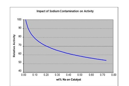
The figure indicates that for a sodium content of 0.5 wt% the activity is at most 60% of fresh catalyst activity. This translates to roughly 30°F loss in activity for 1 wt% sodium on the catalyst
Year
2010
Process