Question 17: What are the best practices to manage ammonium chloride fouling ? What methods are used to set wash intervals? What are the potential pitfalls?
Dan Webb (Western Refining)
It is not unusual that NH3, H2S, and HCl are all present in the reactor effluent stream. Since ammonium chloride (NH4Cl), and ammonium bisulfide (NH4HS) form above the dew point of water, water is injected in reactor effluent train, upstream of the effluent air cooler. Typical guidelines for designing and managing this water wash are as follows:
- At least condensate or boiler feed water quality should be used. Filtered stripped sour water may be used to supplement the wash water, but it is typically limited to no more than 50% of the total wash water rate. Furthermore, H2S, NH3, and dissolved solids may be present in the stripped sour water that could introduce detriments to the water wash performance.
- The wash water rate should be sufficient to ensure that at least 20% of the water remains in the liquid state. But, since ammonium bisulfide solutions are alsocorrosive to carbon steel, additional water may be required be injected to maintain an ultimate sour water NH4HS concentration of about 5 wt%. A lower design concentration may in fact be necessary as the process fluid velocity approaches about 20 ft/sec.
- Furthermore, corrosion is accelerated if the wash water contains ppm level oxygen or cyanide contaminates.
The injection point should be at a location that minimizes the risk of unsymmetrical flow. This typically necessitates separate injection points in the inlet to each back of the air cooler.
The water wash is engaged intermittently, at a frequency that is often determined through operating experience. A typical water wash frequency is twice a week for a duration of 2 hours.
Vern Mallett (UOP)
Ammonium Chloride (NH4Cl) salt deposition is a common problem encountered in hydroprocessing units. Salt deposition commonly occurs in the Reactor Product condenser (REAC), compressor inlet areas, and the overhead section of product stabilizers. Deposition will also occur in the Combined Feed Exchanger Train when the operating temperature of the exchanger decreases to the point where precipitation occurs.
Generlly there three sources of Chloride ingress into a hydroprocessing unit. Feed, hydrogen makeup gas, and wash water. Determining the source of the chloride and the amount is the first step in the program to control Ammonium Chloride salt precipitation.
Ammonium Chloride salts form because of the presence of ammonia and chlorides in the reactor effluent stream. These compounds combine and precipitate as the streams are cooled, and the effective concentration of the compounds increases in the gas phase. Depending on the concentration of chlorides and ammonia the salt will have different crystallization temperatures. At these temperatures the salt precipitation tends to occur along with salt deposition on exchanger tubes.
The following charts show the relationship between the concentration and the temperatures at which NH4Cl precipitation occurs.
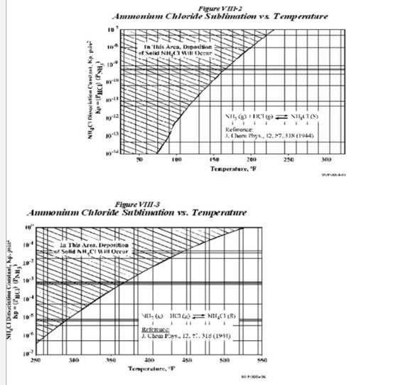
As seen from the charts, the deposition of these salts depends on the Kp values and the temperatures. The Kp values are obtained as follows
Kp(NH4Cl)= (PNH3)*(PHCl)
The charts also indicate that for the same Kp values, NH4Cl deposition occurs at a higher temperature as compared to NH4HS. The way to overcome this salt deposition is to inject wash water in order to dissolve the salts. As per UOP practice, the normal point of injection of the wash water is upstream of the REAC (Reactor Effluent Air Cooler). The temperatures experienced at the REAC are the area most prone to NH4HS salt deposition.
However as seen from the chart, NH4Cl has a higher sublimation temperature than NH4HS. These temperatures are often experienced at the Combined Feed Exchanger upstream of the REAC; hence there exists a possibility for salt deposition mainly NH4Cl at this region. In order to remove NH4Cl foulant, UOP has a water injection connection upstream of this CFE as well.
UOP normally suggests that wash water be injected periodically depending on the performance of the exchanger. But it is also not desired that water be injected continuously as it affects feed/effluent heat recovery and also can remove wash water from the normal injection point upstream of the REAC.
The points of injection of wash water should include those areas in the reactor loop where there is a possibility of crystallization of NH4HS or NH4Cl. The crystallization of these salts occurs at a particular Kp value dependent on the concentration of the salts as well as the temperature. The three primary aspects of wash water injection include
- The injection rate should be between 5-10% of fresh feed rate
- The maximum allowable concentration of NH4HS in the water after washing is 8%
- It should be ensured that at least 20% of the water remains in the liquid state after injection and does not flash.
The greatest effects of these salts occur due to their deposition in the tubes of exchangers resulting in very high velocities of flow and hence high levels of corrosion.
There are several other practices to minimize the possibility of NH4Cl salt deposition on the tubes. These include:
a. The nitrogen level in the feed and sulfur
b. The chloride level in the feed
c. The wash water quality
d. The sour water from the Cold Separator which has ammonium salts, H2S, NH3, Fe, and Cl.
UOP normally specifies the quality of wash water in the General Operating Manual (GOM) which is supplied to the customer. Regarding water quality the present water quality specification allowed is:
Total dissolved solids (TDC): 25 ppm (max) Dissolved oxygen: 0.05 ppm (max)
pH: 7 to 9
Chlorides (Cl-): 5 ppm (max)
NH3: 100 ppm (max)
H2S: 100 ppm (max)
UOP wash water injection practice allows up to 50% stripper sour water use from a dedicated sour water stripper. This is to guard against contaminants that could be in water from other units.
UOP’s stripped sour water quality should meet the following specification. TDS: less than 50 ppm
O2: less than 50 ppb
pH: 7 to 9
Cl-: less than 5 ppm NH3: less than 100 ppm H2S: less than 100 ppm
Since different crudes have different levels of sulphur, nitrogen and chlorides, it is impossible to have a single set regime for wash water as the appropriate point to inject water since it is also feed and operating condition dependent. If NH4Cl fouling is being observed, a regular regiment of periodic wash water will help to maintain heat exchanger efficiency. The frequency of wash water is determined on a case-by-case basis. However, removing the source of chloride in the feed or makeup gas is the best solution to avoid NH4Cl fouling in CFE.
Gregg McAteer (Nalco Company)
There are absolutely documented cases of organic chlorides coming in with certain crudes. Any chlorides that make it to a hydrotreater can react with ammonia to form ammonium chloride in the effluent stream and foul the exchangers. The salt is also corrosive, so the exchangers would foul and corrode at the same time. One location had the exchangers designed so they could bypass each exchanger in order to perform maintenance on failed exchanger tubes. The problem normally occurred in the 5th and 6th exchangers. They started up a water wash between the second and third exchanger and added a salt dispersant. The water wash has to be designed to reach dew point plus at least 25% in order to be effective. The salt dispersant will help keep the salts from building up on the tube surfaces. Together the water wash and the salt dispersant provided a long run (tripled the time between needing maintenance on the exchanger tubes).
David Krenzke (ART)
From our experience crudes do not naturally contain organic chlorides compounds. However, in some cases they become contaminated with organic chlorides from production additives or some in-refinery sources. Small amounts of chloride do not have a negative effect on hydrotreating catalyst performance. Initially the chloride will react with the alumina support to form aluminum chloride. This will then interact with trace amounts of water vapor in the gas phase to form hydrogen chloride which in turn reacts with the alumina support further downstream eventually reaching an equilibrium which will limit the concentration of chloride on the catalyst. The presence of HCl in off gas may, however present corrosion problems for downstream equipment.
Phil Thornthwaite (Nalco Company)
Earlier this decade, a number of European refiners received cargos of Urals crude (aka Russian Export Blend) that had high levels of organic chlorides. Experience in processing this crude suggested that this contamination was seasonal, and these particular cargos were received in early spring. It has been suggested that the levels of organic chlorides could be the result of them being used either in the crude production system to reduce wax deposition after the winter period or in the shipment process, where chlorinated solvents may be used to clean out systems, ship holding tanks, etc. Furthermore, crude quality varied significantly depending on the point of origin.
Other crudes have shown intermittent high levels of overhead chlorides and it has been suggested that this is a result of acid stimulation techniques used in the oilfield. These employ the use of hydrochloric acid to dissolve accumulated scales in the well thus improving the flow of oil. Under well temperatures and pressures, it is hypothesized that asphaltene hydrochlorides are formed and it is these that thermally decompose giving rise to elevated levels of chlorides. However, this form of organic chlorides presents the greatest risk to atmospheric and vacuum units and in some cases downstream conversion units such as visbreakers, cokers and RFCC’s.
The greatest risk to hydrotreating units is posed by organic chlorides is by the contamination of crude with chlorinated solvents. The portion of these solvents that do not thermally decompose can find their way into the lighter distillates such as the naphtha and kerosene fractions. When these streams are processed on a hydrotreater, they decompose to liberate hydrochloric acid and in the effluent stream of the reactor, they react with ammonia to form ammonium hydrochloride salts in large quantities. The generation of these large volumes of salt can lead to fouling of the feed effluent exchangers and downstream trim coolers that can in turn result in throughput limitations. Additionally, these salts can foul safeguarding equipment such as pressure relief and flow control valves and instances of salt related fouling could compromise process safety.
Another concern is the high rates of corrosion that can be observed due to these salts. The ammonium chloride salts are extremely hygroscopic and readily absorb water, even before the water dew point. Once water has been absorbed, a localized corrosion cell is formed that can lead to high rates of pitting corrosion leading to failures in the affected exchangers.
Gregg McAteer (Nalco Company)
A continuous water wash designed to reach dew point plus at least 25% is the minimum best practice. If monitoring or experience shows the problem to persist, then the addition of a salt dispersant is the next step. The question asks about water wash intervals, which implies that a non-continuous water wash would be a best practice – it is not. Many uses intermittent water wash, but this is not best practice. An intermittent water wash will cycle the exchanger surfaces from wet to dry to wet, etc. Ammonium chloride is hygroscopic, so water will be absorbed into the salt and hydrochloric acid will form between the salt and the exchanger tube causing pitting corrosion. The answer to question 17 gave an example of a water wash and salt dispersant used to give the refiner a long run on the hydrotreater.
Paul Fearnside (Nalco Company)
One of the downsides to using water washes within distillation towers is how the FeS scale is moved each time. After a few water washes the downcomer sections can become plugged with this scale. Better way is to utilize a salt dispersant such as that supplied by Nalco, without water, to keep these salts moving. This also alleviates the need to “slump “the tower for the water wash and does not reduce the tower throughput. These treatments can be intermittent or continuous depending on the severity of the salt fouling.
Phil Thornthwaite (Nalco Company)
The most common means for mitigating ammonium chloride salt deposition is with the installation of a properly designed wash water system. In order to provide effective wash water, the following aspects have to be carefully considered:
- Wash water source – the water should be of good quality and the primary contaminants to avoid are oxygen, hardness and high levels of filterable solids.
- Wash water injection rate – The wash water should be injected on a continuous basis and sufficient water must be added to the system to ensure that condensed water droplets are present and that the vapor is saturated (i.e., forcing the thermodynamic aqueous dew point). An excess is injected, typically 25%, is injected to ensure the vapor stream is saturated. The correct volume of water can be calculated from phase modeling.
- Injection location - key factor to consider is the layout of the heat exchanger network, as this will affect the distribution of flow and is likely to impact on the effectiveness of the wash water injection. Many overhead systems consist of multiple banks of exchangers in series and parallel, many of which are asymmetric in their layout. The liquid flow path in most cases is considerably different to that of the vapor and impacts the efficiency of the wash water injection.
- Equipment requirements - The method of injecting the water should be such that the vapor / liquid contact is maximized and that the water is distributed to all parts of the system. In order to ensure good distribution, spray nozzles are used (e.g., Spraying Systems Whirljet nozzle) in order to provide a full cone spray pattern with a small droplet size. Orientation of the nozzles must be co-current with the flow. Also, there should be the means to determine the water flow rate in order to provide evidence of flow.
When designing the wash water injection, the velocities of the system need to be considered. If the velocity is too high, there can be accelerated corrosion rates caused by water droplets impinging on equipment surfaces. Therefore, the location of the wash water injection is of critical importance, and it is common industry practice to locate the injection nozzle 10 pipe diameters upstream of any bends or elbows. However, it is prudent to routinely monitor immediately downstream of the injection nozzle and on the outer radius of the first elbow after the wash water injection.
The reliability and effectiveness of a wash water system can easily be compromised, even if properly designed. The following outlines some commonly found problems encountered:
-
Periodic Loss of Flow
-
Typically caused by solids plugging nozzles, valves and flow meters.
-
Insufficient Wash Water Rate
-
Unit conditions have changed since the system was designed
-
Partial plugging of nozzles, filters, valves & lines.
-
System operated intermittently rather than continuously
-
Poor Distribution of Water in the System
-
Incorrectly sized nozzles or no nozzles used at all
-
Incorrect orientation of nozzles
-
Incorrect location of nozzles
-
Low system velocities
-
Increased Corrosion Rates Observed
-
System velocities are high
-
Poor quality water sources (e.g. oxygen ingress)