
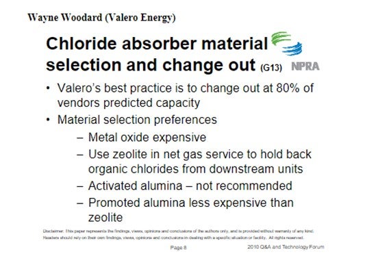
Question 38: What measurements and criteria do you use to decide when to change your gas and liquid chloride absorber material? How do you determine the selection of absorber material?
John Clower (Chevron)
For both gas and liquid service, Chevron monitors the inlet HCL/Total Chloride and replaces the adsorbent/molecular sieve based on material balance loading of chloride on the adsorber media. Chevron does monitor adsorbent outlet HCL/Total Chlorides, but as a best practice will change the adsorbent material before vendor maximum loading if breakthrough has not occurred. Spent adsorbent will become acidic and pass chloride as organic chloride to the downstream processes. Organic chlorides are difficult to detect by conventional tubes in gas service and will form HCL in downstream processing units.
This performance-based approach is not without problems, e.g., the accuracy of both chloride measurements and represented adsorbent capacity, and therefore requires a trial-and-error
approach.
Represented capacity of any chloride trap material will have been set the vendor to minimize high acidity conditions that lead to organic chloride and polymer (red/green oil) production. Commercially there are four main types of chloride adsorbent material available:
•Alumina
•Modified/Promoted Alumina
•Molecular Sieve
•Metal Oxide
Each of these materials is used in Chevron Refineries and joint ventures. Each adsorbent type will have various properties that can be used in making a decision on application:
•Total chloride capacity (HCL and Organic)
•Reactivity – potential for organic chloride and red/green oil formation
•Interferences (e.g., Sulfur)
•Cost per pound of chloride removed
Also, the design of the vessel used is important (L/D for adequate flow distribution, contact time) and can result in shorten life versus predicted breakthrough. Selection of adsorbent versus service will usually be made on a cost per pound of chloride removed.
Janel Ruby (Johnson Matthey Catalysts)
Chloride can be removed from streams using various products. These chloride guard products can differ in the way they are manufactured and in the way they work in certain applications, so it is important to choose the right one for your needs. The most common products are chemical absorbents or promoted alumina adsorbents. Chemical absorbents remove chlorides by irreversible chemical reaction, meaning that the chloride is chemically bound within the absorbent. Chloride removal in promoted alumina is accomplished mainly by adsorption in which hydrogen chloride is adsorbed onto the alumina surface. Both types of beds are non-regenerable and require change-out at chloride breakthrough.
When determining which product is right for a particular service, it is important to evaluate the operating parameters of the chloride guard bed. The location of the bed in the reforming flow sheet, the operating temperature of the bed, and the normal and maximum inlet chloride levels are important factors to consider when selecting an absorbent type.
Promoted alumina products are available for liquid and gas services. Promoted alumina can work over a range of operating temperatures but chlorides that are adsorbed onto the material may desorb at higher temperatures which will decrease the effectiveness of the product in these regimes. These products also have a lower chloride capacity usually ranging from 12 to 15% wt/wt, and require a high change-out frequency. An area of concern when utilizing promoted alumina materials is the formation of undesirable side products. When the chloride binds to the alumina surface of the guard material, it creates surface acid sites. The acidic surface of the material can catalyze side reactions and lead to the creation of organic chlorides or high-molecular weight hydrocarbons called “green oils.” Green-oils not only foul equipment, but also the guard bed itself, which can cause difficulties in bed discharge (increased purge time) and disposal.
Chemical absorbents are the most favorable option for chloride removal. These products are available for use in liquid and gas services. Chemical absorbents work over a wide range of temperatures. These products have high chloride pick-ups, for example PURASPECJM 2250 is a mixed metal oxide chemical absorbent which can achieve a chloride capacity of 30% wt/wt in non-fouling, gas phase applications. As previously stated, these products remove chloride through an irreversible chemical reaction. The alumina structure present in these types of chemical absorbents acts only as a binder which minimizes the tendency for unwanted side reactions. PURASPECJM 2250 can commonly be employed with the use of just a single guard bed.
There a few other considerations surrounding chloride guard bed materials. It is important to avoid two-phase flow in these beds as this will affect the performance of the chloride guard. Both promoted alumina products and chemical absorbents have a higher pick-up in gas phase, non-fouling and non-wetting applications. In liquid applications, diffusion through the liquid film around the chloride guard particle is the rate limiting step and capacities are generally lower than gas phase duties because of the mass transfer effects. Chemical absorbent products, PURASPECJM 6250 and PURASPECJM 6255 were designed to address this concern. These products have a high capacity and specific pore structure to allow improved removal capacity. They are comprised of the same chemical formulation and micromeritic properties but represent two differing particle sizes; PURASPECJM6255 is manufactured as a smaller sized sphere. The smaller size provides better performance as this minimizes the liquid film through which the HCl must diffuse, reducing the depth of the mass transfer zone and leads to higher average chloride pick at the point of HCl breakthrough.
The presence of HCl or organo-chlorides (RCl) in the exit stream of the chloride guard bed will indicate it is time to change out the material. The life of the guard depends on how the bed(s) is configured and what type of product(s) has been installed. Unless the bed needs to be shut down for inspection or is involved in a larger turnaround plan, chloride breakthrough will be the main reason for a shutdown to replace product. Regular testing for chlorides in the exit stream will help to determine when change out is needed. In applications with longer life cycles (years) testing may only be needed monthly until the bed is getting closer to its expected change-out interval. In applications with shorter life expectancies (months), the frequency of testing should be at least weekly.
Throughout the life of the bed, it is important to measure the HCl and RCl levels both inlet and exit the chloride guard beds. It has been shown that when promoted alumina is used for HCl removal, it catalyses the conversion of HCl to organic chloride species that can then slip from the bed. If the operator is only measuring for HCl then this chloride slip can go undetected until downstream issues occur. Chlorides passing through the bed can cause corrosion of downstream equipment and formation of ammonium chloride that cause fouling and blocking of equipment e.g., stabilizer columns, exchangers and compressors.
Year
2010
Process
Question 10: What causes metal-catalyzed coking (MCC) that obstructs catalyst circulation in CCR reformers? What actions do you take to mitigate MCC formation?
BILL KOSTKA (AXENS NORTH AMERICA)
Metal-catalyzed coke (MCC) formation typically occurs on 3d valence transition metals such as iron and nickel. Under CCR-like conditions of low hydrogen partial pressure (less than about 620 kpa), high temperature (more than about 480 °C) and low or stagnant flow, hydrocarbons can adsorb and completely dissociate on these metals. The resulting adsorbed, dissociated carbon can then dissolve into and change the metal structure. Once a nanosized portion of the metal becomes supersaturated with carbon, carbon begins to precipitate in a tubular crystalline form breaking the carburized-metal fragment away from the parent metal with the carbon nanotube continuing to grow between them. Despite their fragile appearance, these carbon nanotubes are incredibly strong and can readily damage equipment when present in sufficient numbers.
Mitigation of filamentous carbon growth is best achieved by reducing the possibility of hydrocarbon adsorption on the problematic iron surface. Two methods have been used to successfully achieve this goal in CCR reformers: 1) passivation of the metal surface with an adsorbate such as sulfur and 2) use of a more appropriate metallurgy.
Research done by HJ Grabke et al. has shown that very little sulfur, about 0.5 wppm in the naphtha feed, is required to adequately passivate the metallurgy of a CCR reformer. As a result, most CCR reformers are operated with roughly 0.5 wppm sulfur in the feed. Some refiners may rely on incomplete naphtha pretreatment to supply this sulfur, however, addition of a known amount of a sulfur-containing species to the feed ensures adequate passivation on a continuous basis.
Carbon steel is very vulnerable to MCC formation. Alloying carbon steel with increasing amounts of chromium and molybdenum reduces this vulnerability. These two metals tend to migrate to the steel’s surface and greatly dilute iron’s presence there. As a result, there are much fewer Fe-Fe neighbors necessary for hydrocarbon adsorption, dissociation and dissolution into the steel structure. A 9Cr-1Mo alloy steel greatly reduces MCC even at 650 °C. Utilization of this alloy with on-oil sulfur injection virtually eliminates MCC even at 650 °C.
DAVINDER MITTAL (HPCL Mittal Energy)
The catalyst circulation in CCR may be obstructed due to other reasons as well besides metal-catalyzed coking (MCC). However, the metal catalyzed coking presents a serious problem especially in low pressure CCR reforming units.
The processes of metal catalyzed coke formation will cause particles of the heater tube metal to break away from the tube surface. There is also an increased risk immediately following replacement of heater tubes. The coke formed in the furnace tubes may eventually migrate to the reactors and lodge behind the scallops or baskets. These coke deposits can grow until the scallops or baskets are deformed, affecting catalyst circulation, unit performance or even leading to an unplanned shutdown.
The recommended approach is to generally operate the Naphtha Hydro-treating (NHT) unit to remove essentially all of the sulfur in the feed. This will ensure that other contaminants (nitrogen, metals, oxygenates, etc.) are also removed from the feed to the extent achievable by the NHT. Organic sulfur is then added to the CCR reformer unit feed with a chemical injection system pumping in a specific and controlled amount of organic sulfur compound to achieve the target recommended by the licensor. This provides the refiner with independent control of the sulfur in the feed to the unit that can be changed as needed if feed rate or operating conditions change.
Our Continuous Catalytic Regeneration Reformer Unit was commissioned in May’2012. However, within one year of operation, the unit started experiencing several performance issues including restriction of catalyst flow in some of the spider legs of all 04 reactors , higher pressure drop and lower endotherm in reactors (more severe in 2nd Reactor, 60-70% of design value) and lower RON than design.
In view of the above issues, it was decided to shut down CCR during March-April’2014 and inspect reactors. Significant unexpected damage of reactor internals was found.
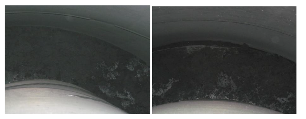
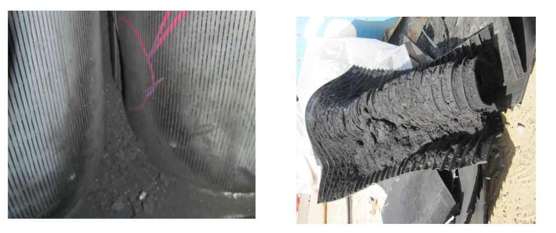
Picture-1: Huge quantity of coke in annular space between reactor grid and shell
Picture-2(a): Last panel of outside reactor grid found fully bulged with huge coke build up
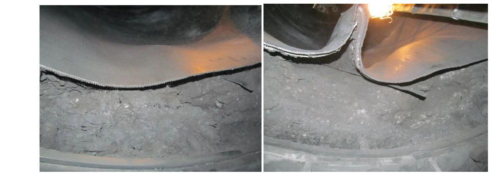
Picture-2(b): Last panel of outside reactor grid found fully bulged with huge coke build up
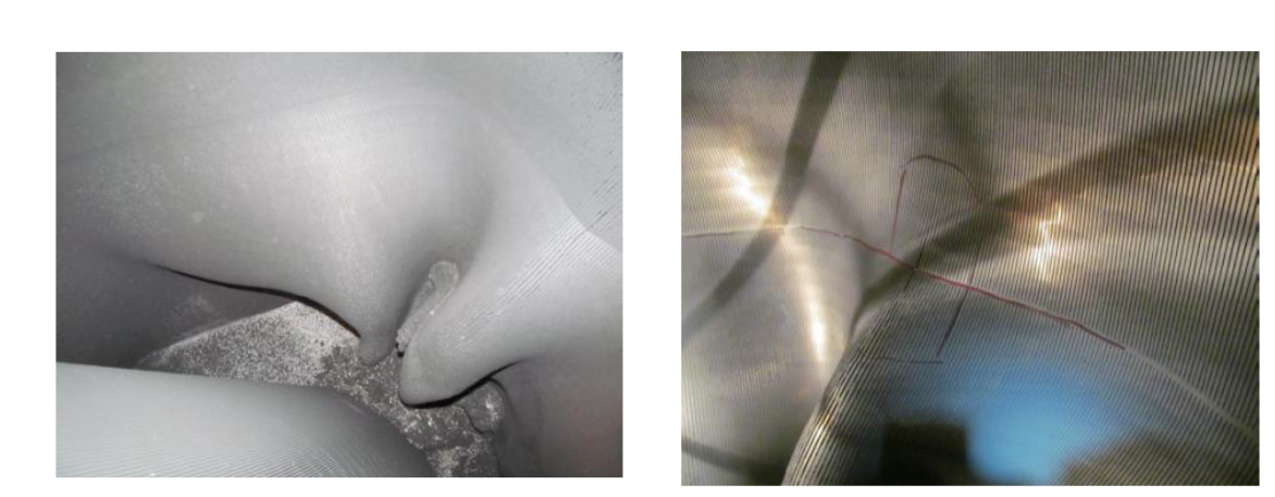
Picture-3(a): Shiny coke between and inside scallops leading to bulging and fish mouth cracks

Picture-3(b): Shiny coke between and inside scallops leading to bulging and fish mouth cracks
A joint root cause analysis with Licensor confirmed presence of Fe and carbon graphite (high carbon content) in the coke samples. During cleaning of the scallops, presence of lot of hard shining coke (metallic coke) was observed along with soft coke. It was concluded that coke build up in reactors/scallops/grids may have taken place due to metal catalyzed coking considering problem with DMDS dosing pump during initial year of commissioning as well as due to other reliability issues like frequent trip of recycle gas compressor. The presence of metallic coke in reactors may have acted as nuclei and further catalyzed the coke growth during recycle gas failure.
The heater tube thickness measurements also indicated some loss of thickness indicating metal catalyzed coking in addition to other forms of coke. The level of thickness loss was fortunately not alarming to inhibit future operation.
Based on root cause analysis certain recommendations were made to minimize metallic coking and damage to reactor internals.
Metallic Coke:
Maintain sulfur level 0.3 to 0.5 ppmw on CCR feed to be substantiated by presence of detectable amount of H2S in recycles gas and 100-150 ppmw of ‘S’ on catalyst sample.
Operate Naphtha Hydro-treating (NHT) unit to remove essentially all of the sulfur and other contaminants in the feed. Inject DMDS in CCR feed through dedicated facility to maintain recommended range of sulfur.
No flame sweeping/scattering on the furnace coils.
Maximum Tube Metal Temperature (TMT) to be restricted below 620oC.
Operation of heater burners within the design regime (maximum allowable process absorbed duty per burner: 1.0 Gcal/h).
Perform positive material identification of tube metal to confirm P9 (confirmed).
Other Coke/ catalyst agglomeration due to coke:
Improvement in reliability of recycle gas compressor.
Check for cold spider legs and try to restore catalyst circulation
Check for quality and temperature of net gas from CCR to avoid condensation in reactor spider legs
Maintain recommended coke ( 4 -5 wt%) on spent catalyst
Stress build up in Reactor internals:
Carry out emergency catalyst circulation in case of unplanned trip of the Recycle Gas compressor to relieve the mechanical stress built up due to difference in the thermal expansion coefficient between catalyst and reactors internals.
Year
2019
Submitter
Process