Breakfast
Session Start End
LEE (BP North America)
We have the chemical service vendor perform routine calculations for ammonia and/or amine salt points. We typically monitor the water dew point ourselves. The amine salt point is to be differentiated from the ammonia chloride salt point. Depending on the amine, a salt point can be higher, and often is. The amine, as opposed to the ammonia salt point, calculation is typically by special request if there are issues with the particular unit operating near the system’s salt point. It should be noted that data requirements for doing an in-tower amine salt point are more difficult and onerous than for doing an amine salt point in the cool tower overhead system for which the amine content in the sour water is readily available by direct analysis. The calculation for the in-tower amine salt point requires an estimate of the amine quantities feeding the crude tower and prior to any overhead chemical injections.
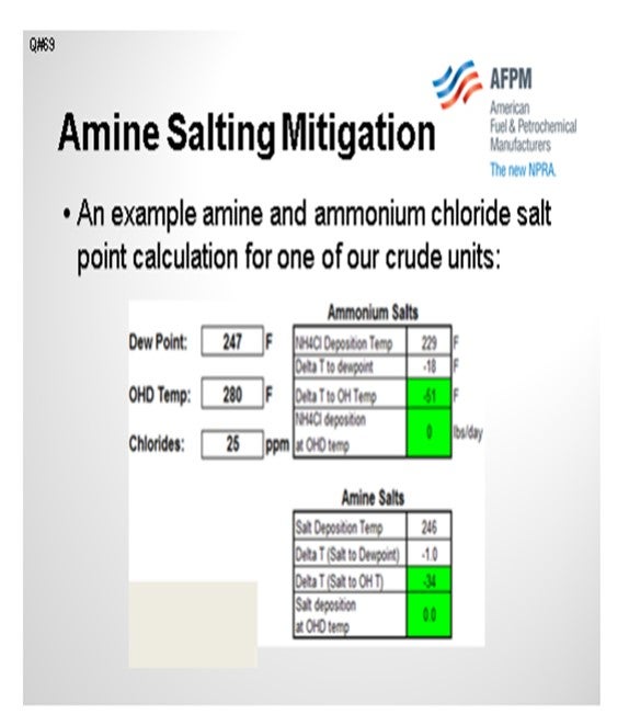
The table on the next slide shows some amine salt points for one of our crude tower overheads and compares them to the ammonium chloride salt point. In this example, the ammonium chloride is in the 229°F range, and the amine salt is 246°F in the crude tower overhead system. We try to maintain the top pumparound return temperature above the controlling salt point. We also try to operate the bulk top temperature at least 40°F above the controlling salt point. But recently, there has been a tendency with commercial drivers to reduce top temperature targets in order to maximize jet or light diesel production over naphtha production.
If the system is in a troubleshooting mode and corrosion is suspected, then samples are taken from any deposits in the top pumparound circuit and analyzed for amine, nitrogen, and chloride content. Of course, if corrosion products are present, they will be evident by significant iron and other inorganic content in the foulant samples.
Some other mitigation handles on amine salt formation include the following:
1. Optimize desalter performance to reduce hydrolyzed chloride content in the crude tower overhead. There are multitudes of desalter optimization parameters, including washwater rate, washwater quality enhancements (including pH and ammonia content), mixed valve pressure drop optimization, demulsifier use, and optimization of grid voltage settings to achieve the maximum operating temperature.
2. Use caustic injection as an operating handle if caustic injection skids and the injection quill are already available on the unit. About half of our units practice caustic injection to mitigate the chloride’s contribution to amine salt formation.
3. Review filmer or neutralizer formulation with the chemical service provider. Certain filmers and neutralizers have slightly lower amine salt point than others, and there are tradeoffs in performance.
4. Operate the top temperature of the crude tower or elevated temperature, which will increase the operating margins of the salt point. This is in commercial conflict with the typical current financial drivers to minimize overhead naphtha production while increasing jet or kerosene. There will be short-term yield optimization versus long-term availability tradeoffs.
5. If possible, increase the top pumparound return temperature. Again, the idea here is to increase operating margins to the system salt point while trying to maintain the required crude tower heat removal.
6. Perform continuous washwater injection at the location of salt deposition.
DION (GE Water & Process Technologies)
As previously discussed, the ionic equilibrium model is an extremely important tool to define the safe operating envelope for your unit. Most specialty chemical suppliers have an ionic equilibrium model. GE’s ionic equilibrium model is called LoSalt*. I cannot stress enough the importance of running these models as frequently as possible. Various scenarios can be examined in advance to predict when particular parameters would increase the risk for salt corrosion. Different neutralizing amines will have different salt points. Selecting a low salting amine will minimize salt corrosion potential. Then explore the other parameters, such as the upper limit for tramp amines, chlorides, and stripping steam. The best-in-class corrosion control program will look at all of these factors: metallurgy, mapping and eliminating tramp amines, overhead waterwash, an effective filmer, and the appropriate neutralizing amine.
DEAN WONG (Husky Energy)
We have heard a lot of good information about desalting operations, but does the panel have experience removing crystalline salts as the feed gets heavier, the easy salts?
DION (GE Water & Process Technologies)
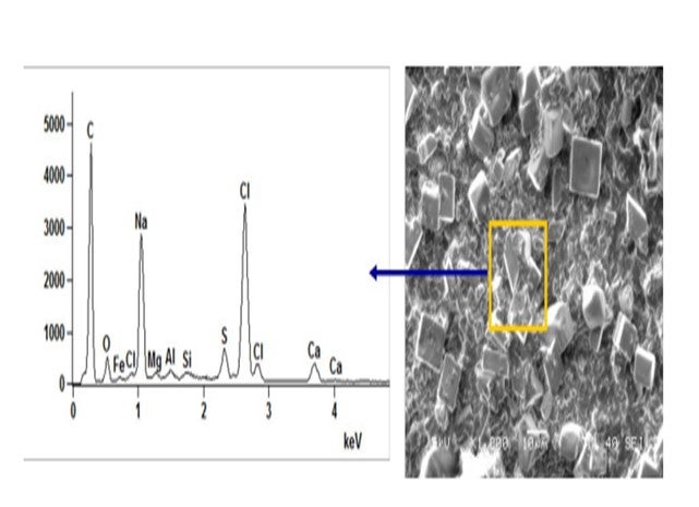
Crystalline salts exist in crude. Below is a microscopic picture and analysis of raw crude after filtration. The topic of “encapsulated” or “asphaltene-coated” salts has been mentioned in the past. In general, their removal can be improved by working the desalter harder. The crystalline salts must contact the washwater to be removed from crude. The desalter is designed to make an emulsion, wash impurities from the crude, and then resolve the emulsion. A finer emulsion, using mix valve and washwater rates, can be utilized to improve salt removal efficiency. The Salt by Extraction Test should measure all extractable chlorides. The procedure includes adding hot toluene to the crude in a separatory funnel. In theory, the toluene should remove the heavy oil and asphaltene coating from the crystalline salts.
RUSSELL STRONG (Champion Technologies)
I love this topic, but I will not take too much time. Let’s go back. The question says, “How do you detect if amine salts are forming and causing corrosion?” I will read that as “…have formed and are causing corrosion”. A main consideration has to do with neutralizer injection. In the case of a neutralizer, if it goes in as a liquid, which is typical, then it will take time for it to absorb the latent heat. The neutralizer will need to evaporate in order to work according to modeling. In the course of that evaporation, it will have ample opportunity, while as a liquid, to react with HCl vapor. That problem is seen in a lot of refineries, particularly if they do not have the right kind of injection system to inject the neutralizer as a vapor.
In some cases, even if you think you have a good injection system, you may still have a similar problem. A high concentration of salt can form, caused by amine recycling to a higher and higher concentration. Modeling may not have adequately considered the amount of neutralizer partitioning into reflux and/or into the desalter crude, which then cycles back to the overhead.
All that being said, let’s get to the question of detection. You can usually tell if salts have formed ahead of the water dew point. Pull out a corrosion probe/coupon from upstream of the calculated water dew point and examine it using EDS-SEM (energy dispersive spectroscopy-scanning electron microscopy) analysis. You can see any chloride that may be on that probe/coupon. The chloride will have been deposited in a salt form. HCl vapor is certainly not going to condense ahead of the water dew point.
The trouble with knowing whether or not it is an amine chloride, ammonium chloride, or some other form of chloride is that when corrosion occurs, the salt forms metal-chloride. The amine/ammonia has nothing to hold it in place. It tends to evaporate away from the deposit, and subsequent examination will show significantly less amine than was originally present. Alternatively, if you cannot do the above analyses, a chloride salt on your corrosion probe, on which you had an amine salt or an ammonium chloride salt, tends to top out around 50 mils a year unless there is a velocity-assisted component that accelerates the corrosion. If it is less than that, the problem is not as serious as it could be.
DION (GE Water & Process Technologies)
A more complete understanding of the overhead system dynamics is the first step in properly diagnosing the corrosion and fouling potential of a given unit. In the past, this has been accomplished retroactively following the failure of system equipment. However, a proactive approach to amine salt precipitation prediction and corrosion mitigation is a much more efficient way of controlling overhead corrosion. A highly effective means of determining the formation of amine salts is through the use of ionic modeling software. The use of a robust and rapid ionic modeling tool will allow for the calculation of the salt precipitation temperature, or “salt point”, of the neutralization salts and water dew point (ICP) temperature. The use of such a model allows for rapid evaluation of current system variables and operating parameters. With this information, asset operators can potentially adjust tower operating conditions (e.g., overhead outlet temperatures) to manipulate the location in the overhead system where the neutralization salts precipitate. Use of the model also allows for the development of an “operating envelope” for the tower and overhead system that keep the amine salts from forming in unwanted areas of the overhead circuit across various desalter effluent chloride ranges. GE has successfully implemented this control and mitigation approach at a client site using its LoSALT* Ionic Modeling Tool and the refiner first consults with the local representative to evaluate potential tower operational changes prior to adjusting process conditions.
Beyond operational adjustments, a “three-prong” approach of neutralizer, waterwash, and filming corrosion inhibitor should be employed to mitigate corrosion by amine salts. First, an appropriate neutralizer must be selected to minimize the neutralization salt precipitation temperature while effectively controlling ICP and accumulator pH within acceptable ranges. Lower salt-point amines should be utilized in the overhead treatment program to minimize salt formation in the overhead system ahead of the water dew point or in the fractionator tower itself. Secondly, an effective waterwash protocol must be implemented to raise the amount of free water in the system and provide a means of washing away any precipitated amine salt deposits. The last portion of this chemical treatment approach is to introduce a quality filming corrosion inhibitor to protect the metal surfaces against corrosive attack. Some quality filmers will provide a level of salt dispersions to further aid in the movement of amine salts through the system and reduce underdeposit corrosion related to these salts.
Tramp amines that enter the distillation column with the desalted crude contribute to higher salt point temperatures in the overhead. An often-overlooked operational strategy is source-reduction of the tramp amines that would drive the overhead salt point to higher temperatures. Developing an amine-map of the refinery’s amine sources can aid in rapidly identifying and eliminating tramp amines entering the overhead system. Additionally, chemical treatments can be implemented at the desalter to increase amine extraction into the desalter effluent brine and prevent them from reaching the tower overhead.
BASHAM (Marathon Petroleum Corporation)
Ionic modeling is the only way to predict. High pressure drops across the top couple of trays could point to a buildup of fouling material from corrosion. The top temperature of the crude tower should stay above 300°F to ensure that no corrosion happens in the tower. Consideration should be given to ensuring that the top pumparound return temperature is well above the water dew point temperature to avoid shock condensation of water vapor. Also, reflux should be introduced onto the top tray with a spray header to allow it to heat up and not cause shock condensation.
RANDY RECHTIEN (Baker Hughes)
The best method for determining the formation potential of amine-HCl salts is the use of Baker Hughes Ionic Model technique. This method provides for the rigorous calculation of salt formation temperatures under all operating scenarios. Once the root cause of the salt formation has been determined, multiple mitigation options can be examined using the Ionic Model. These mitigation options include the following:
• Improved desalting operation to reduce overhead HCl levels,
• Caustic injection to desalted crude to reduce overhead HCl levels,
• Application of alternative neutralizers with lower salt-forming tendency,
• Installation of continuous waterwash to the overhead, and
• Increased tower operating temperatures.
DENNIS HAYNES (Nalco Energy Services)
Salt formation in towers would result in restricted flow and reduced distillation performance. Where salt formation is towers is suspect, as tower scan would assist in determining location and severity. Overhead lines that are suspect for salt formation should have UT reading periodically done and changes in corrosion rates would be an indication. Both of these points are after-the-fact measurements; so more importantly, utilization of modeling to determine salt points in process towers would lead to an early indication of potential problems.
When salt has formed and needs to be dealt with salt dispersant chemistries have an effective history in the industry. Operationally, slumping the tower and applying a waterwash is possible; however, much planning and care is required due the introduction of water into a potentially hot system. If salt formation is possible, washwater, additional steam, adjusting tower temperature, and pressure are all variables that may be used to change dew point and salt points.
BASHAM (Marathon Petroleum Corporation)
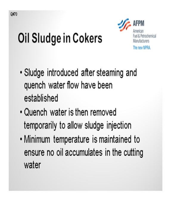
One of our delayed cokers does process crude rag layer draw, wastewater sludge, and oily water. I think they primarily process the crude rag layer, however. What we do here is introduce the sludge after we have steamed the coke bed and established the quench water flow. We then temporarily remove the quench water to allow the sludge injection, and then we maintain a minimum temperature – I think it is around 600°F – to ensure that no oil accumulates in the cutting water. We also have to take a look at the cutting water to check for any emulsion. If it is milky-looking and has a foul odor, then we know we probably have either too much injection or our temperature is too low.
TRAN (Houston Refining LP)
We do a similar process at one of our delayed cokers at the Houston Refinery. I want to add that we have experienced hot drums issues due to sludge processing the slurry. When we did the particle size distribution, we found that the volume of solids in the water injection was higher than typical, as was the size itself. We mitigated it by reducing the injection rate and the number of solids in the slurry mixture, and then requested that the site itself grind it down a little smaller.
MIKE FINK (CITGO Petroleum Corporation)
What sort of limits do you put on percent oil and percent solids?
TRAN (Houston Refining LP)
We try to keep the solids to under 1%. In terms of micron size, the majority of it is typically below 25µ (micron). The whole range is up to about 100µ.
AHMAD AL-JEMAZ (Kuwait National Petroleum Company)
Can you still maintain anode-grade qualities affecting the sludge in the coker?
BASHAM (Marathon Petroleum Corporation)
Yes, we can.
TRAN (Houston Refining LP)
We do not have any experience producing anode-grade coke.
AHMAD AL-JEMAZ (Kuwait National Petroleum Corporation)
What are the specific parameters that you monitor in the sludge to avoid affecting the coke quality?
BASHAM (Marathon Petroleum Corporation)
As Don mentioned, some of the parameters are particle size and amount of sludge being injected. You also have to watch the minimum temperature, as I mentioned. That is all the experience that we have on it. We do not do a lot of injection, but I am not aware that we have had any coke quality issues. The primary concern is the effect on the cutting water.
BASHAM (Marathon Petroleum Corporation)
One of our delayed cokers processes a crude rag layer draw, wastewater sludge, and oily water. These components are processed after steaming and establishing flow with the quench water. Quench water is removed temporarily to allow injection of the sludge. After the sludge injection is complete, quench water is reintroduced. To minimize the potential for accumulating oil in the cutting water, the amount processed and the minimum temperature of the coke drum minimum temperature are both regulated.
TRAN (Houston Refining, LP)
We process slurry between the steam stripping and water quench steps. We limit the slurry injection amount based on the coke drum outlet temperature. The slurry stream contains solids which can cause reliability issues on pipes and pumps. We have also seen coke bed plugging issues that have resulted in hot drums and fallout. Some of coke morphology issues have been alleviated by reducing the slurry injection rate, the solid amount in the slurry, and the solid sizes.
LEE (BP Products North America)
We have some experience with quench injection as a method of recycling sludge in the coker. This involves injecting it with quench water at the beginning of the coke cooling step. To minimize problems and maximize sludge processing a refiner should: Prepare the sludge to have little or no free oil and small particle sizes (usually performed by an experienced contractor; centrifuge to recover free oil and grind to obtain small particle sizes), and strictly limit the amount of sludge injected (usually limited by a combination of time, quantity and/or drum temperature). It is important that the sludge injection is discontinued at a drum outlet temperature of not less than 550ºF to insure the oil is recycled through the blowdown system. If not done correctly, sludge processing on the coker can contribute to severe odor problems when the drum is opened and with the coke in storages, problems with drum cooling if the sludge particles are too large (can contribute to water channeling and subsequent hot spots/eruptions), problems with draining the coke drum prior to decoking, and increased coke toxicity and industrial hygiene issues.
Active drum sludge coking is another option where this sludge is slurried with oil and injected into the coke drum during the coking phase. BP has one site that does active drum sludge injection through the top of the drum. Sludge injection during the coking phase takes up some coker capacity. Typically, there are not the same problems with odorous coke. Injection rates need to be as low as possible to prevent lowering the drum overhead temperature and increasing coke make and preventing the coking reaction temperatures from being too low. Sludge injection should be discontinued approximately three hours prior to the drum switch to get the drum outlet temperatures up to convert any unreacted material.
DION (GE Water & Process Technologies)
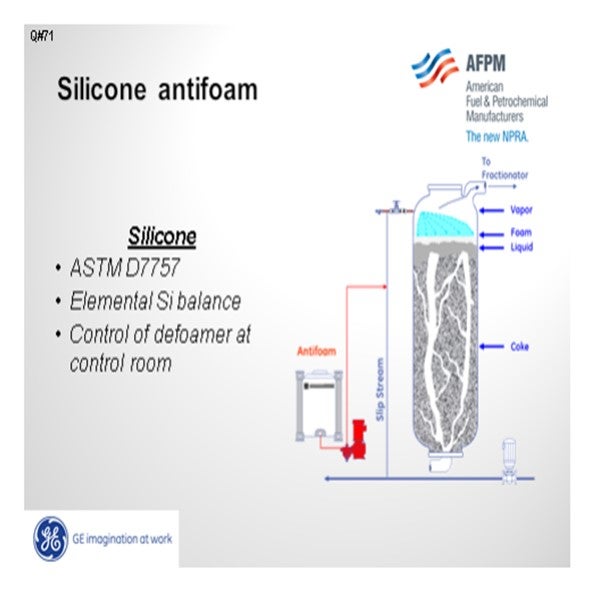
Don mentioned the ASTM test procedure. It may also be beneficial to conduct elemental silicon loading. Silicone is a known molecule: dimethylpolysiloxane. The amount of elemental silicon introduced into the drum over a period of time can be tracked and compared with silicon in the distillate. Generally, the biggest step change to silicon loading is improving the chemical feed system. At the beginning of the drum cycle, little to no defoamer is required. Near the end of the drum cycle, copious amounts of defoamer may be required to prevent a foamover. Using a variable speed motor or solenoid valve on the feed system, with control at the board room, can reduce overfeeding the silicone, hence reducing downstream silicon poisoning concerns.
TRAN (Houston Refining, LP)
To test for silicon content in the coker naphtha streams, we use the ASTM D7757: the Standard Test Method for Silicon in Gasoline and Related Products by Monochromatic Wavelength Dispersive X-ray Fluorescence Spectrometry. Our main KPI (key performance indicator) is the amount of silicon loading on the downstream coker naphtha HDS (hydrodesulfurization) catalyst bed.
We track daily and monthly antifoam usages and compare them to industry low antifoam users. Typically, we are in the range of 1.2 to 1.5 gallons per thousand barrels of fresh feed versus 0.8 gallons per thousand barrels of fresh feed.
The coke drum foaming tendencies can vary greatly with resid feed qualities. For the resid feed with high foaming tendencies, our antifoam usage can increase by three to five times the normal antifoam usage. In these cases, we perform temperature ramp at the end of the coking cycle to stabilize the foam front and adjust unit charge rates and cycle time to achieve higher drum outages.
DION (GE Water & Process Technologies)
The standard for determining silicon content in gasoline and other products is ASTM D7757: the Test Method for Silicon in Gasoline and Related Products by Monochromatic Wavelength Dispersive X-ray Fluorescence Spectrometry. ASTM D7757 determines total silicon by monochromatic, wavelength-dispersive X-ray fluorescence spectrometry in naphthas, gasoline, RFG, ethanol and ethanol fuel blends, and toluene at concentrations of 3 mg/kg to 100 mg/kg.
In addition to measuring elemental silicon concentrations in fuels, the user of silicone antifoam can readily calculate the elemental silicon loading per drum cycle. GE Water & Process Technologies has a long history of providing state-of-the art silicone antifoam products, application procedures, automation packages, and onsite technical assistance.
LEE (BP Products North America)
We are not so sure about a test method per se, but one can look at the effectiveness of an antifoam agent if the drum is equipped with some form on continuous level monitoring. Monitoring silicon pounds per 1,000 bbl (barrel) of unit feed is a good practice to give a relative idea of dosing rates. One can also sample different product streams at various times while injecting silicon to try to give an idea of how much silicon the different fractionator products might have. With a continuous level indication or enough of the neutron backscatter points on the upper section of the coke drum, the decrease in foam layer when antifoam is added is really the only metric for showing that the antifoam is working.
ROGER METZLER (Baker Hughes)
Yes, silicon content analyses of the cracked liquid products can be measured by a variety of techniques. However, some of the Si fragments are volatile. Therefore, test methodology needs to allow for measurement of both volatile and nonvolatile Si. Baker Hughes analytical techniques measure both volatile and nonvolatile Si components in coker distillate liquid product streams. Baker Hughes FOAMSTOP™ Low Catalyst Impact delayed coker antifoam/defoamer can reduce Si contamination in these coker distillate liquid product streams. BASHAM (Marathon Petroleum Corporation) The glass coker apparatus at the University of Tulsa Coker Joint Industry Project (JIP) lab is used to measure antifoam effectiveness. The time it takes for foam to rise to a given level is measured after injecting a known quantity of antifoam. The longer it takes for the foam to rise, the better the antifoam performance
SHELTON (KBC Advanced Technologies, Inc.)
Sim Romero with KBC, who is sitting in the audience, will be conducting Coking 101 and will cover these topics. Since I am repeating Sim’s responses, I will summarize the answers. The question was about Best Practices for steam rates, heater velocity steam, valve purges, and drum steamout. It is difficult to give a rule of thumb for velocity steam, but we always find that the maximum allowable is the best.

We model the heater to determine the optimum velocity steam. The only potential limits are downstream including excess heater ΔP (differential pressure), coke drum velocity, fractionator flooding, vapor jet flooding, main fractionator overhead heat removal, and downstream sour water treatment. But pressed to give a number, we say that it is usually greater than 1 wt% (weight percent) of the heater feed, not of the fresh feed. Of course, high asphaltic crudes with high asphaltene contents require more steam to obtain the desired run-length. We use the KBC VIS-SIMTM model which predicts fouling and run-lengths based on feed quality and operating conditions.
Heater Geometry: Sim wants to point out that fouling is a function of the asphaltene deposited on the tube wall, so velocity steam increases shear forces and tends to strip off the asphaltene deposit to lower fouling. Purge steam is usually specified by the valve manufacturer to prevent the valve from sticking or leaking,
Drum Steamout: Most operating companies start slowly to avoid a disaster. Once the operation is in good shape and there is no risk of foaming, the steamout can proceed.
Fractionator Blowdown/Steamout: The rates and duration are dependent on the operation and, especially, the type of coke formed. It would be site-specific. The drum geometry would also affect the duration of steamout to the fractionator versus blowdown. Of course, the blowdown system limits may affect how long the steamout is through the fractionator and then switched to the blowdown.
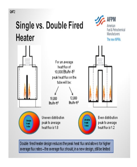
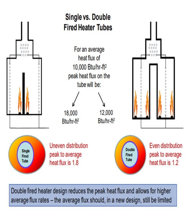
There was a question about the new double-fired heater designs using less steam. Again, we have to model the heater. We can say that if the design were 10,000 BTU/hr-ft2 heat flux for a single- versus a double-fired heater, then this would be the difference in peak temperature. The peak temperature is about 1.8 times the average flux for a single-fired versus 1.2 for a double-fired heater. In theory, if they were both designed for 10,000 BTU/hr-ft2 , then the double-fired heater would use less steam. However, we frequently see heater vendors providing double-fired heaters at relatively high flux rates.
BASHAM (Marathon Petroleum Corporation)
I want to expand a little on Al’s points about double-fired heaters. In Robinson, we are currently replacing the four-pass single-fired heater with a three-pass double-fired heater. The design steam rate is about 25% less. As Al mentioned, the average heat flux is higher, which translates to fewer passes and lower steam rates that are required.
The purge steam to the valves will be dependent upon the manufacturer. For a large two-drum coker, we typically see it somewhere around 6,000 lbs/hr (pounds per hour). When you look at all of the other steam on the structure with the orifices, it could be up to 18,000 lbs/hr. Drum steamout for our large 30-foot diameter drums can be up to 30,000 lbs/hr, including steaming to both the coker fractionator and the blowdown drum. So, a considerable steam load is required.
SHELTON (KBC Advanced Technologies, Inc.)
KBC’s Best Practice for heater velocity steam and valve steam is to maximize steam rates within operating limits. Potential limits to higher steam rates are summarized below.
1. High velocity steam rates increase heater pressure drop and can result in hydraulic limits.
2. Excessive coke drum velocities can cause solids carryover or foaming.
3. High fractionator velocities can cause flooding and poor separation.
4. Fractionator overhead heat removal may limit steam rates.
5. The capacity of downstream sour water treatment facilities may be limiting.
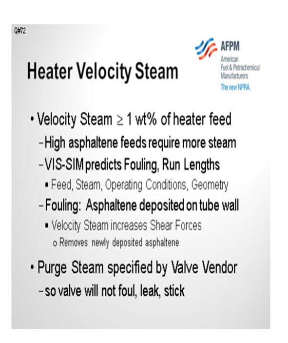
KBC has developed a rigorous thermal kinetic heater model VIS-SIMTM that predicts heater fouling and can be used to estimate run lengths based on operating conditions and heater geometries. Simulations show that velocity steam rates should be approximately 1 wt% or more of the heater feed. Steam rates are dependent on feed rate and feed quality. High asphaltene coker feeds require more steam than low asphaltene feeds at the same rate. Some operators limit velocity steam due to concerns that high velocity steam could cause annular flow in the heater. Simulations show just the opposite; higher steam rates move the operation further away from annular flow.
Fouling in coker heaters is a function of asphaltene deposited on the tube wall and stress forces tend to strip newly deposited asphaltene from the tube walls. Velocity steam increases shear forces which remove newly deposited asphaltene and reduces fouling.
The amount of valve purge steam is determined by the valve manufacturer. If minimum steam purge rates are provided for a drum switch the valve will not foul, leak or stick. Ensuring that the correct amount of steam is actually delivered to the valve can be challenging. The steam required during a drum switch can significantly increase coker steam loads. Supply steam header diameters and lengths can limit the amount of steam that can actually be delivered. Best practice is to install a steam flow meter on the total steam to the switch deck so that changes in operation can easily be monitored.
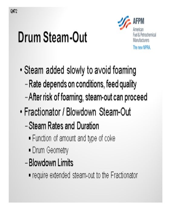
The initial steam stripping step immediately after a drum switch can cause foaming in the coke drum. Adding stripping steam must be conducted slowly and carefully to avoid foaming or re-foaming in the coke drum. This is highly dependent on operating conditions and feed quality. Once steam is fully introduced to the full drum and any risk of foaming has passed, then the steamout can progress. How much steam is required (flow rate and duration) for both the steamout to the fractionator and the blowdown is a function of the amount and quality of the coke and drum geometry. Additionally, limitations in the blowdown system may require extended steamout to the fractionator.
A double-fired heater design generally has a lower peak heat flux, but it is designed with a higher average heat flux. Additionally, a double-fired heater has a lower residence time.
The high average heat flux would imply a higher fouling rate. Without a detailed design comparison, it is not possible to evaluate whether more or less steam is required for a double-fired heater.
A poorly designed double-fired heater with an average radiant heat flux greater than 14,000 BTU/hr-ft2 or a heater operating at higher feed rates than the original design will require more velocity steam.
The effects of single versus double-fired coker heater designs on peak heat flux for an average heat flux of 10,000 BTU/hr-ft2 are shown below.
BASHAM (Marathon Petroleum Corporation)
Heater Velocity Steam: Velocity steam promotes vaporization and reduces heater tube residence time, both of which reduce the fouling rate. Optimal velocity steam rates may depend on heater design, feed composition, feed rate, and recycle rate but are typically between 0.60 wt% and 1.2 wt% of the feed. Too much velocity steam can cause high heater tube pressure drop, excessive sour water make, high coke drum velocity, and high coker fractionator loading.
At Marathon Petroleum Company (MPC), we performed test runs where velocity steam was raised from 0.60 wt% to 1.2 wt%. We saw a marginal reduction in the heater tube fouling rate, but it was not significant enough to justify the increase in velocity steam.
We are currently replacing a four-pass single-fired coker heater with a three-pass double-fired design in one of our refineries. The design velocity steam rate for the double-fired heater is 25% less than what is currently used in the single-fired heater. The average flux of a double-fired heater is higher than that of a single-fired heater for the same tube metal temperature. This means that less radiant heat transfer surface area is required (fewer passes), and, hence, lower steam requirements.
Valve Purge Steam: Valve purge steam consumption is highly dependent on valve design/manufacturer. For a ball valve with steam energized bellows, the steam consumption can be significant. Steam balances based on a ball valve manufacturer’s estimate a valve purge at around 6,000 lbs/hr for a large two-drum coker. There is an additional 12,000 lbs/hr of steam usage from the orifices around the drum structure for a total of around 18,000 lbs/hr.
Drum Steamout: The purpose of the drum steamout to the fractionators and blowdown is to clear the feed line of resid/pitch and provide a clear channel for the water to flow through. It also helps transfer heat from the coke bed to the unconverted pitch on the top of the coke drum to complete the coking reaction.
Recommended steam rates and duration will vary based on drum size, as well as coker licensor design and preference. At MPC, we currently steam the larger 30-foot diameter drums to the coker fractionator for a minimum of 30 minutes at a rate of 15,000 lbs/hr to 20,000 lbs/hr. These drums are then steam to the blowdown drum for a minimum of 30 minutes at a rate of 20,000 lbs/hr to 30,000 lbs/hr. We steam our 22-foot diameter drums at rates of 5,000 lbs/hr to the fractionator and 12,000 lbs/hr to the blowdown drum for a combined duration of 30 minutes.
LEE (BP Products North America)
Furnace velocity media [steam or BFW (boiler feed water?)] injection rate is ~1.0 wt%. The primary reason for this rate is to minimize heater fouling. At some velocity the impact of more velocity media has limited effect. Injecting BFW requires additional heater duty to vaporize the water. The same is true for steam, but the amount of duty increase is small. Automating velocity steam control to increase velocity media as the oil charge rate decreases, and to reduce velocity media as the charge rate increases, can help maintain desired coil velocity. Valve purge steam requirements are dependent on the manufacturer and type of valve. Many ball valves require continuous steam purges. The wedge plug style uses steam only when the valve is moving from one position to the other. Steamout of the coke drums is necessary to remove O2 that is present prior to warming the drum up. Purge the drum with enough steam to turn over the drum volume at least five times to get the oxygen concentration low enough to prevent hazards in the gas plant downstream.
BASHAM (Marathon Petroleum Corporation)
We have seen coke beds collapse during the beginning stages of the quench water addition. We have had operational problems because we were not able to get the quench water into the coke bed. We even tried alternating back and forth between the stripping steam and the quench water, but we were not able to penetrate the coke bed with the quench water. The only option that we had at that point was to quench the coke bed using the top water quench. That usually takes a lot longer. In most designs, if you have a top water quench, it is smaller piping. It has been an issue that we have seen if there have been different types of crudes and highly paraffinic crudes are being mixed with asphaltenic crudes. In fact, that is the only time that we really saw this type of coke bed instability.
Some of the causes, as I mentioned, are the feed quality and if you have a low binder content, insufficient steaming, or if you interrupt flow during the water quench step. As far as preventions, we tried to increase the stripping steam immediately at drum swap. You can also increase the stripping steam rates when you are steaming to the blowdown drum. If you are steaming into the fractionator, you have to be careful not to overwhelm your overhead cooling capabilities. You want to try to ensure a smooth transition from your stripping steam step to the water quenching. If it is possible, you can add a small amount of FCC slurry to help bind the coke.
BASHAM (Marathon Petroleum Corporation)
We have seen instances where the coke bed collapsed during the beginning stages of the water quench step. The collapsed coke blocks the bottom drum feed piping and prevents quench water from flowing up through the coke bed. We have tried to alternate steam and water flows to unblock the feed piping, but this has proven to be unsuccessful. Our only option to quench the drum has been to use the top water quench piping and carefully quench the coke bed from the top down.
These are several reasons for coke bed instability, including:
1. Insufficient steaming of the coke bed after switching feed to another drum,
2. Feedstocks that produce a soft coke having low binder content, and
3. Flow interruption during the water quench step.
Practices to try to minimize coke bed stability are as follows:
1. Increase stripping steam immediately after the drum switch to help clear the feed line and ensure channels in the coke bed are open. Be mindful of fractionator overhead cooling limitations and watch for any coke bed lifting.
2. Increase stripping steam rates when steaming to the blowdown drum.
3. Ensure a smooth transition from stripping steam to quench water addition. Stopping the flow of steam or water can result in collapsing the coke bed channels.
4. Adding a small percentage of FCC slurry to the feed can help bind shot coke and reduce hot spots by improving coke bed permeability.
TRAN (Houston Refining, LP)
We have experienced coke fallouts after removing the drum bottom head and also coke bed cave-ins while drilling. Typically, we adjust the coker heater outlet temperature to shift coke morphology. Fluid catalytic cracking light cycle oil and heavy cycle oil can also be injected in the feed to bind the loose shot coke. We have installed automatic bottom unheading devices to eliminate exposure of the operator when the coke drum bottom head is removed. When the drill bit is stuck due to bed cave-in, we fill the coke drum with water and float the drill bit out of the collapsed coke bed.
LEE (BP Products North America)
Some cokers have reported some coke bed instability at the top of the coke bed (top of the bed shifting or fluffing up). Our experience has been that this is due to having too low a coking temperature. Increasing temperature has been helpful in addressing this issue, sometimes for the full coking cycle and sometimes for the final few hours of the coking cycle. Inadequately drained drums can also cause coke fall out. Relatively soft coke produced from paraffinic resid can cave in during drilling, soft coke produced due to low drum temperatures can cave in during drilling, and loose shot coke will flow out of the coke drum when the bottom head is removed. There is lots of experience with many different potential causes.
TRAN (Houston Refining LP)
At one of our two cokers, we use ring joint flanges from the coker heater outlet to the coke drum inlet and have had no leak issues. At the other coker, we have a short section of piping at the coke drum feed inlet that had raised face (RF) with spiral wound gasket drum (SPWD) that would occasionally leak. We changed the gasket type to INCO625 RF and Belleville washers, which significantly alleviated the leak issues. During the upcoming turnaround, the area with INCO625 RF will be changed out with new piping that will take RTJ (ring-type joint) flanges.
BASHAM (Marathon Petroleum Corporation)
To echo Don’s points, we also use the ring joint gaskets and flanges on the piping from the coker furnace outlet to the drum inlet and then over to the fractionator. We also use the Belleville washers on the flange connections, particularly those of the coke drum feed and outlet valves.
LEE (BP Products North America)
For pipe flanges we have used RTJ flanges that are torqued to limit the leaks in cycle service. These are typically 9% chrome/1% molybdenum material for the flanges. Stainless steel materials have had a history in higher pressure services of cracking in the groove for the ring. For larger flanges the stiffness needs to be high enough that the flange does not flex during the bolt tightening process or due to the thermal stresses. On problem flanges we have brought in a consultant that has a guideline based on the bolt area to gasket area ratio. Many of the problem flanges had a ratio that was not within the guidelines. Gasket type is also important with the Kammprofile gaskets providing the lowest leakage of the various types of gaskets. Adequate gasket seating stress is important for all types of gaskets, including Kammprofile gaskets. The more problems a particular bolted joint has seen, the more important it is to use a bolt tensioning technique rather than a torqueing technique to apply the desired seating stress onto the gasket surface uniformly. We believe with the proper gasket, alignment, bolting and tensioning, every bolted joint can be leak-free.
SHELTON (KBC Advanced Technologies, Inc.)
KBC is a nonoperating company, so we do not operate any equipment or conduct turnarounds. However, we do know that the bundle must be cleaned for inspection. We are accustomed to seeing hydrolancing or chemical cleaning for less severe services. KBC has a RAM (Reliability, Availability, & Maintenance) group that I consulted for these responses. Don talked about the type of matrix our RAM group evaluates. Our mechanical engineers also talked about inspection. Three-quarter inch tubes are difficult to inspect internally. Our RAM group has seen two-inch boiler tubes inspected with a borescope but not heat exchanger tubes.
Our Maintenance experts talked about eddy current, IRIS (Internal Rotary Inspection System), and flux leakage for internal inspection of three-quarter inch tubes. I have not personally seen any of these nondestructive inspection procedures, but they are usually limited to about 10% or 20% of the tubes because it is so time-consuming and manpower intensive.
Best Practices for inspection would be based on the failure history. For example, if there are some plugged tubes, you would obviously inspect around those tubes.
Our RAM group did say that if more than 10% of the tubes are plugged, they would replace the bundle. The decision to repair or replace is based on whether it can be done online versus during the turnaround. If it lengthens the turnaround or delays startup, then there is a payout for a new replacement bundle.
I worked for a company that licensed process units. Whenever we would start up a process unit, we would take start-of-run data, including complete temperature and pressure profiles at design flow rates. High quality data should determine whether or not the service requires cleaning. Performance monitoring tools should be used.
KBC has the HX MonitorTM utility in Petro-SIMTM, which can be used to monitor complex heat exchange networks. With our software, we can monitor a single service or an entire heat exchanger network. Complete process units are pinched in the entire facility.
None of the tools are very beneficial if the unit does not have good start-of-run data. So, we highly recommend taking good start-of-run data with temperature and pressure surveys across the exchangers.
KEVIN PROOPS (Solomon Associates)
I agree with most of Al’s points and want to add a few points. We have had a lot of these discussions with clients lately. We are seeing a trend towards more aggressive replacement instead of repair, which is driven by the desire to shorten the turnaround duration and probably to avoid doing work twice, if you will. If you think about pulling the bundle when you are staged to do that and getting the permit to do that work, if you then go back a week later and put the bundle back in, then you are doing the work twice. If you can mobilize and just work at the shell once, you will have a shorter job scope at that site. There is a macro-optimization of the whole turnaround. This relates to Al’s point about whether or not it is on the critical path, which was, “Maybe you want to be a little more aggressive if you want to have a shorter turnaround."
Considering all of the risks he discussed, you are not [or may not be?] sure of the condition of the bundle, and you will want to evaluate whether you can upgrade the performance of heat transfer. I know a lot of people now talk about bundle designs that stay clean better, and those are drivers as well. The point is that if the person making the decision is only looking at the economics of the exchanger itself and not considering the economics of the total turnaround downtime, then he or she may not really get the optimum answer.
AHMAD AL-JEMAZ (Kuwait National Petroleum Corporation)
We typically operate our cokers for 11 months before we go for a shutdown for decoking. This is without online spalling. I wonder where it puts us among the coker operators as a community in the States.
BASHAM (Marathon Petroleum Corporation)
We use online spalling. Typically, we are shooting for five-year turnaround cycles.
AHMAD AL-JEMAZ (Kuwait National Petroleum Corporation)
So how long you can achieve run-length without online spalling?
BASHAM (Marathon Petroleum Corporation)
It depends on the feed quality. We have gone as long as 12 weeks between spalls and as short as four weeks between spalls. We typically average somewhere around seven to eight weeks between spalls.
TRAN (Houston Refining LP)
We do online spalling, too. The interval may range from three weeks to several months. Our turnaround cycle is six to seven years. We may shut down for a mid-turnaround cycle offline decoking (pigging) because the spallings are not effective anymore.
MAHENDRA SHEVADE (Reliance Industries Limited)
Mr. Basham, what percentage of FCC slurry will react with the feed to improve the coke quality?
BASHAM (Marathon Petroleum Corporation)
It is somewhere between 2% and 5%. First of all, it depends on whether you even have the capability. Most of our cokers do not. In fact, we have very little experience with it. You can take a look and see if that helps your condition. This response is based on licensor recommendations.
SHELTON (KBC Advanced Technologies, Inc.)
Tube bundle inspection procedures during turnarounds vary among operating companies. Standard procedure is to pressure test bundles after cleaning. Nondestructive tests, such as eddy current, IRIS, and flux leakage can be used for inside diameter inspection. Tube ID tests are costly and time consuming so inspections are typically limited to a percentage of the total tubes based on metallurgy, tube characteristics, failure history, degradation mechanism, re-tubing history, number of plugged tubes and projected life expectancy. The bundle must be clean for manual tube ID inspection by a technician.
Our Best Practice is to use high pressure hydrolancing or chemical cleaning. Cleaning can be an online maintenance or turnaround task depending on isolation valves.
Tube bundles are typically not replaced due to fouling if they can be cleaned. Turnaround tube bundle replacement criteria are based on inspection history and economics. If the bundle life is eight years and at the four-year mark 10% of the tubes have been plugged, then re-tubing versus a new bundle becomes a timing issue for the turnaround. If the bundle is in the critical path of the turnaround, then a spare bundle to swap during the turnaround can be justified if it reduces downtime. Decreasing downtime determines whether to repair or discard outside the turnaround. If not, repairing would be an option.
Each heat exchanger tube bundle must be assessed individually based on operating data collected at start-of-run, during the run, and end-of-run. SOR temperature and pressure drop surveys should include flow rates, feed qualities and unit operating data. It is important to accurately benchmark each service including individual heat exchangers and the entire Heat Exchange Network (HEN). Fouling, performance and operating history should be tracked throughout the run to determine the justification for online cleaning between turnarounds. EOR performance determines if the service must be cleaned during the turnaround.
There are several software programs available for onstream monitoring of STHE networks and individual heat exchangers. HX Monitor™ Utility for calculating and tracking fouling with rigorous Petro-SIM™ STHE models for performance rating and pressure drop predictions. HX Monitor™ translates measured flows and temperatures into reconciled exchanger duties to facilitate performance evaluation. KBC’s SuperTarget™ can benchmark complex STHE networks. These tools can be used to optimize thermal efficiency and the cleaning cycle for individual tube bundles or entire heat exchange networks. Many tube bundles do not have full instrumentation so monitoring tools with data reconciliation are required to analyze complex networks and identify individual tube bundle cleaning requirements.
Monitoring the fouling of preheat trains that set the inlet temperatures to fired heaters can improve heater performance and reduce fuel consumption. The proper analytical tools can be critical to profitability when preheat trains feed charge heaters and poor performance can reduce process unit throughput. The Best Practice is to identify when to clean individual tube bundles are based on economics.
It is a common observation that many facilities do not collect detailed SOR flow, temperature and pressure surveys for each service and tube bundle after turnarounds at maximum throughput. Modern turnarounds involve multiple units and at times, the entire facility, depending on the number of crude units. After a major turnaround, efforts are focused on commissioning all process units until the refinery is at full utilization. SOR data collection may slip to the middle of the run. The Best Practice is to collect SOR data as a basis for performance comparison.
BASHAM (Marathon Petroleum Corporation)
Cleaning cycles should be determined by the rate of fouling or U trends, with a cost/benefit analysis of the recovered duty compared to cost of cleaning, which the actual mechanical cleaning cost and lost production. At Marathon Petroleum Company, one of our refineries has utilized Conoco ‘pigs’ to clean select heat exchanger bundles that are difficult to jet clean, especially in the return bends. The pigs will return the heat exchanger bundles to new condition. Historically heat exchanger bundles have been replaced based on a set percentage of plugged out of service tubes (i.e., 15%) with no appreciation for how many outages it would take to reach the set percentage. Currently the heat exchanger bundle cycle life between failures is tracked, with a cost/benefit analysis completed on the expected life cycle with associated maintenance and production costs versus the cost to replace. Metallurgical options are included in this evaluation. In transitioning to this system, heat exchanger bundle life cycles followed an exponential curve in projecting the next cycle time before failure to determine the optimal replacement time.
ROBERTSON (AFPM)
That concludes this Q&A. I want to thank the panelists. You did a great job. Thank you very much. I want to thank Harold for coaching this group. We appreciate your helping this team to prepare. Steve, thanks for mic handling also. Great job, guys.