Industry Leadership Breakfast
Featuring:
Gary Heminger, CEO, Marathon Petroleum
Price: $50
Open to registered attendees only. Tickets must be purchased by March 8.
Session Start End
-
TRAGESSER (KBR)
Advanced Riser Termination Systems are, by definition, a way to quickly terminate the reactions occurring in the riser. The goal is to rapidly separate the catalyst from the hydrocarbon vapors and then quickly minimize the time the hydrocarbon vapors are at reaction temperature before being quenched in the main fractionator. If these two goals are accomplished, post-riser reactions are minimized. The most undesirable of these reactions is thermal cracking reactions that reduce gasoline yield and increase dry gas make.

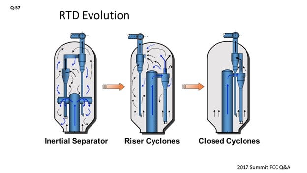
Riser termination systems have evolved from the early days of riser cracking that commonly used inertial separators where the riser hydrocarbon product and catalyst were discharged into the reactor where non-desirable post-riser cracking reactions occurred. The next major advancement was to add efficient catalyst separation devices – such as riser cyclones to the end of risers – to quickly separate the catalyst from the hydrocarbon products. While this terminated that catalytic cracking, it still allowed the hydrocarbons to undergo thermal cracking reactions as they were discharged into the large disengager vessel, which resulted in long hydrocarbon residence times.
Just a little history: In the mid-1980s, Mobil recognized a need to eliminate these undesirable thermal cracking reactions that occurred in disengager and developed the first Advanced Riser Termination System – commonly called ‘closed cyclones’ – where they coupled the riser cyclones directly to the upper cyclones. Mobil pioneered the use of advanced riser termination and installed it in eight of their own units in the late 1980s. In 1990, KBR formed an FCC alliance with Mobil and began licensing the technology. While Mobil’s development and commercialization worked out many of the issues prior to KBR’s involvement, there have been improvements in the technology since then, which I will discuss.
Many of the improvements in KBR’s 27 years of experience have been operational-related. For example, we have been able to reduce startup steam requirements by lowering the required riser cyclone inlet velocity requirement without any negative impact.
One of the keys to a successful startup is to avoid overloading the cyclone system during initial steam circulation. This means making small increases in catalyst circulation and letting things stabilize before making another increase. Once feed is in the unit and cyclone velocities are increased, then the system becomes very stable and resilient.
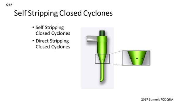
One improvement that has been developed is referred to as ‘self-stripping closed cyclones’ where small holes are placed in the lower cone section of the riser cyclones where the stripping steam flows through. The purpose of this modification is to eliminate the small 2% underflow of hydrocarbon that is normal for a closed cyclone system. This improvement further reduces thermal cracking, thereby increasing the gasoline yield. Another version of this process is referred to as ‘direct stripping’, where external steam is supplied separately to the cone section and the normal cyclone hoods are maintained. This gives the operator flexibility to optimize the cyclone stripping steam.
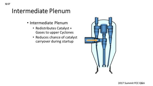
Another change we are implementing on newer projects is to use an intermediate plenum between the riser cyclones and the upper cyclones, as shown in the figure. The main reason for this change is that it allows the catalyst to be redistributed to the upper cyclones and makes the system more resilient to an upset of a primary riser cyclone. Another advantage is that it allows the use of a different number of upper cyclones than that of the riser cyclones. This can have a layout advantage, especially on larger units where we can have two large riser cyclones and maybe four or five upper cyclones. Due to the ability to use smaller upper cyclones, the required vertical space will be reduced as a result of the cyclones being shorter compared to the layout of a system with two large upper cyclones.
MALLER (TechnipFMC Process Technology)
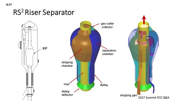
The evolution of our technology at TechnipFMC is similar. We initially had the inertial separator, which had vented gas tubes to the upper reactor section to be close to the reactor cyclone inlets. Now we have a totally closed system. What is shown on the slide is the RS2 (riser separator) technology. One important point I want to make is that the ability to maintain ease of operation during startup, shutdowns, and upsets – without the risk of massive catalyst carryover – is important. With this technology, the diplegs are very large and not prone to flooding. It is essentially an inertial separator, so there is not a high velocity requirement to maintain adequate separation; therefore, there are no emergency steam requirements for startup. If we get enough velocity to transport catalyst, it is enough velocity to achieve good separation. Therefore, the RS2 does not experience any massive catalyst carryover events during startup.
Our recent improvements: We are now learning that we have more units go through turnarounds. Unfortunately, the cycle for these lessons on reliability is every five years when a unit shuts down. We are currently making mechanical and reliability improvements to each situation when we see the requirement. We have made some changes to the slip joint design that allow for the independent thermal expansion of the lower section versus the upper section. We are also working continually with the cyclone vendors to try to improve the overall system efficiency for catalyst collection.
DAVID HUNT [Shell Global Solutions (US) Inc.]
I would like to add that in the FCCs we operate at Shell, as well as at several of our third-party customers, the cyclone technology uses what we call a ‘coke catcher’ which keeps coke from falling into the reactor cyclone dipleg and potentially blocking the dipleg during the run. Other developments in our Shell cyclone system include the use of a vortex stabilizer in the secondary cyclones to control the vortex and avoid dust bowl/dipleg erosion.
ALEX MALLER (TechnipFMC Process Technology)
The primary goal of a modern riser termination system which considers the close coupling of the primary and secondary separating devices is the reduction of residence time and, thus, the minimization of undesirable thermal cracking reactions. This post-riser cracking usually translates to dry gas yield at the expensive of other, more valuable products. By revamping an older type of system to a close-coupled advanced system, we have seen a typical reduction of dry gas yield of about 20% with corresponding increase in liquid product volume.
Another important goal of a modern riser termination system is the efficient separation of catalyst particles from the reactor gasses, implemented with the aim of preventing excessive catalyst accumulation in the main fractionator bottoms circuit. This goal is important for all modes of operation, including startup/shutdown and transient periods. The system we have now is extremely efficient during normal operation, but most notably retains very high levels of efficiency at all times when catalyst is circulating. The primary separator is a positive pressure type, and the diplegs are very large and not prone to flooding. This arrangement ensures that any velocity sufficient to transport catalyst up the riser is enough to achieve adequate separation. No emergency steam is required. No massive catalyst carryover events have occurred on any of our installations.
Our focus for technology improvements in recent years has focused on the reliability, as well as incremental improvements to the above-mentioned primary goals. For reliability, we have updated the design for the slip joint that ties together the upper cyclone portion of the system to the lower termination device. The new slip joint design has proven to be extremely robust without any issues reported on any units.
MATTHEW WOJTOWICZ (Honeywell UOP)
Evolution of UOP’s Vortex Separation Riser Termination Technology
Before evolving to the vortex separation riser termination technology, UOP gained experience with all types of riser termination technology. Since 1983, UOP’s designs for riser termination devices have focused on reducing the post-riser vapor residence time in the reactor vessel. Since many of UOP’s efforts have involved technology upgrades in existing units (revamps), a variety of mechanical systems have been implemented to accommodate the wide variety of existing reactor sizes and styles. All of the UOP designs emphasize operating flexibility and mechanical reliability.
UOP’s current riser termination design incorporates the state-of-the-art vortex separation technology to minimize the vapor passing into the reactor vessel and thereby minimize non-desirable reactions.
In 1995, UOP commercialized the VSS™ (vortex separation system) technology which was specifically designed for higher capacity units with an internal riser while maximizing hydrocarbon containment, operating flexibility, and mechanical reliability. UOP’s VDS™ technology offers the same benefits for units with external risers. The VSS technology has evolved since it was initially commissioned in 1995. These enhancements have further improved hydrocarbon containment, operating flexibility, and mechanical reliability. A few of these enhancements are summarized below.
Hydrocarbon Containment Advantage
Vortex separation technology represents the highest hydrocarbon containment technology available, as it provides more than 99% containment of the hydrocarbon product vapor relative to only 94 to 97% for the next best system (direct-connected cyclone systems). The containment advantage is based on the quantity of hydrocarbon product vapor that is entrained with and adsorbed on the catalyst discharging from the first-stage cyclones. This hydrocarbon is equivalent to as much as 6% of the riser vapor. The hydrocarbon carryunder spends relatively long residence times in the reactor vessel before finally exiting out through pressure equalizing tubes.
The vortex separation technology is designed to eliminate the hydrocarbon flow that exits at the bottom of the conventional riser separation devices, as well as efficiently separate the catalyst from vapor exiting the riser. The top of the stripper and the bottom of VSS chamber are integrated with each other thereby allowing the riser and stripper vapors to be contained. These vapors are prevented from entering the reactor vessel where they can undergo nonselective thermal cracking due to long residence times. The containment advantage of the VSS technology is illustrated in Figure E-1. Since the original implementation in 1995, the design has been tweaked to further improve hydrocarbon containment. The bed level has also been optimized further improving yields.
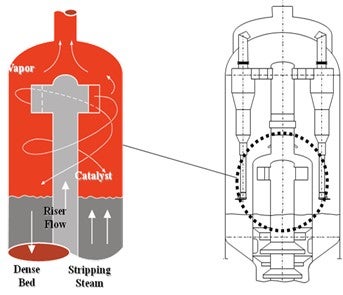
Figure E-1. VSS Hydrocarbon Containment Advantage
The superior hydrocarbon containment performance of the vortex separation technology provides improved yield performance over all competitive systems. The hydrocarbon not contained by the primary separation device undergoes significant nonselective thermal cracking due to long residence times in the reactor vessel. This results in a significant increase of dry gas, as well as major losses of gasoline, LCO (light cycle oil), and overall product olefinicity. Dry gas production – at the expense of the gasoline and LCO production – represents an opportunity loss which limits the profitability of the FCC unit. Additionally, the reduced olefin content of the gasoline will result in a reduction in the octane of final FCC gasoline product. The VSS technology reduces nonselective, post-riser cracking and can help maximize the profitability of the FCC unit through improved gasoline selectivity, improved gasoline octane, and reduced dry gas.
Operability and Reliability Advantage
UOP has significant experience within fluid catalytic cracking technology and has garnered a reputation for designing technologies for maximum operability and reliability. The vortex separation technology offers clear operational advantages over previous generation riser termination devices (RTDs), including ease of startup, turndown flexibility, reduction in reactor coke formation, and reduced incidents of severe erosion of internal components.
During FCC unit startups, operations can experience pressure upsets which quickly send large amounts of catalyst into the reactor vessel. Pressure upsets of this kind are known to quickly overload other RTD designs and send large amounts of catalyst to the main column, causing costly high-catalyst makeup rates and problems in the main column or the main column bottoms product. Conversely, the vortex separation technology can easily handle pressure surges and reduce the risk of catalyst carryover through the use of its unique primary separation design. This operational advantage manifests itself as smoother and more robust operation of the FCC unit during upsets and is relatively more forgiving during unit startups.
Not only does the vortex separation technology offer process and operability advantages, but it also can provide several reliability advantages. Coke formation in a reactor is largely influenced by the reactor technology and appropriate use of steam. The coke produced in the reactor space can build up on the reactor walls or refractory, pressure equalization openings, and other flexible joints, which can lead to either equipment failure or increased maintenance costs. The latest vortex separation technology creates a hydrocarbon-free environment in the dilute phase of the reactor by maximizing riser hydrocarbon containment. Coke has been completely eliminated from the reactor annular space. The vortex separation technology has been used as a process revamp improvement, as well as a technology upgrade to address coke formation.
UOP’s design methods include several considerations and features which have dramatically reduced the incidents of severe erosion of internal components over time. Internals are designed with appropriate orientation and velocities to minimize erosion potential in critical areas such as cyclone inlets. UOP also specifies proven refractory- and abrasion-resistant lining materials in these areas which often survive a run with only small sections requiring repair. Utilizing these design methods, the vortex separation technology offers improved mechanical reliability of the reactor internals, improved unit availability, and reduced maintenance costs over the next best RTD alternative. Also contributing to the high mechanical reliability of the technology is the fact that over 95% of the catalyst separation occurs in the low-velocity VSS chamber, meaning that less than 5% of the catalyst will enter the higher velocity cyclones. There are multiple refiners with UOP’s latest VSS technology who achieve 99+% onstream efficiency with minimal maintenance required to internals following a campaign of more than five years.
FOOTE (CHS Inc.)
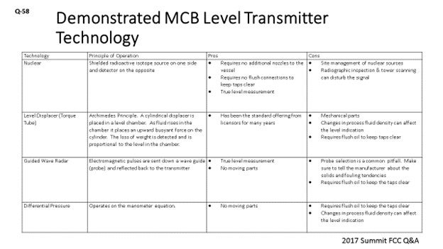
I prepared a few tables about technology and the principle of operation pros and cons of each of the demonstrated level of technologies and main column bottoms level transmitter. Again, it goes without saying that accurate measurement of the main column bottoms level is essential for reliability and safety. First, what I will talk about is nuclear. One of the benefits of nuclear technology is that it does not require any additional nozzles in the vessels. So, if you are looking for redundancy and do not want to go through the expense of installing a nozzle, this is a good option for you. Nuclear also does not require flush connections. Every bit of HCO (heavy cycle oil) flush you put back into the bottom circuit will affect your fractionation, so minimizing HCO flush is a big deal. Nuclear technology also gives you a true level measurement. The drawbacks to nuclear are obviously site management and nuclear sources; but likely, you already have these in your refineries. RT (radiographic testing) inspection and tower scanning can mess up your level indication. Just make sure people are communicating when they are doing x-rays in their work areas.
The next technology is the torque tube. Basically, it is a cylinder that operates inside of a chamber where the fluid exerts a buoyant force on the cylinder. The difference in the weight is detected and corresponds to a level. Torque tube technology has been the standard offering from licensors for years now. The drawbacks to it are that it is a little mechanical; not terribly mechanical, but there are pieces that can fail on it. It also changes in process. Fluid density on startup, shutdown, and malfunction can affect the level measurement. The torque tube also requires flush oil.
The third technology is guided-wave radar. Again, it gives you a true level measurement and has no moving parts. The common pitfall here is probe selection. Make sure your manufacturer knows that there is the potential for solids in these circuits and that he/she gives you the right type of probe. Sometimes the probes can be too tight, and you can plug them up. Guided-wave radar also requires flush oil to keep the taps operational.
The last technology is pressure differential, which is very similar to torque tube. It is a proven technology; but again, it does not give you a true level if you have gasoil, say, at the bottom of the main column on startup.
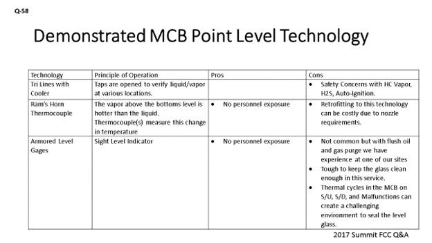
The next slide gives us the Point Level Technology. So, in addition to level transmitters, we also want to have point level indication. For years, the standard from licensors has been the try lines with the cooler. Obviously, the taps are open and you either have vapor or liquid there. The try line taps provide you with the means of telling you where the level is within the column. Obviously, there are safety concerns with try lines because you have H2S vapor and auto-ignition possibilities.
The second technology – Ram’s Horn Thermocouple – is one that I am not sure has been commercially demonstrated in an FCC unit but which I think has been used in crude and in vacuum columns. Basically, the sub-cooled liquid is detected as the level goes up. There is no personnel exposure here. Retrofitting this technology can be costly, because it does require one nozzle for the thermocouple and another one for the ram’s horn drain that goes down below.
Armored-level gauges have also been used. This equipment is not very commonly chosen. With purging, you can keep the glasses clean, although it is tough to do. Also, because of the thermal cycles you run on the startup, shutdown, or malfunction, keeping that glass sealed can be challenging. So, there are some challenges with that technology.
Regardless of the technology we are using, redundancy is important. Right? I think it is best to use two different types of technology, if possible. However, Best Practice is to employ two level transmitters with the selector switch from the main column bottoms level control. For displacers, guided-wave radar, dP transmitters, and redundant transmitters need their own individual taps. So, do not try to put them on one set of vessel taps, because that is a single point of failure. For point level measurement, at least two points should be measured for high and low levels.
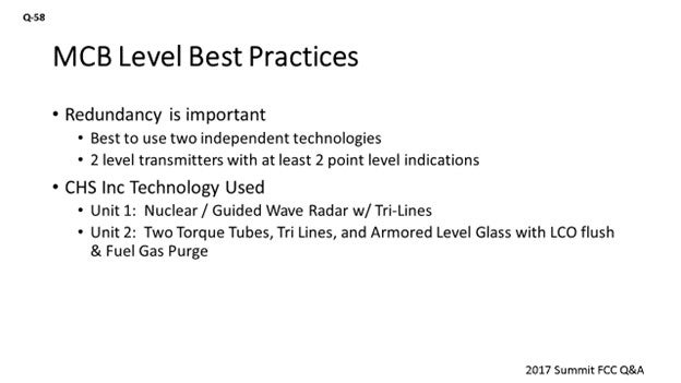
At CHS, we operate our Laurel, Montana FCC. We use nuclear and a guided-wave radar with flush oil, and we use try lines for point level indication. We are strongly considering going to the ram’s horn thermocouples because of safety concerns at that FCC. At our McPherson refinery, we use two redundant level displacers and two armored gauge glasses that have LCO flush and fuel gas flush or fuel gas purge as well. We also have tried lines at McPherson.
MALLER (TechnipFMC Process Technology)
The TechnipFMC standard is a diaphragm-type pressure differential level instrument. We use continuous HCO flushing. We would like to see multiple instruments there for redundancy. I would go as far as to say that three separate instruments should be used. That way, you have the chance that two of them read the same, rather than having to discern which is correct with only two different readings. Also, I like to see a local gauge for field verification, which I have seen successfully applied via magnetic-type float gauges in service.
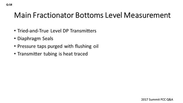
TRAGESSER (KBR)
KBR’s normal practice is to offer a tried-and-true method that uses simple level transmitters for main fractionator bottoms. Both level transmitters are pressure differential types and share the nozzles at the vessel. Multiple transmitters are provided for improved reliability. The board operator has the option to switch between the two measurements.
Both level transmitters use a diaphragm seal to prevent slurry and solids from getting into the transmitter.
The main fractionator measurement nozzles at fractionator shell are purged. We use fuel gas to purge the low pressure tap and flushing oil to purge the high-pressure tap. The tubing for the transmitters is electric or steam-traced to minimize the potential for blockage if the purge is lost.
MELVIN LARSON (KBC Advanced Technologies, Inc.)
How far up do you take your top tap on your level transmitter?
MALLER (TechnipFMC Process Technology)
Typically, we have a reduced diameter boot at the bottom of the fractionator and we take the top tap at the top of that area. We do not take it up into the flash zone.
DARIN FOOTE (CHS Inc.)
The following tables list the demonstrated technologies to reliably measure main column bottoms (MCB) level. Regardless of the technology used, it is important to have redundant level indication. The Best Practice is to employ two level transmitters with a selector switch for MCB level control. For displacers, guided-wave radar, and dP level transmitters, redundant transmitters should be on independent vessel taps. There are benefits to having two different level technologies employed. For point level measurement, at least two points should be measured for high and low levels.
Table 1. Level Technologies for Main Column Bottoms Level Transmitters
|
TECHNOLOGY |
PRINCIPLE OF OPERATION |
PROS |
CONS |
|
Nuclear |
Shielded radioactive isotope source on one side and detector on the opposite |
|
|
|
Level Displacer (Torque Tube) |
Archimedes Principle: A cylindrical displacer is placed in a level chamber. As fluid rises in the chamber, it places an upward buoyant force on the cylinder. The loss of weight is detected and is proportional to the level in the chamber. |
|
|
|
Guided-Wave Radar |
Electromagnetic pulses are sent down a wave guide (probe) and reflected back to the transmitter. |
|
|
|
Pressure differential |
Operates on the manometer equation. |
|
|
Table 2. Demonstrated Methods for Point Level Indication in the Main Fractionator Bottoms
|
TECHNOLOGY |
PRINCIPLE OF OPERATION |
PROS |
CONS |
|
Try Lines with Cooler |
Taps are opened to verify liquid/vapor at various locations. |
|
|
|
Ram’s Horn Thermocouple |
The vapor above the bottoms level is hotter than the liquid. Thermocouple(s) measures this change in temperature. |
|
|
|
Armored Level Gages |
Sight Level Indicator |
|
|
At our Laurel, Montana FCC, we use nuclear and guided-wave radar for redundant indication and try lines for point indication. We are strongly considering getting rid of our try lines and replacing them with ram’s horn thermocouples due to safety concerns. In our McPherson, Kansas FCC, we use redundant level displacers and two armored gage glasses for point indication.
ALEX MALLER (TechnipFMC Process Technology)
We use diaphragm-type pressure differential level instruments with continuous HCO flushing oil provided to the connection at the vessel. Multiple instruments are typically used to provide redundancy and some confidence in the readings. A magnetic-type float gauge can also be provided for verification in the field, but it should be insulated, steam-traced, and provided with continuous flushing. With these arrangements, level measurement at the main fractionator bottoms is not typically a big issue. Some units have applied nuclear-type instruments successfully for this service, but it is not our standard to do so.