
Networking Reception: Regional Networks and Emerging Leaders — Invite Only
A networking event for emerging safety professionals and All-Regions group. Invite only.
Sponsored by: Health and Safety Council (HASC)
Sponsored by: Health and Safety Council (HASC)
Session Start End
-
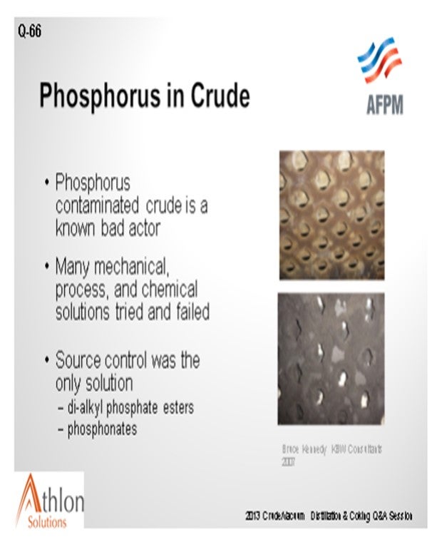
Question 66: What strategies should be considered to adjust for phosphorous in crude oil to protect downstream catalyst and processing units?
HODGES (Athlon Solutions)
Extensive work was done with Western Canadian refineries in the late 2000s to investigate and solve this problem, including adjusting desalter pH to extract phosphorous in the desalter brine, adding a phosphorous removal chemistry, changing the trays in the crude tower to reduce fouling susceptibility, solvent-washing the deposit to avoid long cleanouts and shutdowns, and adjusting process temperatures. These were not met with great success. This was a consortium effort where many operators tried many approaches. What they determined was that the only solution was source control from the upstream additives used in crude production.
When we started the panel discussion this morning, I mentioned that I have been in the special chemical industry for over 30 years. Eighty percent of that has been the in downstream operations, but I did spend a good part of the time in the upstream. What was very amazing to me was seeing everything that is put into the wells when they are completed and producing. The work that was done in Canada identified that one of the primary sources of the phosphorus they were seeing was volatile dialkyl phosphate esters which are used in gel fracs. Fracking is a high-pressure pumping operation that is used to open formations when wells are completed prior to production.
Another common use of chemicals during oil well production is for scale control in the near well bore area, production tubing, and associated equipment. Commonly, this involves an application technique known as a scale squeeze. During a scale squeeze, well production is stopped and then phosphonates are pressure pushed down the production tubing and into the reservoir. After a soak period, the well is returned to production. These phosphonates slowly desorb off the reservoir rock as the oil and water are produced and prevent scale buildup in the system. This is effective in terms of preventing well scaling problems but also adds phosphorous to your crude. Compounding the “contamination” problem, scale squeeze frequency greatly accelerates over the life of the well as it waters out. The implication here is that early on in the life of a particular reservoir, there will be no scale treatment and therefore no phosphorus contamination; but as time goes on, it may ramp up very sharply. There are many classic examples of this in the North Sea.
I encourage everyone to visit the CCQTA website where there is a wealth of information on the work done by the member organizations.
In addition to the source control, if running a naphthenic high TAN crude, many people will apply a phosphorous-based naphthenic acid inhibitor. Make certain that your process chemical supplier has the capability to model the distribution of the phosphorous in your system and to assure good phosphorous management practices.
SHENKLE (Flint Hills Resources, Ltd.)
We have not really seen a change in phosphorous into the refinery and therefore have not made any crude slate changes. We have received confirmation from our last crude turnaround that there was no evidence of phosphorus in the jet section of the tower. There are some detailed responses in the Hydroprocessing Q&A for downstream effects on catalyst.
PRIBNOW (CITGO Petroleum Corporation)
Even though we had the fouling in those trays, we have not attributed any mid-barrel hydrotreating catalyst deactivation at this time. The phosphorous compounds probably all ended up on the trays. I know that desalter washwater acidification has been mentioned a couple of times. We are considering performing a trial to determine if we can remove the phosphorous components and direct them to the desalter brine. That is a trial we are pursuing to see if we can take care of that problem.
ALLEN KAISER (Delek Refining, Ltd.)
How much phosphorous is too much? Where is the breakpoint between it being a minor irritant and a major problem?
HODGES (Athlon Solutions)
I would not say that is well-known by refiners. I think it is very much dependent upon the type of phosphorous compound that is being used in upstream scale control, which can be further acerbated if you are applying phosphorous-based naphthenic acid inhibitors to your system as well. Because of the wide variety of the nature of the phosphorous compounds that are used in the upstream, you can and do get different chemistries and different concentrations. That will change from crude type to crude type and over the age of the field, and as the producer changes chemical suppliers. Unfortunately, there is not a very clear answer to that question. Proper management of phosphorus, in our estimation, is best worked out with your chemical supplier who can help you characterize crude, monitor the fouling propensity, and also investigate alternate methods of removal.
Going back to some of the previous answers, in the case of the Western Canadian refineries, they actually put a specification on the pipeline in the transport of the crude where they had a phosphorus spec. So, in that case, the producers of the oil were forced to comply by not putting phosphorous compounds into the oil. It is a very unique situation; because in most cases, refiners cannot greatly influence producers in terms of what they do and do not use as long as they meet sales specifications. Phosphorus is not a sales specification on crude. In the case of the Western Canadian refiners, changing the phosphorus spec on the pipeline was the only solution they found to control the huge issues they had running phosphorus contaminated crude.
XIOMARA PRICE (GE Water & Process Technologies)
The recommendation from the CCTQA was less than 0.5 ppm of phosphorous in the feed. However, there are other types of crudes I see that now create problems with phosphorous fouling in the tower. You have to be careful and look at it. It is volatile phosphorous; so, unless you are injecting it in there, you have to measure it properly; not total phosphorous, but volatile phosphorus.
UNIDENTIFIED SPEAKER (Shell Global Solutions U.S.)
I heard you mention other crudes, but is there evidence of more phosphorous contamination in tight oils specifically, other than Canadian crudes?
HODGES (Athlon Solutions)
I think you are asking are specific pipelines more notorious for transporting phosphorous-containing crude. Again, there is not a pat answer for that, particularly with all the advent of the tight oil in the U.S. It is a completely different chemical landscape upstream today than it was five years ago. The types and amounts of chemicals that producers are putting into their well, both when they complete it and during production, have not been seen before. I can speak from firsthand knowledge that there is a tremendous amount of focus by the producers to use materials that help them operate more reliably and efficiently, which is not necessarily in the best interest of the refiner.
I do not think there is an easy answer to this problem. Obviously, if you could put a phosphorous specification in place, it will help you manage this. But over the life of the field, even a specific crude type will increase in phosphorous content because of the increase in scale squeeze frequencies that typically take place over time. So it is a challenging question. I encourage you to work with your chemical supplier to understand and better characterize the crudes coming in and have him/her provide some additional surveillance for your particular operation.
BOB SHENKLE (Flint Hills Resources, LP)
At FHR, we have not witnessed a substantial increase in phosphorus. Within the Hydroprocessing Q&A session, we present a detailed response regarding the expected impact of phosphorus on hydrotreater catalyst.
SAM LORDO (Nalco Champion Energy Services)
Nalco Champion has developed a phosphorous sequestering agent. In the lab and in limited field trials, this product has been shown to react with free phosphate-ester compounds or derivatives to form a thermally stable complex and move the phosphorous out of the vacuum bottoms of the crude unit.
Year
2013
Process
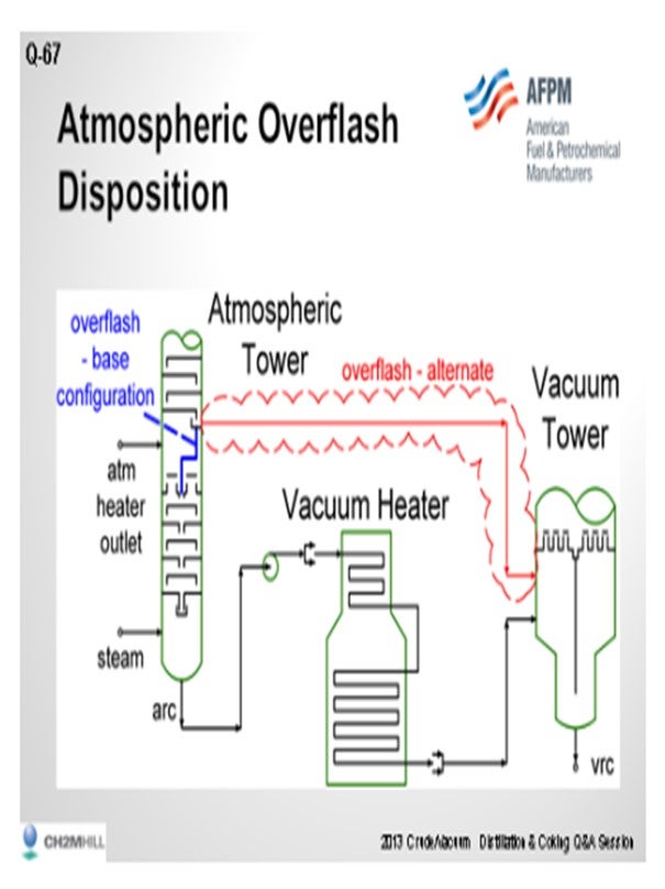
Question 67: When heat input is limited at the vacuum heater, what are the issues with bypassing crude tower over-flash around this heater?
SLOLEY (CH2M Hill)
For this answer, I am going to define crude tower over-flash as liquid collected on a collector tray above the flash zone at the atmospheric crude column. This may be either a total collector tray or some form of active tray. This liquid contains a mixture of entrainment from the flash zone and distillate from the wash section. The normal disposition is to send the liquid inside the tower down to the stripping section. The lighter end of the material is stripped and recovered in the atmospheric tower and the heavier material ends up as atmospheric tower bottoms. So the overflash stream is distinct from the atmospheric tower bottoms. It has not been stripped. It contains light material often down into the kerosene boiling range. Depending on the vacuum tower configuration, the light material can significantly load the vacuum system.
Dry vacuum towers (that is, vacuum towers with no pre-condenser in front of the ejector) tend to have small vacuum systems. The additional load from the unstripped material can significantly raise the vacuum ejector suction pressure. The vacuum towers with large ejectors or with pre-condensers tend to be more resistant to small changes in the load to the light material to the ejector. Conceptually, sending this stream directly to the vacuum tower has somewhat the same effects as damage to the stripping tray section. The query to the person who asked the question would be: Why not just bypass some of the atmospheric tower bottom if you are going to do this? Really, it will have the same effects on unloading the vacuum heater duty and will have a smaller effect on the vacuum system.
Now if the vacuum system can handle a light material, bypassing does gain you some yield on the gas oil in that stream. Nevertheless, you can get flashed on quenching if you mix that material with the vacuum heater outlet. The Best Practice would be to send this to the vacuum tower and let it flash without mixing with the material coming from the vacuum heater.
One other observation: In the case with a packed atmospheric tower wash section that operates properly, the total over-flash rate is very low compared to the crude. The distillate content is also low. Except for the vacuum system loading, the effect of bypassing the over-flash would be so small it would be nearly unnoticeable.
Trayed atmospheric towers require much higher liquid rates to work properly, so the over-flash rates may be much higher and give you a noticeable yield change with different over-flash dispositions. The atmospheric tower configuration will also affect the benefit of the changes seen. Over-flash from the atmospheric tower, with diesel as the lowest product, will have more light material, and that will cause a higher load change on the vacuum system.
Year
2013
Process
Question 68: For those refiners seeing an increase in vacuum overhead chloride concentration at constant desalted crude salt content, what are the consequences and how can they be controlled?
SLOLEY (CH2M Hill)
First, verify the chlorides found in the hot well water. Could the chlorides be from leaks from the vacuum system condenser cooling water? A hardness test will quickly identify water system leaks. Essentially, getting a high chloride concentration in the vacuum overhead at a constant salt content in the desalted crude implies either a change in the chloride type or in the operating conditions leading to more chloride hydrolysis. Enough water is present in most vacuum systems that the chloride concentration in the water condensate is low. Chloride corrosion issues in the vacuum system are relatively rare.
Some refiners have seen chloride concentrations in the vapor phase in the vacuum tower high enough that ammonium chloride directly deposits from the vapor phase. The problems from this had included near complete plugging of wire mesh mist eliminators installed in the tower above the LVGO (light vacuum gas oil) pumparound distributor and in-plugging of the LVGO drawer nozzle with solid ammonium chloride plugs.
Underdeposit corrosion has also occurred on the LVGO collector trays. In other units, ppm levels of chloride had been found in vacuum diesel which can cause downstream problems in hydrotreating end products. The most effective way to deal with chlorides is to remove them at the desalter. If they cannot be removed at the desalter, operating changes to the reduced vacuum heating severity are the most effective means of reducing the number of chlorides hydrolyzed upstream with a vacuum tower.
Vacuum tower yield economics tend to overwhelm any advantages of lower heater temperatures being used to reduce chlorides in the vacuum tower. As long as the vacuum heater, vacuum tower, and vacuum systems have the capability to handle the load, maximize heater velocity steam. This lowers the oil film temperature and shortens residence time. This will minimize chloride hydrolysis. Since these changes also improve yields and product quality—at a constant yield—they should be done in any case.
PRIBNOW (CITGO Petroleum Corporation)
I agree with what Andrew said. The overhead chloride concentrations will cause corrosion within the tower and the overhead system. We have observed some different corrosion mechanisms in the outlet piping of our ejectors, as well as the shells and the condensers, to the point that we even holed-through one of the elbows. You can have some corrosion issues in that overhead.
One of our vacuum towers is a dry tower. It has a pre-condenser. Andrew mentioned these ammonium chloride salts that come out. We will see them laying down in the ODs (outside diameter) of the tubes at this condenser. They will create higher differential pressure and ultimately degrade lift in the vacuum tower and affect the gas oil cutpoint. We found that doing a heat-up of some sort will move this ‘goo’, as we call it, or ammonium chloride salts. It will move the material right off those tubes and allow you to continue operation without a shutdown and without having to clean the bundle. If we have to clean the bundle, we will need to get it wet. We have experienced corrosion from the water/ammonium chlorides and upgraded metallurgy to alleviate.
The higher chloride concentrations can be a result of many causes. Each has its own method of remediation. Injecting wild streams directly to the vacuum tower may be a likely cause.
Organic chlorides: I think Andrew mentioned that the chlorides will travel out of the bottom of the atmospheric tower and hydrolyze in the heater, going overhead in the vacuum tower. Some halogens, which we call Smarties, can be measured as chlorides in lab tests. These are tightly bound asphaltene salt crystals. They are harder to get out in the desalter and are hydrolyzed in the heater, eventually coming out in the overhead system.
Aside from troubleshooting some of the above-mentioned items to improve desalting, as Andrew mentioned, we optimize our water and raise our ∆P and mix valves to get better mixing to break apart the Smarties. Acidification of the washwater will remove calcium and magnesium salts. And then, always maintain that minimum salt point temperature on the top of your vacuum tower. Salt point should be calculated. We like to be conservatively 20°F over the salt point. Do not allow the overhead temperature to get below the salt point or, as was mentioned, salting of the LVGO section and plugging will occur. Try and keep the salts in the overhead where chemistries can treat.
VILAS LONAKADI (Foster Wheeler USA Corporation)
Of course, the chloride is the inorganic versus the organic, though organic ones are saline. In one vacuum unit, I have seen temperatures increased so high that the design went from a normal system using just ejector, to having to install a pre-condenser.
DENNIS HAYNES (Nalco Champion Energy Services)
I want to point out a few additional causes. There was some research that originally started in the 1930s. When I was working over in Japan in the 1990s, I reviewed some material done by the Japan Petroleum Institute on Middle Eastern crudes where they reviewed various blends. They noticed that depending upon which crudes they were blending, they were able to get different hydrolysis rates. Subsequently, more modern research was done by others; specifically, regarding naphthenic acid-bearing crude blends. It was noticed that as the naphthenic acid content of the blend was directionally increased, there was more hydrolysis of the calcium and the sodium chloride. This may actually push some of the hydrolysis further downstream. So, I want to point that out as an additional cause. As far as the solution to the hydrolysis, it gets back to improved desalting caustic utilization and neutralization, if the chlorides make it to the overhead system.
HAROLD EGGERT (Athlon Solutions)
Before going on too much with the chloride quest, I will say that we see unexplained, elevated chloride levels a couple of times a year; so, it is important to get a sample of your overhead water and run a hardness test on it. It takes a very small cooling tower exchanger leak to actually drive the chlorides up in the overhead. That is often simple. So have your vendor start adding that to the test, not only in the vacuum tower but also in the crude overhead. Do not be fooled into thinking it is just cooling water. It is innocuous. Cooling water is saturated with oxygen. We have had discussions here today about all the evils of oxygen. You can have oxygen coming into the hot well and move that water back to the desalter. It just sets up a vicious cycle. It is a quick, easy task. Have your vendors run hardness on all the overhead water samples, assuming there is a cooling water exchanger in their system.
SIMON ARENDS (Marathon Petroleum Corporation)
Can you give more details on asphaltene hydrolysis? At Galveston Bay, we have seen fouling of our vacuum overhead system with this gooey asphaltenic-looking material. How do you mitigate that? How do you clean it?
SLOLEY (CH2M Hill)
It comes back to the question of phosphorus. We had a discussion earlier this morning about the phosphorus going with the kerosene. Depending upon the level of effectiveness of your stripping section in the atmospheric column, you will end up with kerosene boiling-range material in the overhead of the vacuum system. There have been at least a couple of incidents where phosphorous in the overhead of vacuum systems makes deposits when it mixed with hydrocarbon carried over from the vacuum tower. It is often difficult to be prove that this might be happening, but it is one potential cause of vacuum system problems.
PRIBNOW (CITGO Petroleum Corporation)
Right now, I believe that all we do is improve that desalter efficiency. We try to sheer in the mix valve and get better mixing in the desalter. Tower delivery temperature steam-to-crude ratio can be evaluated. You said that the heater outlets can be decreased so that you do not hydrolyze. And then, like we said, we are going to try the acidification process and see if that can break down the tightly bound asphaltenes.
HODGES (Athlon Solutions)
I want to add that the mixing is a key component, as Phil mentioned. In several studies we have done, we have learned that adding as much water as you can into the crude charge pump suction is the only way to effectively contact and remove the interstitial salt coming in that is bound up with the asphaltene compounds.
GLENN SCATTERGOOD (Nalco Champion Energy Services)
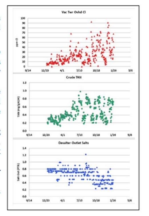
The observed increased in vacuum tower overhead chlorides, in some cases, can be related to the increase in TAN crudes. This phenomenon has been observed since the 1930s and was re-demonstrated recently by several research groups. The figure shows an example of this phenomenon.
Control of an increase in chloride in the vacuum tower overhead is similar to those used to control chlorides in a crude overhead tower:
a) Add caustic to suppress hydrolysis. This will help minimize some of the calcium chloride that was not hydrolyzed in the crude furnace from readily hydrolyzing.
b) Accurate monitoring of vacuum overhead chloride and proper neutralizer injection dosage is critical to control corrosion from this higher chloride concentration.
c) Improve CaCl2 removal by improving desalting (washwater rate and location, mix valve, demulsifier type, temperature, crude tank treatment, etc.).
d) Improve metallurgy of the vacuum tower overhead.
e) Reduce the amount of the high TAN crude that is causing the increase in hydrolysis.
DENNIS HAYNES (Nalco Champion Energy Services)
Through the years, various studies have been done which show that crude composition can impact the hydrolysis of salts and increase hydrogen chloride to downstream distillation columns. The consequences are increased corrosion rates and requirements for corrosion control technologies (caustic, neutralizer, filmer, metallurgy changes, etc.). The best way to deal with incoming chloride is by removal via desalting, where possible, and then using a caustic (if the unit has the capabilities to apply it). Surrounding this discussion is the uncertainty of undesaltable chlorides or chlorides coming in with the crude that are in a form not removable by extraction (discussed in various industry publications and forums). In the case of undesaltable chlorides, the control becomes blending down the low-quality crude source and using washwater, neutralizer, and filmer where appropriate.
PHILIP THORNTHWAITE (Nalco Champion Energy Services)
The consequence of increased chlorides in the vacuum unit is that it increases the risk of overhead corrosion in the pre-condenser (if present) and in the condensed water after each ejector stage. This will require a subsequent increase in neutralizer and additional monitoring to maintain corrosion rates at acceptable levels.
An additional consequence is that in particular cases where there are high levels of ammonia or possibly tramp amines present, the elevated chloride levels significantly increase the risk of salt formation inside the vacuum tower and upper pumparounds. Once packed beds and pumparounds begin to foul, the fractionation efficiency can quickly deteriorate and ultimately lead to an unplanned shutdown to allow cleaning of the unit.
Year
2013
Process
Question 69: What are some of the advantages and challenges in processing FCC slurry in a vacuum tower along with conventional atmospheric residue streams?
SLOLEY (CH2M Hill)
If you feed FCC slurry to the vacuum unit, the major benefit is recovery of diesel range material. High temperature limits in the bottom of the heavy cycle oil slurry fractionation system limit diesel recovery from slurry. Typical limits in this section in the FCC are 720°F, or 382°C; above that, coking starts to be a major issue. Significant diesel is still present at this condition. Diesel content of the slurry varies from 10 to 12% at a minimum, but many units run much higher. Industry average is in the range of 14 to 15% of the slurry.
Processing the slurry in a separate vacuum flasher is one method of recovering this diesel. The vacuum flasher typically suffers from solids deposit from the catalyst present. Processing slurry in the crude vacuum tower allows for some recovery of the diesel, and that implies that you have a diesel recovery section in the vacuum tower. However, it puts the FCC catalyst in the vacuum residue. As long as the solids in the vacuum residue do not get too high, this may be acceptable.
Most refiners processing FCC slurry in the vacuum unit produce asphalt as the vacuum tower bottoms product. The largest problem with slurry processing is that the slurry is a reactive product that is not going to a stable reactive equilibrium. High temperature plus the reactive slurry components tend to cross-link and see higher fouling rates in the vacuum residue circuit. Keeping the slurry percentage low and quenching in the vacuum tower bottoms to keep the temperature below 700°F, or 371°C, helps reduce fouling rates in the vacuum residue exchanges.
SRIVATSAN (Foster Wheeler USA Corporation)
We see limited advantage in processing FCC slurry in a vacuum tower. However, as Andrew mentioned, in some cases a dedicated vacuum flasher to recover the gas oil fraction could be beneficial. FCC slurry has a distillation range similar to HVGO (heavy vacuum gas oil), but it is inferior in properties compared to straight-run material, making it more difficult to hydrotreat.
A much more common option of disposing the FCC slurry oil is to introduce it as feed to the delayed coking unit. A number of discussions have taken place in previous Q&A forums on how much of the slurry oil can be introduced into the delayed coker. We normally recommend a maximum limit of 10%. Depending on the coker unit design, though, you may have to cut back on your vacuum residue feed rate. Only a small portion of slurry oil converts to coke; most of it just goes for a ride in the coke drum and ends up with the HCGO (heavy coker gas oil) fraction. If this HCGO is sent directly to the FCC without be hydrotreated, it will build a recycle loop that is difficult to handle. Also, if the coke drums are velocity-limited as opposed to coke-make limited, the addition of slurry oil, while still retaining residue capacity, could lead to excess velocity in the coke drum which may result in carryover to the fractionator.
SIMON ARENDS (Marathon Petroleum Corporation)
Are there any concerns about fouling with the catalyst or on the vacuum tower exchangers? Is it filtered or not filtered?
SLOLEY (CH2M Hill)
There are some concerns on coking. Normally, the content of slurry is restricted to such a low percent (less than 10%) that the additional solids do not present a major problem. Vacuum residue itself is not the easiest stream to deal with, and reprocessing slurry does not make the operation easier. But if the slurry content is low enough, it is not a catastrophic increase in the severity in the operation on fouling in most units.
VILAS LONAKADI (Foster Wheeler USA Corporation)
Andrew, you mentioned that you will be putting the slurry into the vacuum tower itself, right? If you do that in the main vacuum unit, the slurry will likely contain solids. Most of the transfer lines and velocities there are at the sonic velocities. So the catalyst and that velocity are going to these internals. Have you seen any kind of erosion which can happen to these internals and damage them?
SLOLEY (CH2M Hill)
There has been evidence of erosion. It is clear it is not a huge issue, but it has to be managed and tracked. Absolutely, there has been erosion.
XIOMARA PRICE (GE Water & Process Technologies)
I have a question about processing SCC (stress corrosion cracking) slurry in the vacuum tower. It is my understanding that the recommended wash oil rate is 0.3 to 0.5 gallons per minute per square foot for that tower. So if you are going to process slurry oil that has higher amounts of contaminants through there, do you recommend that they not change to help with the fouling?
SLOLEY (CH2M Hill)
There is some difference of opinion about that number, but I think the two issues are separate. The presence of slurry does not change what packing wetting rates need to be in the wash section.
JOHN HUGGINS (Huggins & Associates)
I want to emphasize the point made a moment ago about yields in a vacuum tower. That slurry is predominantly gas oil. So, if it is put back to the vacuum tower, it will predominantly recycle back to a catalytic cracker, if that is where gas oil goes in that unit. If that is the situation, why not recycle the slurry in the catalytic cracker and recycle the HCO (heavy cycle oil)? It is usually a bad economic decision because you can make more money by running virgin stocks through the catalytic cracker.
SRINI SRIVATSAN (Foster Wheeler USA Corporation)
We see limited advantages for processing FCC slurry in a vacuum tower. However, a dedicated vacuum flasher to recover the gas oil portion could be beneficial in some cases. FCC slurry has a distillation range similar to HVGO, but the properties are inferior (cetane, sulfur, and nitrogen, two-ring aromatics, etc.) compared to straight-run (SR) material, making it more difficult to hydrotreat. A more common option of disposing FCC slurry is to introduce it as feed to the delayed coking unit (DCU). We typically limit this amount to approximately 10% of feed; and depending on the limitations of the coking unit, you may have to cut back on vacuum residue (VR) feed rate. Since only a small portion of the FCC slurry/decant oil converts to coke, the remaining portion goes through the coker along with the rest of the cracked VR and mostly ends up with the HCGO. If the HCGO is sent directly to the FCC without hydrotreating, this may create a recycle stream that could become difficult to handle due to buildup of refractory type material. If the coke drums are velocity-limited (as opposed to coke-limited), the addition of slurry oil, while still retaining residue capacity throughput, could lead to excess velocity issues in the coke drums.
CHRIS STEVES (Norton Engineering)
Care must be taken if processing FCC slurry in a vacuum tower with atmospheric residue. In some cases, the condensed asphaltenes present in the FCC slurry oil may precipitate when mixed with the more paraffinic atmospheric residue, leading to fouling and plugging problems.
Year
2013
Process

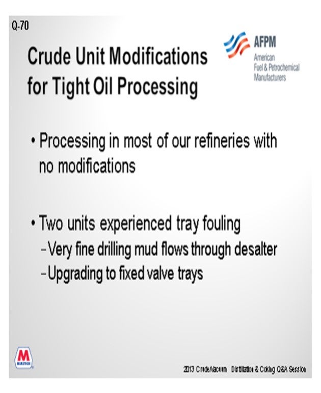
Question 70: What are the key areas to target when contemplating crude unit modifications to enable effective tight oil processing? In addition to these modifications, what other problem areas become evident once the actual processing begins?
HERLEVICH (Marathon Petroleum Corporation)
We run tight oil in six of our seven plants, and it is mixed in the basket of the other 10 to 20 crudes normally processed. Tight oils are not the predominant crude in most places, so we have not needed many modifications. In two instances, we did have tray fouling from drilling mud; so, we installed low fouling trays.
We have projects underway to increase the amount of tight oil received at two plants. The general theme is to install equipment to knock out water, a new pre-splitter, and heat exchange. One of the configurations will employ a pre-splitter for just the tight oils. We will take the overhead into the naphtha circuit and the bottoms to the desalter. One refinery also requires a gas plant expansion to process the incremental light ends.
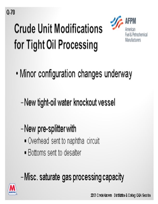
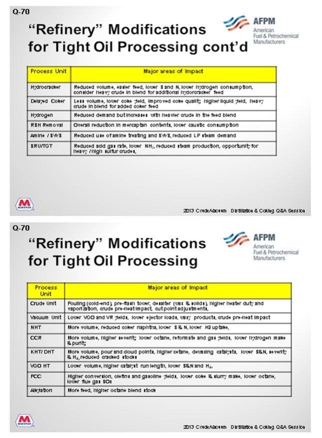
The next two slides were prepared with a larger question in mind: What happens directionally on all the units in the refinery when processing tight oils? I will not go over these slides right now because there is quite a bit of detail on them. The second slide is just the other half of the plant.
HODGES (Athlon Solutions)
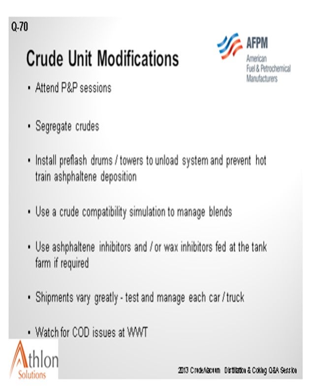
Needless to say, there have been some interesting challenges discovered over the past several years of the running and processing of tight oils. I would like to offer another plug for the P&P sessions later on. Please check your program. There are two P&Ps that specifically address tight oil, and there will be a lot more information presented.
The biggest challenges really have to do with the unique composition of each of these tight oil's formation and the huge variation within a given field from cargo to the next. Often, tight oils are very paraffinic and have significant naphtha yields and very little resid production. If your normal slate is heavy blends, then your light ends processing ability might be inadequate to handle the higher naphtha yields.
Additionally, you might be forced to process blends of tight oils and heavy crude just to keep your coker running. Blending various crudes to meet the distillation profile, though, can often create compatibility issues with forced asphaltene precipitation. Some refiners, as was discussed earlier, have segregated crudes and tankage, added asphaltene inhibitors to the raw crude, and installed pre-flash drums or towers to reduce the light ends content in the hot pre-heat train. Less paraffins in the hot train, like C5 and lighter will induce asphaltene precipitation in the hot train.
Wax precipitation in the cold train has been observed as well. Wax inhibitors fed to the crude tankage or to the transportation of the crude can be used to address very severe issues. It is a good practice to use a simulation program to predict crude incompatibility and wax issues and then adjust your blends, if possible, prior to relying on chemical additives.
Since the gathering and distribution system for tight oils is still in its infancy, there is a significant amount of variation in the crudes that reach the market via trucks and railcars. I discussed this a few questions back as well. This often brings about huge variability in each of the trucks or railcars, depending upon which ranch it was produced on, and this fact demands that you develop a well-considered sampling testing and segregation plan. These shipments often require higher usages of H2S scavengers, which could create issues with tower fouling and increased COD (chemical oxygen demand) in the wastewater plant.
SRINI SRIVATSAN (Foster Wheeler USA Corporation)
A good overview of problems when processing shale oil was presented by C. Sandu and B. Wright of Baker Hughes in the July 2013 issue of Hydrocarbon Processing. Some of the problems include:
• Corrosion in crude units due to addition of amine-based products in upstream production;
• Problems due to incompatibility of asphaltenic crudes and paraffinic shale oils affecting all areas from tank farm to CDU. Concerns are in tankage, crude pre-heat, desalter operation (dark brine with potential high COD), heater fouling in both VDU and DCU, and exchanger fouling in both the cold and hot trains;
• Problems due to high solids loading affecting desalter operation; and,
• The quality of the finished products.
GREG SAVAGE (Nalco Champion Energy Services)
Refiners processing high levels of tight oil, 75% and greater, often are outside of design as tight oil contains very little gas and residual oil content. As a result, several refiners have experienced major shifts in the heat balance and velocity profiles on the pre-heat train. Evaluation of changes in crude cuts and the impact to pre-heat and furnace fouling is recommended for refiners considering processing high levels of tight oil. Changes in pre-heat configuration, blending with crudes in compatible ratios, and the use of antifoulant chemicals have reduced fouling rates for several refineries.
In general, the higher the desalter operating temperature, the lower the crude viscosity will be and the faster the coalescence of water droplets, which results in improved dehydration and desalting. However, some tight oils contain high levels of light ends, which can limit the desalter operating temperature due to pressure constraints. Refiners increasing the amount of tight oil processed are recommended to evaluate the impact on desalter operating temperature and performance.
As light tight oils may contain high levels of inorganic solids, a mud-wash study and solids handling evaluation is recommended when processing tight oil. Oily brine has been reported by refiners processing tight oil due to solids and low interfacial tension (likely due to surfactants in the crude). Refineries processing tight oil are recommended to review brine handling operations and develop strategies for reducing oil undercarry like the use of reverse emulsion breakers.
Year
2013
Process
Question 71: How do you rebalance your coker operation when processing atmospheric tower bottoms at your FCC during tight oil processing?
SHENKLE (Flint Hills Resources, Ltd.)
Our particular configuration for tight oil processing allows us to operate one of our cats with ARC (atmospheric reduced crude) without any impact to our coker operation. We typically have sufficient feed, but the obvious answer might be to purchase additional number 6 fuel oil or vacuum tower bottoms for operation. At times in our Pine Bend facility, we also have recycle heavy coke or gas oil, but not for extended periods of time. We do not have information on the long-term effects of recycling heavy coker gas oil, and we recommend consulting with your licensor for that mode of operation.
SRIVATSAN (Foster Wheeler USA Corporation)
It will be a challenge to fill up the coking unit if you do not have a residue fraction. In that ca.
BOB SHENKLE (Flint Hills Resources, LP)
At FHR, we have sufficient VTBs (vacuum tower bottoms) for maintaining coker operation. Other possible considerations:
• Run at turndown,
• Purchase number 6 fuel oil, asphalt, or vacuum bottoms on the market, or
• Recycle HCGO to the heater. FHR has done this for a short period, but we do not have history of its effects. The licensor should be able to provide guidance.
SRINI SRIVATSAN (Foster Wheeler USA Corporation)
Increasing the amount of tight oil production with hardly any residual fraction will lead to challenges in filling up the delayed coking unit (DCU). In order to maintain the DCU capacity, external purchase of HFO (heavy fuel oil) or VR will have to be made. If purchasing external feed is not an option, and if you have multiple drums, you may have to shut a module down. The DCU could also be operated in turndown mode with or without high recycle.
FCC slurry oil, if available, could be sent to the DCU as feed. As mentioned earlier, the quantity of FCC slurry that can be processed in a DCU as feed is limited to approximately 10%.se, external purchase of heavy fuel oil or vacuum residue may be required. If purchasing external feed is not an option and if you have multiple drums, then you could consider shutting down a module. The DCU could also be operated in turndown mode with or without a high recycle. As mentioned before, FCC slurry oil up to a certain point (10%) could be introduced as feed to the coker.
Year
2013
Process

Cooper Ericksen
Senior Vice President, Product, BEV and Mobility Planning and Strategy