
Question 24: For refiners who have naphtha splitter columns, either upstream or downstream of a hydrotreater, how many of these towers experience overhead corrosion issues? Has oxygen played a role in any experienced corrosion? What solutions exist to mitigate the issues?
GROPP (GE Water & Process Technologies)
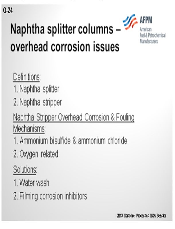
As a preface to my answer, I thought it important to define what we see as a splitter versus a stripper. To us, a naphtha splitter is a simple fractionator vessel. It takes naphtha and separates it into a light fraction that goes to gasoline blending and a bottom, heavier fraction that goes to catalytic reforming. A naphtha stripper, on the other hand, is a fractionator with a reboiler that produces the final desulfurized naphtha product from the naphtha hydrotreater unit.
With that in mind, GE does not have a lot of experience with oxygen-related corrosion issues in naphtha splitter units upstream or downstream of hydrotreaters. We do have a significant amount of experience with corrosion control in the overhead of naphtha strippers. Typically, the root causes of corrosion are associated with ammonium bisulfide and ammonium chloride deposition.
Solutions for ammonium chloride and bisulfide deposition include waterwashes and metallurgy. In some cases, filming inhibitors with good salt dispersion properties can be used to form a protective layer on the metal surfaces and disperse salts. With the waterwashes sometimes comes oxygen from oxygen-contaminated water sources. The oxygen can cause corrosion problems. In these cases, filmers with low emulsion-forming tendencies can establish a film on the metal surface to protect it from the oxygen and oxygen-related corrosion.
STREIT (KBC Advanced Technologies, Inc.)
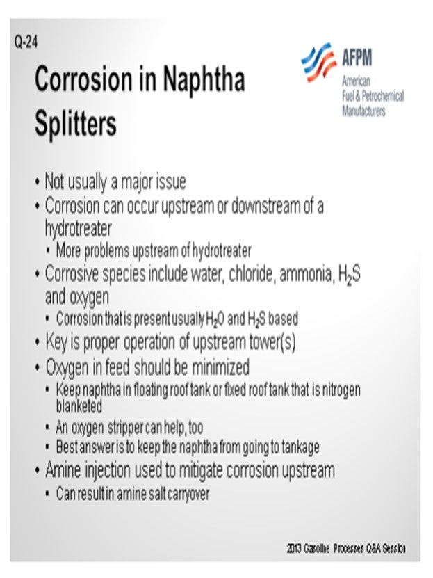
Probably one of the reasons GE does not have a lot of experience with the issues in naphtha splitters is because they typically do not have much corrosion. That being said, corrosion can occur whether the splitter is upstream or downstream of a naphtha hydrotreater. It will typically involve water, chloride, ammonia, H2S, oxygen, or some combination of those substances. Normally, it is water-based and H2S-based corrosion if it is occurring.
The main key to making sure that you do not have corrosion in these towers is to operate those splitter towers, which Ron just mentioned, correctly upstream, whether on the crude unit or after the reactors on the naphtha hydrotreater. As long as those are being operated properly, all of your corrosive, or the majority of your corrosive, materials should go overhead where they can be handled to avoid leaving you with the problem at the naphtha splitters.
One issue that can be a problem is that oxygen can get into material in tanks. Ideally, the naphtha should not be run down to a tank. Obviously, that is not always realistic; so if you do run it to a tank, you should have a floating-roof or fixed-roof tank with a nitrogen blanket. However, a fixed-roof tank with a nitrogen blanket does not always keep the oxygen out of the naphtha, especially if you pull hard on the tank. You may still get some oxygen intrusion into the tank. Putting an oxygen stripper upstream of the naphtha splitter can help to remove any oxygen that was able to get into the naphtha. You will see those on naphtha hydrotreaters every once in a while. But in general, it is not usually a big enough problem to cause worry.
In some cases, the amine injection into the naphtha splitter overhead, which Ron just discussed, can create compounds that get out of the bottom of the stripper tower and get into the splitter. When these compounds hit the hot tubes of the splitter reboiler, they cand potentially cause some corrosion. So, make sure that by treating upstream, you are not causing problems downstream a crack back into ammonia and H2S. The ammonia and H2S can move back up the splitter tower into the overhead.
RONALD GROPP (GE Water & Process Technologies)
As a preface to our response to this question, we want to state that we believe it is important to establish our interpretation of the term “naphtha splitter” versus the more common “naphtha stripper” unit.
• Naphtha Stripper: A stripper fractionation tower with a reboiler that produces the final liquid desulfurized product from the hydrotreater unit.
• Naphtha Splitter: The bottoms product from a debutanizer tower is routed to a naphtha splitter tower where it is fractionated into an overhead light naphtha product and a bottoms heavy naphtha product. The light naphtha is routed to the gasoline blending pool, and the bottoms product is fed to a catalytic reformer. There are also “naphtha splitters” in diesel hydrotreater units where the overhead of the tower is a gasoline range material that is sent to a catalytic reformer and the bottoms product is routed to the diesel blending pool.
With these unit designations in mind, GE has no experience with oxygen-based corrosion control in naphtha splitter units either upstream or downstream of hydrotreaters.
GE does have significant experience with corrosion problems and corrosion control solutions in naphtha strippers. We have experienced two primary situations:
1. Ammonium Bisulfide and Ammonium Chloride Corrosion and Fouling: A major contributor to corrosion and fouling in naphtha stripper overhead systems is ammonium bisulfide. In some cases, chloride contamination can result in ammonium chloride deposition and associated underdeposit corrosion. It is normal to control ammonium bisulfide and/or ammonium chloride corrosion and deposition with combinations of waterwashes and metallurgy. Filming corrosion inhibitors with good salt dispersion properties are also used to form a protective layer on the metal surfaces and disperse salts.
2. Oxygen-Related Corrosion: Another contributor to corrosion in naphtha stripper overhead systems is oxygen. The primary source is oxygen-laden overhead washwater. If oxygen is available to participate in corrosion mechanisms, filming corrosion inhibitors have helped mitigate the corrosion issues. The filming corrosion inhibitors are designed for effectiveness in oxygen-containing environments and provide a physical barrier to oxygen contact with the equipment metal surfaces. The inhibitors used should have low emulsification tendencies to minimize potential downstream water haze concerns in the gasoline blending pool.
CRAIG MELDRUM (Phillips 66)
Phillips 66 has seen corrosion issues on the overheads that have been attributed to chlorides and amine salts coming from poor upstream water separation. Focus on making sure feeds to the splitters are dry. That usually takes care of most of the issues, but it is often easier said than done.
ERIC STREIT (KBC Advanced Technologies, Inc.)
Corrosion can occur in naphtha splitters either upstream or downstream of a hydrotreater, although it is usually not a major issue. On splitter towers upstream of a hydrotreater, any number of potential sources of corrosion can exist including water, chloride, ammonia, and oxygen. On splitter towers downstream of a hydrotreater, the contaminants are more limited in number.
Some units have amine injection to these towers. However, this should not be necessary if the upstream tower operations are carefully monitored. The upstream stripper/debutanizer should be removing most contaminants if they are operated correctly. The problem with amine injection to the naphtha splitter is that nitrogen species can get into the light or heavy naphtha as amine salt carryover. If the heat source to the splitter is too hot, some H2S may be cracked out.
The best way to protect the naphtha splitter is to run the upstream towers to the correct temperatures to control H2S and water in the bottoms. Few folks do that and wait for naphtha splitter product issues such as drier or sulfur trap problems on the isomerization unit feed.
Oxygen can play a role upstream the hydrotreater if it has been picked up during storage or transportation. Corrosion inhibitors and antifoulants can help reduce the effect of oxygen. Some refiners have installed an oxygen stripper to remove the oxygen. Corrosion can also be caused by chloride contamination due to organic chlorides, salts from the CDU (crude distillation unit) or HCl (hydrogen chloride) in the recycle hydrogen. Corrosion inhibitors can help control the corrosion caused by HCl and NH4Cl (ammonium chloride).
PAUL FEARNSIDE (Nalco Champion Energy Services)
As crude unit throughputs have been increased over the years, the reflux drum residence time has correspondingly decreased. This is resulting in “wet” naphtha leaving the unit and feeding the naphtha splitter column. This wet naphtha contains all the acidic species normally associated with crude unit overhead corrosion. Taking steps to dry out the naphtha can go a long way towards solving/eliminating the splitter column corrosion. Increasing the internal naphtha draw standpipe height to allow more residence time for the water to settle, installing water coalescers, and utilizing emulsion breakers have all been used to help dry out the naphtha.
GARY HAWKINS (Emerson Process Management)
Emerson Process Management offers both non-intrusive and process wetted online corrosion measurement technologies to monitor corrosion due to aqueous or organic methods. The correlation of corrosion rates with other process measurements can assist with determination of causes and effectiveness of mitigation techniques.
Year
2013
Process
Question 25: What issues are encountered when introducing cracked naphthas into units that were not originally designed for the higher olefin content? What other contaminants should be considered when making this change in operation, e.g., silicon, nitrogen, and sulfur?
STREIT (KBC Advanced Technologies, Inc.)
There are many potential issues. The single most obvious one is the heat released due to the olefins. You must make sure you can handle the heat release without coking up the reactor. You also have a higher risk of furnace fouling or coking in the furnace. The higher outlet temperature from the combined feed exchangers, due to the heat release from the olefins, can result in the feed reaching a dry point prior to the furnace, which will be a big problem. You can also get more fouling in the feed exchangers, particularly if there is oxygen in the naphtha. The oxygen and olefins will form gums and lay out into your exchangers. That is a common problem when processing olefinic stocks.
You also have a higher risk of mercaptan reversion in the reactor. With the higher ∆T (temperature rise) you will get across the reactor, the reactor outlet temperature will be higher, which could result in mercaptan recombination in the outlet of the reactor. The hydrogen demand will increase as the olefins consume more hydrogen; potentially increasing coke make on the reactor. The increased hydrogen demand may get to the point where you cannot get enough hydrogen into the unit.
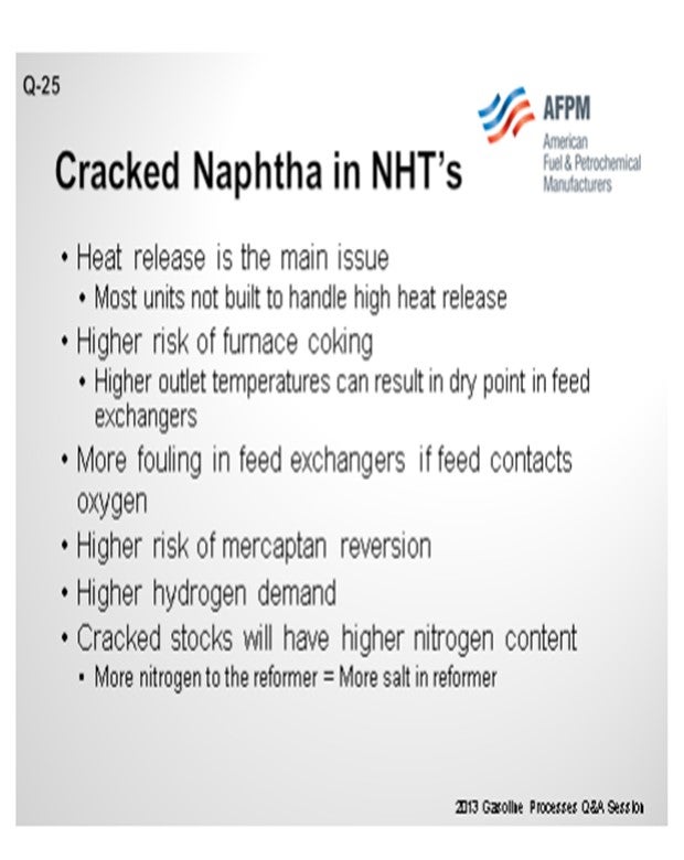
Frequently, cracked stocks will contain high levels of nitrogen. If you are going to process more olefinic material, you will probably process higher nitrogen as well. That will result in a higher nitrogen content in the outlet of the naphtha hydrotreater, which will then convert to ammonium chloride salts in the reformer.
Ammonium chloride deposition can also occur in the naphtha hydrotreater. Most naphtha hydrotreaters get their hydrogen from a reformer. If you do not have a chloride guard bed on your reformer hydrogen, you will have chlorides in it. Those chlorides can find this ammonia that is produced in the naphtha hydrotreater because of the higher nitrogen content. This can result in more ammonium chloride fouling in the naphtha hydrotreater itself.
You also have a higher risk of H2S-based corrosion; again, due to the olefins. You are also likely to get some catalyst poisons along with the olefins. Silicon is the most common one because it is used in antifoam in cokers. So, if we are talking about olefins from coker naphtha in particular, you must make sure you have an idea of how much silicon is in that naphtha. The naphtha hydrotreater needs to be designed to handle that silicon. The catalyst must be changed out before the silicon breaks through because it is very expensive if you start putting silicon into a catalytic reformer. The silicon will deposit catalyst. You want to make sure it deposits on the cheap hydrotreating catalyst (or silicon guard bed), not on the expensive reforming catalyst.
You also may have some additional sulfur species that you are not used to dealing with if you get more cracked stocks in the naphtha hydrotreater. Generally, that is not much of an issue. these days with low gasoline endpoints. However, if you are running at higher endpoints, you can actually get some harder-to-remove sulfurs that your naphtha hydrotreater may not have the ability to remove.
Finally, all of those olefins that entered the naphtha hydrotreater are going to become paraffins, so you can usually count on a low naphtha reformer feed quality from processing cracked stocks. You will probably end up with lower N+2A material going into your reformer.
ADAMS (HollyFrontier Corporation)
That was a really complete answer, so I will just say that there is going to be a bigger exotherm in the reactor, as well as polymerization and plugging in the reactor. The silicon from the coker antifoam is going to kill the catalyst. If there is slippage of the nitrogen in the effluent into the reformer, then you are going to salt up the compressor, as Eric discussed.
BULLEN (UOP LLC, A Honeywell Company)
Additionally, if you have a splitter downstream, it is possible that some of these nitrogen species could end up in the isomerization unit and kill it as well. Generally speaking, a low-pressure hydrotreater will only be able to handle about 1 ppm or so of nitrogen; so, you will get breakthrough.
There are some traps available that you can put on top of the hydrotreater bed. The traps are specific for silicon, so they lay down more efficiently compared to the catalyst. That is an option if you are going to get a steady diet, so you do not have to change out your hydrotreating catalysts as often. The previous speakers covered the rest of the topic well.
MARK ADAMS (HollyFrontier Corporation)
Generally, the exotherm is higher as hydrogen saturation and sulfur removal occur. Polymerization of conjugated diolefins occurs at normal hydrotreating conditions and causes fouling of the reactor and increased pressure drop. Silicon from coker antifoam kills the desulfurization catalyst. High nitrogen streams generate ammonia. Ammonium chloride can form and foul the reformer recycle compressor if some of the nitrogen slips through the naphtha hydrotreater into the reformer.
PATRICK BULLEN (UOP LLC, A Honeywell Company)
Cracked naphtha typically contains much higher olefin concentrations than straight-run naphtha (SRN). Olefins saturate quickly and easily in naphtha hydrotreating units (NHT). In addition to consuming hydrogen, the saturation reactions are exothermic. Depending on the concentration of olefins in the blended feed to the NHT, the temperature rise across the NHT reactor bed can exceed the design reactor delta temperature. For this reason, NHT units, which are designed to handle high olefin-containing feeds, are typically equipped to provide quench to remove the heat of reaction generated from the olefin saturation reactions.
In units that are processing higher olefin-containing cracked naphtha but which are not equipped with the ability to quench the heat generated from the olefin saturation reactions, a higher reactor outlet temperature will occur. The higher reactor outlet temperature can cause sulfur recombination resulting in off-specification high sulfur products. To avoid reaching the sulfur recombination temperature, the NHT reactor inlet temperature could potentially be decreased. However, care is required to maintain the reactor inlet temperature significantly above the dew point of the feed as to not allow for two-phase flow to the charge heater, which could negatively impact the operation and charge heater service life.
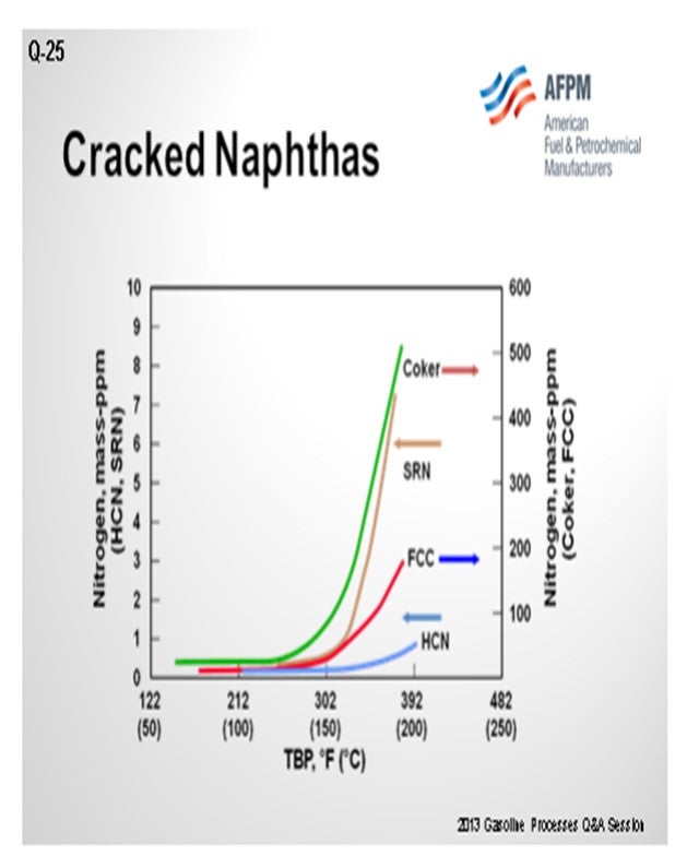
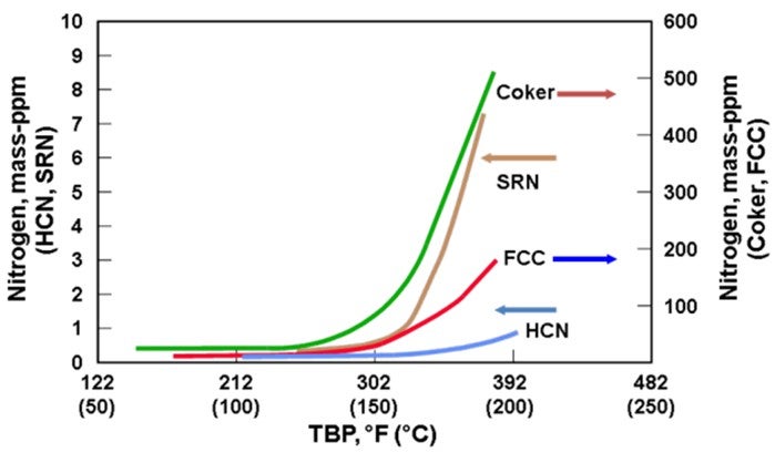
In addition to the concerns of processing olefinic feeds produced from cracked naphtha, there is also a significantly greater potential for increased feed contaminants. As seen in the chart below, full boiling range cracked naphtha has a significantly greater level of organic nitrogen in the higher boiling range relative to straight-run or hydrocracked naphthas. As a result, processing cracked naphtha can produce increased levels of organic nitrogen into the NHT. Denitrification reactions are difficult reactions to promote and are favored by high reaction pressure. If the organic nitrogen contaminate level in the feed exceeds the design criteria of the NHT reactor pressure, then the NHT product will become off-spec due to increased nitrogen. Nitrogen slipped to downstream operating units can result in both lost production and potential mechanical impact on operating equipment from the deposition of ammonium chloride in a reforming unit. For all types of isomerization units, the catalyst acid sites are deactivated by nitrogen species.
Cracked naphtha can also have high contaminate levels of organic metals: silicon (Si) and arsenic (As). These metals can be converted in the NHT at various levels of efficiency. However, the NHT catalyst will have a finite contaminate metals capacity. Once this capacity has been exceeded, breakthrough to the downstream process should be anticipated. In addition, the upstream process that produces cracked naphtha may also utilize chemical injection(s), such antifoulant and anticorrosion inhibitors. Some chemical injection compounds can contain Si that will boil in the naphtha boiling range resulting in increased contaminants being sent to the NHT.
ERIC STREIT (KBC Advanced Technologies, Inc.)
There are a number of issues with introducing cracked stocks to a naphtha hydrotreater that is not designed to handle it. These include:
1. High Reactor Exotherms and High Hydrogen Consumption: Probably the biggest issues are the increased heat release and hydrogen consumption that come from saturating olefins. Units not designed to process cracked naphthas do not have any way to control the temperature rise across the bed. As a result, the units may be limited by how high the reactor outlet temperature is allowed to go. Naphtha hydrotreaters processing virgin stocks have extremely low hydrogen consumption rates. Many units designed for virgin stock will not have enough capacity in the makeup compressors to handle a large increase in hydrogen consumption. Also, higher olefins in the feed can increase the hydrogen consumption to the point where there is no hydrogen available at the reactor outlet, causing coking and sulfur slip. As a result of the lower hydrogen partial pressure and the higher temperature at the outlet of the reactor, cracked stocks can greatly accelerate coking of the catalyst, reducing unit run length.
2. Higher Risk of Coking in the Furnace if the Higher Reactor Outlet Temperature Results in the Feed Reaching Dry Point in the Exchangers: The higher outlet temperature of the reactor can cause the unit to reach the dry point in the feed exchangers. This can increase fouling in the feed exchangers, furnace and/or reactor.
3. Higher Fouling in Exchanger Train if the Feed Comes in Contact with Oxygen: The olefins in cracked stocks will react with oxygen to form gums that can foul the feed exchangers and reactor bed. This can occur if the cracked stock is stored in tankage or if it comes in contact with other feeds that have been stored in tankage. This problem can be mitigated by ensuring that the cracked naphtha is fed directly to the unit and that any other feed that is stored in tankage is stripped to remove the oxygen. If the cracked stocks come in contact with oxygen, the fouling can become quite severe.
4. Higher Risk of Mercaptan Reversion Due to the Presence of Olefins: Adding cracked stocks to a naphtha hydrotreater will also increase the risk of mercaptan recombination. Mercaptans at the bottom of the reactor can combine with olefins to reform sulfur species that are not removed in the stripper. As a result, the sulfur level to the reformer will increase. Mercaptan recombination is more of an issue with cracked stocks due to the high reactor outlet temperature created by the heat release of the olefins in the feed and the lower hydrogen partial pressure.
5. Higher Hydrogen Demand due to the Saturation of Olefins and Potentially Diolefins: Saturation of olefins and diolefins increases hydrogen consumption in the reactor. Units designed for very low hydrogen consumption may not have the compression capacity to supply enough hydrogen to the unit when processing cracked stocks.
6. Higher Nitrogen in Product due to Higher Nitrogen in Feed and Reduced Hydrogen Partial Pressure: Many cracked stocks contain more nitrogen than virgin stocks. In addition, the lower hydrogen partial pressure that can occur due to the saturation of olefins will reduce the denitrogenation ability of the unit. The result can be a significantly higher nitrogen content in the product, which will result in increased salt formation in the reforming unit.
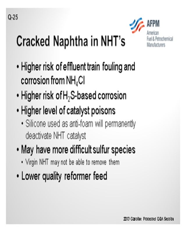
7. Higher Risk of Effluent Train Fouling and Corrosion from Ammonium Chloride: Higher nitrogen contents will result in higher ammonia concentration in the effluent. The result can be increased formation of ammonium chloride in the naphtha hydrotreaters, which will increase fouling and corrosion in the effluent train.
8. Higher Risk of Corrosion due to Higher H2S Partial Pressure: The lower hydrogen partial pressure and potentially higher sulfur levels in the feed increase the H2S partial pressure in the effluent. This can increase the risk of corrosion in the effluent train or the naphtha hydrotreater.
9. Higher Levels of Catalyst Poisons: Coker naphtha, in particular, can cause major problems in units that are not designed to handle it. Cokers use silicone as antifoam. The silicone breaks down into components that boil in the naphtha range. These components contain silicon, which is a permanent poison for hydrotreating catalyst. Not only will it kill the desulfurizer; but if the silicon makes it through the hydrotreater bed, it will permanently poison the very expensive reforming catalyst. Silicon trap catalyst should be installed in any unit that plans to process any coker naphtha. In addition to silicon, depending on the source, cracked naphthas may contain high levels of heavy metals and other catalyst poisons. These contaminants present the same type of problems as silicon. Demetalization catalyst should be included in the reactor bed configuration.
10. More Difficult to Desulfurize: Cracked naphthas may contain sulfur species that are more difficult to desulfurize. These may be able to be controlled with good cutpoint control.
11. Changes to Reformer Feed Quality (More Paraffinic or More Aromatic than Crude Naphtha): Coker and visbreaker material is highly paraffinic once it has been hydrotreated. FCC material will be more aromatic. The effect of these changes to the reformer needs to be considered if any cracked stock is added to the naphtha hydrotreater.
STEVE TREESE (Phillips 66)
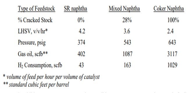
Adding cracked naphtha to a reformer pre-treat unit designed for straight-run naphtha will result in higher hydrogen consumption and increased temperature rises. Often units that previously saw no rise or a temperature loss across the hydrotreating reactor will see a much bigger exotherm. The operating conditions for SR naphtha hydrotreaters are generally much milder than you need for cracked stocks. The more severe conditions for cracked stocks are driven by the generally higher levels of sulfur and nitrogen with more difficult-to-treat types of compounds present. The presence of olefins will greatly increase hydrogen consumption, which will diminish the hydrogen partial pressure and thus decrease the high severity conditions needed for cracked naphtha treating. Some typical operating conditions for straight-run, mixed, and cracked feeds in our system are shown below. The conditions vary widely depending on the actual feedstock and the tolerable cycle length.
In addition to more severe operating conditions, you can expect an increase in fouling of the pre-heat exchangers, charge heater, and reactor(s). The fouling generally comes from polymers and gums accumulating in the exchangers or reactor and subsequently coking or further polymerizing. Exposure of the feed to oxygen or CO/CO2 (even at ppm levels) and the presence of polymer initiators in the feed lead to the gum/polymer formation. The gums/polymers deposit wherever the last feed vaporizes. It is critical that you ensure that all feed is vaporized before it enters the charge heater to avoid leaving deposits in the tubes. Such deposits have resulted in several tube failures over the years. The impact is worse with cracked stocks, which more readily make deposits and will have more heavy sulfur species that can more easily lead to sulfidic corrosion.
The cracked feeds also bring in contaminants, like silicon or arsenic, which have to be managed with catalyst choices. In a unit designed for straight-run feed only, the total catalyst volume often limits the amount of space available for the contaminant traps and hence limits possible run-length before slippage of contaminants occurs. Generally, you can run some cracked stock in a unit designed for straight-run feeds, but you have to be prepared and plan for the impacts.
CHRIS CLAESEN (Nalco Champion Energy Services)
The fouling tendency in the pre-heat and reactor can increase significantly due to polymerization of the olefins and diolefins. Chemical programs with antipolymerants, dispersants, and reactor bed cleaners can help control polymerization and delta P. Nitrogen and sulfur content will mainly depend on the type of feeds that are processed by the cracking units. Silicon can be a contaminant when coker gasoline is processed due to contamination with antifoam breakdown products. In such a case, the coker antifoam program should be carefully controlled and Si contamination minimized.
GREG SAVAGE (Nalco Champion Energy Services)
The instability or reactivity of an HDS feedstock will relate directly to its fouling potential. For refinery streams, the processing history of a stream plays a significant part in defining its instability. Streams produced in thermal cracking processes, such as cokers and visbreakers, will contain high levels of olefins, diolefins, and other fouling precursors that make these stream the most unstable in the refinery. Streams produced in the catalytic cracking units will contain moderate levels of olefinic species. Straight-run streams, those coming directly from the crude unit, will not naturally contain olefins and are Therefore, usually very stable. (If unstable streams are reprocessed in the crude charge, the straight-run streams may contain some reactive material.) The presence of intermediate storage must also be considered, as dissolved oxygen contamination will greatly increase the fouling potential of a normally stable feedstock.
The propagation of the olefin polymerization involves the reaction of an olefin with a radical, which results in the formation of another radical. This reaction path continues and results in molecular enlargement of the polymeric foulant. Eventually, the molecule will become too large to remain buoyant in the process stream and will precipitate out onto the equipment surfaces. These reactions are accelerated with the higher temperatures found in the pre-heat exchangers of an HDS.
Carbonyls are often initially formed by the presence of free oxygen contamination in a process stream. Further reaction of the carbonyls can lead to a variety of polymeric species that can contribute to fouling. As more oxygen is incorporated into a polymer, it will eventually become insoluble in the hydrocarbon stream and precipitate onto equipment surfaces.
Metals (particularly iron) are almost always present in significant quantities in most refinery streams. The role of metals in the physical and chemical fouling mechanisms must be considered when considering fouling deposit and stream characterizations. Metals catalyze decomposition of peroxides to reactive radicals, which promotes polymerization (gum forming) reactions.
Higher sulfur, nitrogen, and olefin content in cracked naphtha and mid-distillate streams have resulted in the need for increased HDS severity, which accelerates polymerization reactions.
For limiting polymeric gums formation, it must be known whether the polymerization is the result of oxidation reactions, metals or unstable feedstocks, or some combination of these mechanisms.
For oxidation reactions, the most effective corrective measure is to reduce or eliminate the free oxygen that is contaminating the feedstock. The application of antioxidants is also applied to prevent oxidation reactions.
Metals contamination is addressed first by determining and then eliminating the source of the metal foulants. Metal deactivators and dispersants can be applied to limit the adverse effects of metal in HDS feedstocks.
For highly reactive streams, antipolymerants can be applied to limit the gums-forming potential of these unstable feedstocks, and dispersants can be used to prevent the agglomeration of foulant particles, keeping them in a finely divided state.
Year
2013
Process
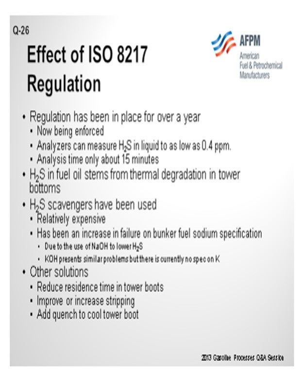
Question 26: How will the ISO 8217 Marine Fuel Oil Hydrogen Sulfide (H2S) specification (less than 2 ppm H2S in the liquid phase) affect refiners? Do any refiners plan to implement the standard, and what procedural or equipment changes are likely needed in order to meet the specification?
GROPP (GE Water & Process Technologies)
Simply put, refiners will be required to meet the ISO 8217 2 ppm H2S specification if they are going to sell fuel oil to customers who have requirements to meet this specification. ISO 8217 is a fuel specification, not a regulation. A regulation is enforced by some regulatory organization. Ironically, in 2008 the International Maritime Organization (IMO), which is an international regulatory body, approached the ISO (International Organization for Standardization). IMO asked the ISO to review the ISO 8217 Marine Fuel Oil specification and make recommendations to ISO regarding specific fuel parameters, including H2S levels. ISO commissioned a task force; and after a lot of work, the task force produced a test method and 2 ppm H2S specification for marine fuel oils. Analyzers are now available to measure H2S in the liquid phase of fuel oil. After reviewing the method and specification, IMO decided not to adopt the ISO recommended 2 ppm specification stating their decision that H2S levels are a contractual matter between buyer and seller. Therefore, at least at this point, they did not include H2S in their marine fuel regulation.
From GE’s point of view, we are seeing a number of our refining and marine fuel oil trading customers adopt the specification. In some cases, refiners must reduce H2S in their liquid streams, particularly the heavy resid fuels, to meet the specification. The options available include capital equipment upgrades in the form of additional hydrotreating capacity and/or stripper modifications, blending with low H2S components, and the use of H2S scavengers to tieup the H2S. Our experience to date indicates that most refiners are tweaking their existing processes, paying particular attention to blend compositions, and then utilizing H2S scavengers whenever it makes sense to meet the specification.
STREIT (KBC Advanced Technologies, Inc.)
When I first saw this question, I thought, this is the Gasoline panel, right? because I am not used to dealing with this black oil stuff. So, I had to study up on this myself. I learned a lot of the information that Ron discussed. At KBC, the places we have seen this being an issue are where there is H2S in the fuel oil. It is generally caused by thermal degradation in the tower bottoms. So, you hit high temperatures in vacuum tower bottoms or in main fractionator bottoms, H2S is formed at these high temperatures and not stripped from the tower bottoms. The tower bottoms are then blended to bunker fuel.
In my reading, there was discussion about the scavenger use, which can be relatively expensive depending on how much fuel are you making. The industry has recently had a lot of excursions on sodium in bunker fuel, so it appears that some places are using sodium hydroxide to neutralize the H2S in the stream. Potassium hydroxide is also being used. Although there is no spec on potassium, it does cause much of the same problems in the scrubbers as the sodium does. So, it would not surprise me if there was some pushback on the potassium levels in the future.
So how do you prevent the bunker fuel from containing H2S in the first place? One operational adjustment you can do is reduce the residence time in the boots of those hot towers. Reducing the time that the bottoms material sees the high temperatures reduces the likelihood that it will degrade and form the H2S. In some cases, the problem may be in the ability to strip the H2S out of the bottom's material. Improving your stripping trays or increasing the number of stripping trays in the bottom of a hot tower can increase the ability to strip H2S. Another possibility is to add a quench to the boot to keep the temperature of the boot down lower and avoid creating H2S.
GROPP (GE Water & Process Technologies)
I want to build on what Eric said a little. You do have to be careful which H2S scavengers you employ, particularly if you are going to use a simple inorganic base compound like sodium hydroxide or potassium hydroxide. The reason is the inorganic base forms an ionic bond with the H2S, and the reaction is very much reversible in the presence of strong acids and/or high temperatures. So the treated fuel can be a hazard aboard ships or wherever the fuel is used. If the treated fuel comes into contact with a strong acid or high temperature, the base may release the H2S. We recommend H2S scavengers that produce non-reversible reactions.
JESSY TRUCKO (UOP LLC, A Honeywell Company)
As a UOP treating specialist, I do not usually deal with this. I imagine that using sodium hydroxide in this service would really look like a mess to me because of all the kinds of organic acids in there that will end up causing emulsions. My comment is that it is really no surprise that you are getting sodium hydroxide carryover due to those emulsions. I mean, that has to be a mess. If you were going to try it, you would have to use a weak sodium hydroxide. You would probably also have a lot of sodium hydroxide to try to minimize those emulsions, as well as probably having some kind of electrostatic precipitator downstream of it to coalesce out the sodium hydroxide.
STREIT (KBC Advanced Technologies, Inc.)
I think that is a good part of the reason why the sodium levels are so much higher. All of these sodium excursions are happening now that did not occur in the past just because people are trying to get on-spec on H2S and maybe do not know how..
RONALD GROPP (GE Water & Process Technologies)
Simply put, refiners will be required to meet ISO 8217 Marine Fuel Oil Hydrogen Sulfide (H2S) specifications if they sell fuel oil to customers who have requirements to meet the 2 ppm H2S specification. ISO 8217 is a specification, not a regulation. Regulatory and enforcement agencies must adopt and enforce the specification for it to have any “teeth”. For example, in 2008, the IMO (International Maritime Organization) asked the ISO (International Organization for Standardization) to review the ISO 8217 Marine Fuel Oil specification and make recommendations to IMO regarding specific fuel parameters, including H2S levels. In 2011, IMO elected not to adopt the ISO recommended 2 ppm maximum H2S level established in the latest Marine Fuel Oil specification (ISO 8217:10) for the latest version of MARPOL (International Convention for the Prevention of Pollution from Ships) 73/78, Annex VI Regulation 18 (Fuel Availability and Quality). In fact, MARPOL elected not to include an H2S limit in the regulation. In summary, regulatory agencies and their constituents make decisions to adopt specifications and enforce them or not.
From GE’s point of view, several of our refining and fuel trader customers are producing fuel to meet the 2 ppm H2S specification. We do not have detailed geographic survey information regarding ISO 8217 adoption.
To meet the 2-ppm specification, many refiners must reduce the H2S content of their fuels, especially heavy fuels. Options available to accomplish this include:
1. Capital equipment upgrades, such as increased hydrotreating and/or stripper modifications,
2. Blending with low H2S content streams, or
3. The use of H2S scavenging additives. Our experience indicates that most refiners are tweaking existing process equipment, paying close attention to blend compositions, and employing H2S scavenger additive programs such as those offered by GE.
ERIC STREIT (KBC Advanced Technologies, Inc.)
The 2 ppm H2S limit for marine fuel oils associated with ISO 8217 was put in place in July of 2012. However, it has been difficult to enforce due, at least in part, to the inability to accurately measure these low levels of H2S in the liquid fuel oil. Analyzers have been developed that can purportedly measure H2S down to 0.4 ppm levels with only a 15-minute processing time. With this new analyzer ability, ISO 8217 is more likely to be enforced.
In refineries where we have seen a problem with H2S in the fuel oil, the issue has stemmed from H2S being created by thermal degradation in hot tower bottoms, mainly vacuum towers. H2S scavengers have been added to meet the specification; but this can be expensive, so other longer-term solutions have been examined as well.
In wet vacuum towers and visbreaker columns, stripping steam can be increased to remove H2S from the tower bottoms. Crude tower stripping steam has been increased as well, but with a lesser effect. Installing a steam sparger in the bottom of the vacuum tower can help improve stripping and thus lower H2S in the bottom's product.
Reducing the pressure in the vacuum column can also help strip more of the H2S. These solutions focus on stripping the H2S rather than preventing it from forming in the first place. Reducing the residence time in the vacuum tower bottom sump can help reduce the amount of H2S that forms due to thermal degradation. Adding a quench to the vacuum tower boot can be used to reduce the vacuum tower bottoms temperature, which also reduces thermal degradation.
Another potential source of H2S in fuel oil is a leaking exchanger. If H2S is detected in the fuel oil, refiners should look for other symptoms that may indicate an exchanger leak and repair any leaks that are detected.
PAUL YON-HIN (Nalco Champion Energy Services)
In principle, the ISO 8217 Marine Fuel Oil Hydrogen Sulfide specification of less than 2 ppm in the liquid phase is to be practiced by refiners, but that is not necessary the case since they may just manufacture components of the marine fuel. It then then becomes the blender’s responsibility to manufacture a finished marine product that meets the ISO 8217 specification. With the introduction of the ISO 8217 specification for H2S level for health and safety reasons, refiners are now monitoring their H2S level in their products. Typically, they want to have products that have less than 10 ppm of H2S level in the vapor phase in their storage tank at the refinery. Such fuel will easily pass the 2 ppm H2S level in the liquid phase. To implement the ISO 8217 H2S specification, a new and rapid method has been developed and introduced to measure H2S level in the fuel oil as described in IP 570 Method. At the refinery or blender locations, if the H2S level is higher than the limit of 2 ppm, then a H2S scavenger use is the best way to bring the fuel on-spec for H2S level in the most economical way. No equipment changes were needed to implement this new H2S specification at the refinery. Some refiners have acquired the instrument to run the IP 570 test method.
Year
2013
Process
Emerging Leaders/First Timers Reception
Session Start End
-
Registration
Session Start End
-
Keynote
AFPM is pleased to announce that the Deputy Director for the Cybersecurity and Infrastructure Security Agency (CISA), Nitin Natarajan, will be the keynote speaker at the 2024 Security Conference. Director Natarajan is no stranger to the petrochemical and refining industry, having spoken at the 2023 AFPM International Petrochemical Conference and the AFPM sponsored Sam Houston University Institute of Homeland Security Thought Leaders Conference. In this keynote session Director Natarajan will discuss the role government and public-private partnerships will play defending against unconventional and new cyber attacks upon critical infrastructure.
Speakers
Session Start End
-
USCG Session: Cyber, Drones, and the Future TWIC Reader
Hear the latest on the TWIC Reader rule, future USCG cyber actions, and other MTSA issues.
Speakers
Session Start End
-
Artificial Intelligence (AI) Security Issues: Pros & Cons
This session will review the potential security risks and security benefits of AI in the petchem and ONG industry.
Speakers
Session Start End
-
Break
Session Start End
-