
Question 75: In your experience, how does the shape of an FCC catalyst particle impact the fluidization properties of the catalyst? What other properties are important to monitor?
ALEXIS SHACKLEFORD and SHAUN PAN (BASF Corporation)
The key catalyst properties affecting fluidization are particle size distribution, particle density, and particle shape. Fluidization studies have shown that a change in catalyst shape from spherical to oblong gives a 19% reduction in deaeration rate, due to more drag force with an oblong particle: meaning, itis harder to defluidize this material. However, catalyst with irregular particles and sharp edges, such as attrition generated particles, are harder to unlock and fluidize. Fluidization equations, as appear in the literature, often drop out the shape factor since it is difficult to determine, including the Abrahmsen and Geldart Umb / Umfequation (1980) and Coltters and Rivas (2004).
The variable that affects catalyst fluidization the most is the quantity of less than 45 microns particles (or fines) in catalyst. A catalyst with a range of particle size flows more smoothly than one of uniform size. The smaller particles fit between the larger ones, acting as a lubricant to make flow easier. Improvements in fluidization can also be made by a reduction in e-cat density and a change in particle shape. A reduction in the 80+ microns fraction has an influence, but it is not a major factor.
The following important properties should also be closely monitored:
1. ABD
2. 0-to-45-micron fines content,
3. APS (average particle size), and
4. Attrition, as irregularly shaped particles with sharp edges do not fluidize well.
Year
2016
Process
Question 75: The butane stream from a catalytic polymerization (cat poly) unit, which contains 69% isobutene, 14% butylenes, and 17% normal butane, would appear to be an excellent alkylation unit feedstock, especially if isobutene is i
METKA (Sunoco, Inc.) We operate a cat poly and sulfuric alkylation unit within the same refinery. The configuration offers flexibility and synergies that allow various operating and business demands to be met. In our configuration, the cat poly debutanizer overhead feeds the alkylation unit to recover the isobutane and any remaining butylenes.
Similar to our other SPA experience, acid carryover from the effluent filtration system typically drops to the bottom of the downstream fractionators resulting in fouling and corrosion of the reboilers. Historically, we have not experienced any significant impact on the alkylation unit or sulfuric acid quality due to carryover from the cat poly unit. If carryover were to occur, we do expect that the phosphoric acid would be more of a corrosion and fouling concern than an acid consumption issue.
Below is a plot that basically shows the way in which the plants are configured. The BB is treated and split to the cat poly and alky units in parallel. Once we recover the C4s off the backend of the cat poly plant, the stream is fed back into the alkylation unit.
Gasoline ProcessesGasolineProcessesFCCDebutDepropBtmsCat GasolineC4,C4=PolyTreaterAlkyContactorsDepropDebutDepropBtmsLPGPolymer GasolinenC4,iC4ContactorEffluentDIBDebutnC4/AlkylatenC4AlkylateMake-up C4iC4PolyAlkyFCCGasolineMixed ButaneiC4nC4Rxr EffluentTreated C4, C4=EffluentTreatingPolyRxrs (FUNKY GRAPHIC)
ZMICH (UOP LLC) I have three points that I would like to make.
1) UOP does not have experience with traces of phosphorus in the alkylation unit feed.
2) UOP strongly recommends avoiding the possibility of phosphorus in the feed. The reason for this is that a combination of mineral acids will lead to a more aggressive corrosion than either of the two acids by themselves.
3) From a commercial perspective, UOP is aware of at least one refinery that feeds cat poly stream with feed from an FCC to an alkylation unit, and the process flow is shown in words as such: “Process flow is a stream goes through a water wash to remove phosphoric acid, the sand tower acting like a coalescer, and a UOP MeroxTM unit to remove sulfur before going to the alkylation unit.
Year
2008
Process
Question 35: How far can the hydrogen to hydrocarbon ratios be decrease in gasoline hydrotreating units before experiencing high reactor pressure drops? Please provide some details of your experience with reference to the run length limitations and operating performance.
Ujjal Roy (Indian Oil Corporation)
We have number of naphtha hydrotreatment units in our refineries, some operating with straight-run naphtha as feed and others in mix mode with significant cracked feedstock varying from 10% to 40%, to produce feedstock for catalytic reformers. I suppose, the question here is for hydrotreating units processing cracked components.
Straight-run naphtha hydrotreatment units, in our case, are designed for low pressure (i.e. 20-25 kg/cm2.g) and with 40-75 Nm3/M3 of gas to oil ratio depending on feedstock characteristics and desired product quality. In case of hydrotreaters designed to process FCC gasoline, designed gas to oil ratio is about 400 – 500 Nm3/M3 of feed operating at about 50 kg/cm2. The designers recommend the partial pressure of hydrogen through gas oil ratio and system pressure based on the given feed characteristics and target product w.r.t. olefin, sulphur and nitrogen content. Difficult feedstocks with higher nitrogen content require higher hydrogen partial pressure. Reduced gas to oil ratio can only be compensated partially through higher RIT for equivalent nitrogen removal. But running at higher RIT compensating for lower gas to oil ratio with cracked component in feed will accelerate the coking rate on catalyst leading to high pressure drop. Coke formed on the top of catalyst bed can lead to excessive pressure drop and channeling within reactor which will reflect in radial temperature spread. Delta T across the first bed of the reactor will increase due to less availability of hydrogen as heat sink. Also, lower gas to oil ratio aggravates coke formation in the preheat exchangers resulting in high pressure drop. All these would finally lead to slippage of sulphur and nitrogen in product apart from reduced cycle length. This phenomena has been experienced in one of our hydrotreaters with cracked component in feed due to problem in RGC resulting in low flow over days. We normally do not practice lower gas to oil ratio below recommended value as the penalty is large over the time period as compared to pushing extra capacity or reduced energy consumption.
However, in one of our units, we have optimized gas to oil ratio to nearly 90% of recommended value with the advice of licensor, by shifting some reaction from Bed-1 to Bed-2 through reduced reactor inlet temperature in Bed-1 and reduced quench rate in Bed-2. This in turn has led to ascending temperature profile i.e. drop in Bed-1 peak temperature as compared to that of Bed-2 peak temperature. By doing so, we could maintain uniform radial temperature and no appreciable increase in reactor Delta P since about two years of operation inferring no appreciable reduction in run length due to these adjustments.
In case of coking or fouling, pressure drop across reactor will increase steadily over operation and spikes are not expected. Despite maintaining design gas to oil ratio in many of the hydrotreaters, we have experienced high pressure drop leading to frequent skimming of catalyst bed. The reasons for these incidents have been identified to be caustic carry over from upstream caustic wash units, dissolved oxygen in tank wagon while being transported from one refinery to another and carryover of foulant from feed tanks.
The decrease in run length on account of lower gas to oil ratio operation on continuous basis is a factor of type of feedstock i.e., olefin, sulphur and nitrogen contents and target product specifications. In case of margin available in the feedstock quality, gas to oil ratio can be optimized based on adjustment in reactor severity and conversions.
Praveen Gunaseelan (Vantage Point Consulting)
It is assumed that the question pertains to FCC gasoline hydrotreating. Due to the variability in unit designs, process configurations, feed compositions, contaminant levels, product quality targets, etc., a specific answer to the question cannot be provided. For site-specific guidance, refiners are advised to consult with the gasoline hydrotreating process licensor or a qualified engineering contractor.
Maintaining adequate partial pressure of hydrogen is a critical element of hydrotreater operation, as it minimizes coke formation on the catalyst. An adequate feed gas to oil ratio is also essential as the gas plays a critical role in heat removal from the reactor. For these reasons, hydrotreating process licensors often require a minimum gas to oil ratio during operation to prevent premature catalyst deactivation and reactor overheating. While a common rule of thumb is that the minimum gas to oil ratio should be at least 4 times the hydrogen consumption per barrel of feed, it is critical to recognize that this ratio is inherently unit-specific, and the licensor or designer’s operating recommendations should be strictly followed.
Other potential complications of operating at low hydrogen to hydrocarbon ratios include reactor fouling due to incomplete saturation of diolefins, accelerated catalyst deactivation due to higher temperature operation, and unsatisfactory product quality.
The chapter on Hydrotreating by A. Gruia in the Handbook of Petroleum Processing (D.S.J. Jones, P.R. Pujadó, eds., Springer, 2008) has useful information pertaining to this question.
Olivier Le-Coz (Axens)
As a general guideline, in viewpoint of catalytic performances and cycle length it always recommended to operate naphtha HDS reactors at maximum recycle gas rate. Because those reactors operate in gas phase Hydrogen partial pressure is significantly affected when the recycle gas rate varies. Maximized recycle has rate and thus Hydrogen partial pressure, allows minimizing catalyst temperature and maximizing cycle length. In the case selectivity towards HDS versus olefins saturation is targeted, maximizing recycle gas rate to maximize hydrogen partial pressure and minimize catalyst temperature is crucial.
Brad Palmer (ConocoPhillips)
COP sets the lower limit on gas/oil ratio at 300 scf/b (with a minimum of 70% hydrogen in the treat gas). Remember that the hydrogen is diluted by vaporized hydrocarbon, especially in a naphtha unit. Hydrogen partial pressures are actually very low. We also set a minimum of 3:1 treat gas hydrogen to chemical hydrogen consumption, i.e., the treat gas hydrogen rate per barrel must be at least 3 times the per-barrel hydrogen consumption. Both of these criteria are supposed to be met. In practice, some units do not meet the minimum rates.
Once the minimum is met, there are many other factors that are more critical than the hydrogen/oil ratio. These factors include the operating pressure, LHSV, feed composition, feed contaminants and percent cracked stock.
With respect to hydrogen gas/oil ratios, we can offer direct comparisons where two units feed essentially the same feedstock and operate at primarily the same conditions, except for the gas/oil ratio. The best comparison basis is barrels of oil processed per lb catalyst because in this case the units do not have exactly the same catalyst volumes.
•Case 1: Straight-run naphtha feed at about 360 psig. One unit has more catalyst in it, but the cycle lengths are the same at 18 months. One unit has 140 scf/bbl hydrogen and the other has 270 scf/bbl. The oil amounts processed in 18 months in these units are 195 and 241 Bbls/Lb catalyst, respectively. The unit with the higher gas rate processes about 24% more oil per pound with a gas/oil ratio about 93% higher.
•Case 2: Straight-run naphtha feed at about 450 psig. Again, the amounts of catalyst in the units differ, with the cycle lengths the same at 48 months. Gas/oil ratios are 570 scf/bbl and 710 scf/bbl. The barrels per pound catalyst processed are 571 and 740, respectively. The unit with the 25% higher gas rate can process about 25-30% more oil.
Year
2011
Process
Question 26: What is your Best Practice for packing (material and shape) in isomerization unit off gas caustic scrubbers?
DUNHAM (UOP)
UOP recommends carbon Raschig rings. The key here is to specify to the vendor that this be used for caustic service so that the rings will be formed with the proper binder. If you get the wrong binder, the rings will dissolve. We have a similar service in HF alky units where we use carbon Raschig rings; and there, you have to make sure that the binder is resistant to acid. So, you cannot switch the two. I have seen the carbon Raschig rings ooze out of the tower when a customer bought the wrong binder.
Another material you can use is chemical-grade polypropylene. This is plastic, so it does have temperature limits. If you use this kind of material, you have to be careful not to steamout the tower because this packing is good for the operating temperature of the unit. But if you steam it out, it will melt, and all come out in one piece.
LAMBIE (KBC Advanced Technologies, Inc.)
My experience has only been with the carbon Raschig rings. I have not seen any issues with them in any other sites. My only other comment to add to Daryl’s is that the use of ceramic rings is not recommended because they are not compatible with caustic.
DOMINIC VARRAVETO (Burns & McDonnell)
My question is related to the scrubber. Have there been any comments from the operators of these units with upsets that cause caustic to go backwards into the stabilizer and create plugging in the stabilizer overhead system?
LAMBIE (KBC Advanced Technologies, Inc.)
I have not seen or heard of this happening. Normally there is a check valve in the line to prevent any backflow from the caustic scrubber to the stabilizer.
RICK GRUBB (Chevron Products Company)
We have experienced caustic back-flowing in the overhead receiver drum, so we have installed quick-acting ball valves that activate pressure differential. When the pressure differential gets low enough, it will close the valve.
SCOTT LAMBIE (KBC Advanced Technologies, Inc.)
One-inch OD carbon Raschig rings have been the standard packing material for isomerization unit off gas caustic scrubbers. Use of this packing material has proven to be very effective in minimizing caustic breakthrough and water carryover. Operating the unit per the design circulation flow rates of caustic and water insures proper wetting of the packing material for maximum effectiveness.
The use of ceramic packing material should be avoided as caustic will attack and degrade the material.
Year
2015
Process
Question 74: In your experience, what are the effects of different Ni passivation technologies on the performance of CO promoters and stack emissions?
ZACH BEZON [United Refining Company (URC)]
Nickel passivation can be accomplished a few ways: antimony, bismuth, or sulfur. Adding antimony or bismuth in a solution, such as LCO, will immediately begin to passivate the negative effects of nickel poisoning. Antimony is considered a fugitive emission and may be hazardous; bismuth may be the safer option. Antimony decreases the effect of CO promoter; additionally, it can lead to elevated NOx emissions. Refinery fuel gas containing H2S can be used as lift gas and act as a temporary nickel passivator in the reactor, helping to reduce hydrogenation reactions. However, this effect is only temporary and will lead to elevated levels of nickel if nothing further is done.
CHRIS CLAESEN (Nalco Champion)
Pt promoters are sometimes used to oxidize CO to CO2in the regenerator. Antimony can passivate platinum promoters, which can result in afterburn and the need to use more platinum promoter. The Pt promoter oxides nitrogen compounds, as well as CO; so, the more Pt promoter that is used, the higher the NOx. Therefore, Sb (antimony) can theoretically result in higher NOx. Units using a Pt-based combustion promoter can consider a switch to one of the non-Pt combustion promoters if they want to eliminate the effect of increased NOx generation.
DENNIS HAYES (Nalco Champion)
Antimony-based additives are known to be effective at nickel passivation, but they have also been reported to reduce the effectiveness of CO promoter additives, resulting in increased usage of the additives.
ALEXIS SHACKLEFORD and BILGE YILMAZ (BASF Corporation)
Using antimony for Ni passivation will make CO promoters less effective. For example, one unit running 1000 ppm e-cat (equilibrium catalyst) Ni started using antimony, targeting a 0.35 Sb/Ni ratio. They had to increase their CO promoter additions from 1.1 ppm platinum (Pt) in inventory to 1.6 ppm Pt, or 50%. Running economics around unit profitability, the refinery found that using antimony improved profitability by 0.15 $/bbl (cost per barrel) due to lower hydrogenand coke. Even though this unit had relatively low Ni at 1000 ppm and had to use more CO promoter, the benefit of antimony at 0.15 $/bbl was significant, and they continued to use antimony.
For units that have operational challenges using antimony, Ni passivation based on catalyst technology is an attractive route. For example, the use of boron-based technology (BBT),developed by BASFand used in our catalyst BOROCAT™, has been demonstrated successfully in commercial operations to passivate Ni without impacting stack emission or CO promoter efficacy.
Year
2016
Process
Question 66: Some refiners are considering substituting potassium hydroxide for sodium hydroxide as a desalted crude treatment to lower overhead chlorides. What is the impact of this change on coker operation and other downstream units? What are the advantages and disadvantages?
DION (GE Water & Process Technologies)
They are both alkali metals. Potassium hydroxide should, in theory, act like sodium hydroxide. The effect should be similar with regard to reducing the overhead chlorides in the desalted crude or, similarly, in metal-catalyzed fouling. Potassium hydroxide does have the potential to be used as a tracer; for instance, it can be injected in the desalted crude. The bottoms and heavy gas oil fractions can be analyzed for potassium to determine the disposition of adding an alkali metal to the desalted crude. Potassium hydroxide is typically more expensive than sodium.
DION (GE Water & Process Technologies)
Potassium is an alkali metal just like sodium. Its ability to reduce the overhead chlorides is expected to be comparable to that of sodium. Just like sodium, it will contribute to metal catalyzed polymerization in downstream units. There is no known advantage to using potassium other than the fact that it can be used similar to a tracer to quantify the impact of metal hydroxide addition to downstream units. Potassium hydroxide is typically more expensive than sodium hydroxide. While there are no common potassium specifications for finished fuels, its potential negative impact in the fuel should be similar to that of sodium.
BASHAM (Marathon Petroleum Corporation) Potassium hydroxide is more expensive than sodium hydroxide. It is expected that the potassium ion will catalyze the cracking reaction and promote coking in the same manner as the sodium ion. Therefore, we do not see an advantage in using potassium hydroxide.
LEE (BP Products North America)
Sodium chloride is a very stable chloride and has a very high temperature for hydrolysis. We are not sure that there is any benefit from using potassium chloride as a base to control the overhead chlorides. We think that sodium will catalyze coke formation in the vacuum and coker heaters at concentrations of over 15 ppm. We think that potassium will do the same thing. Sodium is a poison for the downstream hydroprocessing units and so is potassium. We are not sure there is any benefit here.
ANDREW SLOLEY (CH2M HILL)
Potassium hydroxide has a lower potential to induce stress corrosion cracking than sodium hydroxide. Little direct experience is available to quantify this. However, test work targeted at syngas systems showed significantly increased temperatures were required for stress corrosion cracking to occur. This may be a benefit for the crude unit between the desalter and the crude tower.
Year
2012
Process
Question 45: What are the procedures/rules governing the transportation and disposal of catalyst contaminated with arsenic, mercury, barium, or other heavy metals? Are there maximum limits for any of these?
SHARPE (Flint Hills Resources, LP)
The spent catalyst needs to be shipped offsite and sent for metals reclamation or disposal. If it is going for disposal, it will have to be characterized to determine if 1) it is a hazardous waste, which it is most of the time, and 2) it meets the applicable Land Disposal Restrictions (LDRs). It would have to be treated, as part of disposal, to meet the LDRs.
Regarding transportation, if the catalyst needs to be shipped offsite for reclamation, it will have to be determined if it is hazardous material or contains hazardous substance. So by default, spent catalysts generally fit into that category. Take a look at the Hazardous Materials’ Table listed on the slide.
Overall, there are no maximum limits for disposal or transportation, but the catalyst does have to be transported and disposed of properly. It ends up being classified as a hazardous waste and subject to all the laws regarding that classification.
CHRIS STEVES (Norton Engineering)
The transportation and disposal of spent catalysts are governed by DOT (Department of Transportation) and RCRA (Resource Conservation and Recovery Act) regulations. A spent catalyst with leachable levels of arsenic, mercury, or barium (or five other regulated heavy metals) above their TCLP limit, will be regulated by the U.S. EPA (Environmental Protection Agency) as RCRA hazardous waste. If the material is spent hydrotreating catalyst from the petroleum refining industry, it will automatically be regulated as RCRA hazardous waste regardless of the metals content. Regulated RCRA hazardous waste must be properly disposed of at an approved treatment, storage, and disposal facility (TSDF). The actual levels of contamination will affect the options and cost for disposal. All RCRA hazardous wastes are regulated as DOT hazardous materials when shipped offsite, and all the basic rules for hazardous materials shipment must be followed.
Year
2013
Process
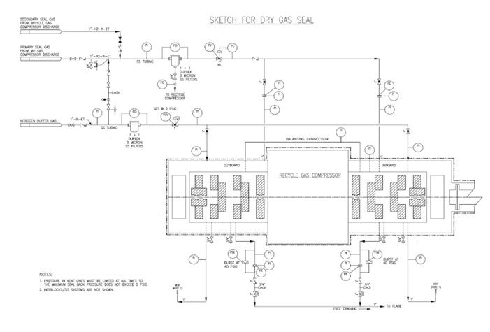
Question 4: How reliable are the dry gas seals on hydroprocessing recycle gas compressors? What are the system components put in place to enhance the reliability?
Shankar Vaidyanathan (Flour)
Dry gas seals have been used for compressors for many years. The feedback was mixed in its infancy, and there were teething problems. External factors such as the contamination of the sealing gas, insufficient sealing gas pressure and process gas leak onto the seal ring surfaces have been the main reasons for seal degradation. Wetness, particulates, and heavier hydrocarbons cause seal reliability issues. The quality of seal gas and buffer gas, dryness level, pretreatment, liquid separation and filtering are the keys to reliable operation. Experience has shown that seals can last a long time in a clean environment and many existing plants have switched over to gas seals. Tandem self-acting dry gas seal with internal labyrinths has been selected in many recent projects.
Please see the attached sketch for external components of the dry gas seal system.
1. Depending on pressure balance, the sealing gas may be pure makeup hydrogen (if the makeup compressor is located within the same plot) or recycle compressor discharge gas. Chlorides in makeup hydrogen and amine aerosols in recycle hydrogen are potential contaminants.
2. Nitrogen is used as the buffer gas.
3. Filters for seal gas and buffer gas should be duplex, one operating and one standby, 3-micron stainless steel coalescing filters equipped with high differential pressure alarm. Avoid three-way valves for filter switching.
4. Consider additional pre-filter for sealing gas if experience has shown that coalescing filters are inadequate. Consider additional demister filter for buffer gas if necessary.
5. Minimum 1” size stainless steel piping is preferred. Additional notes for piping layout include minimizing runs, avoiding pockets, heat tracing and winterizing as necessary.
6. The seal gas injection is on automatic pressure control.
7. Primary vent is routed to flare; secondary vent is routed to safe atmospheric location.
8. Primary seal vent flow is monitored with high flow and high-pressure alarms.
9. Pressure in the secondary vent line must be limited such that the maximum seal backpressure should not exceed 5 psig.
10. Consider differential pressure alarm between the buffer gas and secondary vent.
Minh Dimas (CITGO)
Dry gas seals are more reliable than oil seals provided the seal gas conditioning system is properly designed, and the seal gas is very clean and dry. That said, the filtration and liquid removal system must be very reliable and have spare equipment to maintain its reliability. Tandem dry gas seals require a source of very clean, dry seal gas at startup.
Year
2011
Process
Question 75: What are the potential problems or negative impacts of utilizing FCC slurry/decant oil as coke drum OH (overhead) line quench oil?
SRIVATSAN (Foster Wheeler USA Corporation)
Again, FCC slurry/decant oil has a similar distillation range to HCGO but a higher endpoint. Although it could possibly be used as just overhead quench, we caution that if the slurry/decant oil is not be filtered properly, it will contain catalyst fines that could accelerate the coke deposition by settling in equipment or piping. We normally recommend using the blowdown tower bottoms as the primary source for quenching the overhead vapor line. The secondary means of quenching is provided using HCGO. LCGO and other gas oils, including slops, can also be used as desired.
PRIBNOW (CITGO Petroleum Corporation)
We do not have any experience using slurry oil as coke drum overhead quench. We utilize slop oil, as Srini mentioned, as a way to vaporize and reprocess that material. We charged slurry oil to our coker when excess capacity was available. However, we found that it degraded the heavy coker gas oil quality back to the FCC. The FCC conversion drops, and catalyst becomes dark; so, we tend not to do that much anymore.
SRINI SRIVATSAN (Foster Wheeler USA Corporation)
The purpose of the coke drum overhead quench oil is to reduce coking reaction by lowering vapor temperature and mitigating coke formation. A portion of the overhead quench is also condensed and forms recycle. Foster Wheeler recommends using the blowdown tower bottoms liquid as the primary means to quench the overhead vapor line, the secondary being the use of HCGO. LCGO and other gas oils including slops can also be used as desired. FCC slurry/decant oil has a similar distillation range as HCGO with a higher endpoint. Although it could possibly be used as an overhead quench, we caution that if the slurry/decant oil is not filtered properly, it may contain catalyst fines that could accelerate coke deposition by settling in equipment or piping.
EBERHARD LUCKE (CH2M Hill)
Although I never worked in a unit that used FCC slurry/decant oil as quench oil, we used it as coker feed; so, my concerns are based on that experience. FCC slurry/decant oil carries a significant amount of cat fines that are difficult to remove from the stream. So I would assume that with the injection of the slurry/decant oil, these cat fines will be introduced into the coke drum overhead system. The fines will end up either on the inside of the vapor line, in the bottom of the fractionator, or carried even further through the system and will act as seeds for coke buildup and cause accelerated fouling/coking of equipment. The cat fines will also most likely cause erosion in the nozzle that is used for quench oil injection. Additionally, quench oil distribution will be poor (but can be fixed by the selection of the correct material).
ROBERTSON (AFPM)
Before we get to the last question, I want to remind you that the Crude P&P is this afternoon at 2:00. During that time, a lot of these issues we have covered will be discussed in more depth. Tomorrow, the Light Tight Oil and FCC P&Ps are run concurrently. If you have any other issues you want to discuss that were not raised in this forum, please attend those P&Ps.
Year
2013
Process