
Question 12: Discuss impacts of hydrotreating operations required to meet Tier III regulations. Highlight the benefits and concerns of pretreat versus post treat operations including; impacts on cycle length, FCC yields, octane from post treating options, and gasoline blending.
JEFF CATON (Axens)
Regulatory specifications for the gasoline and diesel pool, which are constantly evolving, have been in the forefront of refiners’ challenges in the last 15 plus years. In particular, the gasoline sulfur regulations have been a main driver for the remodeling of many refineries’ configurations. Specifically, in the US, most refiners have already addressed, or are continuing to address, the challenges to meet the US Tier 3 ultra-low sulfur gasoline (ULSG) <10 ppmw sulfur specification, which became effective on January 1, 2017. Most US refineries now have FCC pretreatment (CFHT) and/or FCC post-treatment unit(s) to ensure compliance with Tier 3 requirements (or Tier 2 requirements for refineries with waivers).
When the US Tier 2 gasoline regulations were initially proposed in the late 1990s and subsequently implemented in the 2000s, many refiners were convinced that CFHT would be the solution of choice. In addition to producing LSG/ULSG and improving FCC performance, additional benefits of volume swell through aromatics saturation and a reduction of FCC SOx and NOx emissions could be realized. A major benefit to producing LSG/ULSG with CFHT alone, with no post-treatment, is the retention of olefins in the FCC gasoline, thus benefiting the overall refinery pool octane balance.
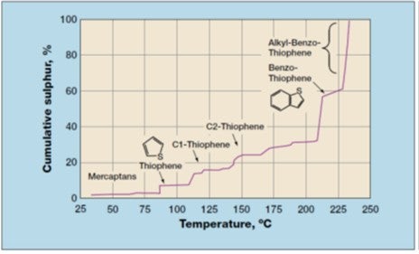
Within the context of producing ULSG, the primary role of CFHT is that of desulfurization and the impact on the FCC gasoline produced. If one were to target a ULSG pool sulfur level of 10 ppm, the CFHT must reduce the FCC feed sulfur to about 200-300 ppm, considering a typical ratio of between 20:1 and 30:1 of the hydrotreated FCC feed sulfur to the FCC gasoline sulfur. When looking at the sulfur in FCC gasoline, the gasoline cut point and the distillation tail on the produced gasoline product is of high importance. In the US market, gasoline has been traditionally over-cut relative to the standard 430°F (220°C) cut-point and often extended to 450-480°F (230-250°C), thereby including not only benzothiophene but also some methyl-benzothiophenes in the gasoline (Refer to Figure 1 - FCC Gasoline Sulfur Profile). By over-cutting, these more difficult sulfur compounds, which will remain at a significant level following CFHT, will subsequently find their way into the FCC gasoline and make it difficult to produce ULSG. Undercutting the gasoline to less than 430°F will significantly help control the sulfur level when producing ULSG.
Considering the dependence of FCC gasoline on both CFHT performance and the need for precise fractionation of the FCC gasoline product, meeting ULSG targets through CFHT alone is possible, but challenging. There is little room for error or deterioration in CFHT performance over the course of a production run or cycle. Further, there can be limited flexibility in crude slate, thus reducing the refiner’s ability to process opportunistic crudes. These deterrents along with the relatively high capital cost for CFHT coupled with low refinery margins have resulted in the wide application of FCC post-treatment to reduce FCC gasoline sulfur. In fact, many refiners with CFHT have found it necessary and/or economically advantageous to also have a post-treatment unit.
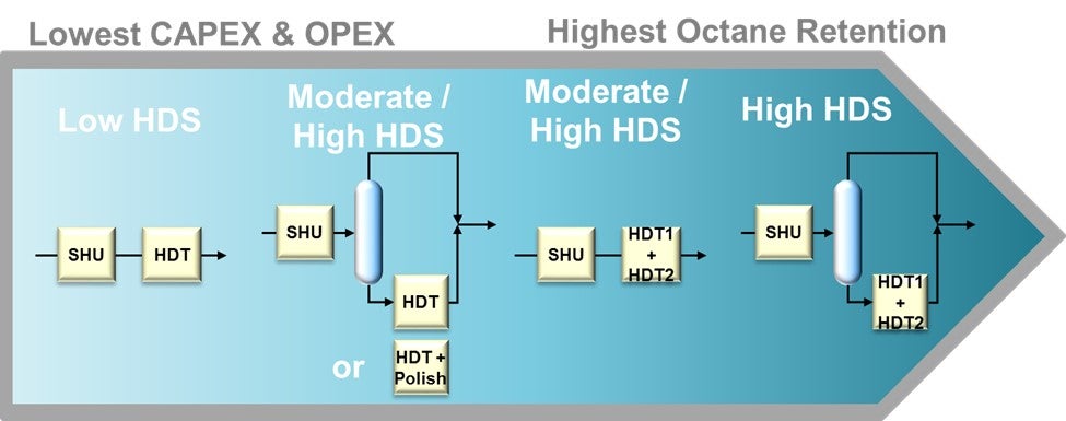
Most refiners have already invested in an FCC post-treatment unit. For a refinery with relatively high sulfur FCC gasoline, the post-treatment severity will be higher in order to produce ULSG (Refer to Figure 2 - Prime-G+TM Designs at 10ppm Product Sulfur). This higher severity can lead to an unwanted high-octane loss through the undesirable saturation of olefins in the post-treatment unit. However, depending on process technology and process flow scheme selected for the post-treatment unit, the concern over octane loss can be managed. Axens Prime-G+ process technology has been applied extensively with varying flow schemes (with corresponding varying capital cost investment) to produce USLG with an octane loss that is within the constraints of the refiner’s pool octane balance (Refer to Figure 3 - Prime-G+™ Tailored Scheme). In short, a simplified process flow scheme with a single reactor combining selective hydrogenation (SHU) and hydrodesulfurization (HDS) can be utilized when FCC gasoline sulfur is relatively low while yielding a very low octane loss. Conversely, a more complex process flow scheme with a SHU reactor, splitter, and HDS reactor can be utilized to treat a higher sulfur FCC gasoline while still minimizing octane loss to within the constraints of the refiner’s pool octane balance.
Figure 2 - Prime-G+TM Designs at 10ppm Product Sulfur
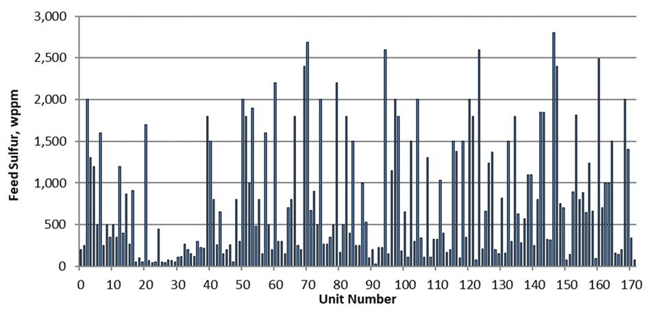
Figure 3 - Prime-G+™ Tailored Schemes
Where a refiner is producing ULSG through CFHT alone, the CFHT’s operating severity will be heavily dictated by the CFHT feed sulfur. In this scenario, if the refiner were to purchase a more opportunistic heavier and higher sulfur crude, there would be a resultant CFHT severity increase and a negative impact to the CFHT’s cycle length. Depending on the CFHT’s original design constraints, there may even be limits on what crude slate can be ran while still allowing production of ULSG. Similarly, with post-treatment alone, there would be an increase in post-treatment feed sulfur thus resulting in an increased severity requirement in the post-treatment unit. This would directionally have a negative impact on the post-treatment unit’s cycle length and would also result in a higher level of olefin saturation and corresponding octane loss. Having both CFHT and post-treatment, there is more potential to balance the overall higher severity requirement between both units thus having a lesser impact on cycle lengths and octane loss. Further, with both CFHT and post-treatment, through feed management and altered operating conditions, it may be possible to continue operations and production of ULSG while either the CFHT or post-treatment unit is off-line. Unfortunately, having both a CFHT and post-treatment unit comes at a high capital investment, and this can be a prohibitive barrier.
WENDY WILDENBERG (Flint Hills Resources)
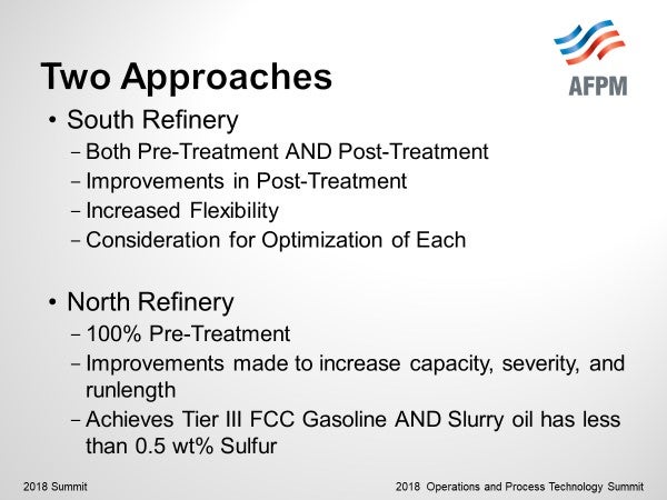
I can share two different approaches of use of hydroprocessing to meet Tier III regulations within the Flint Hills refineries.
A southern refinery has both an FCC Feed hydrotreater as well as an FCC Gasoline hydrotreater. Upgrades to the gasoline hydrotreater have been made in the last several years to achieve higher capacities and severities to lower sulfur levels in gasoline. The FCC Feed Gasoil hydrotreater has a lower severity, may hydrotreat 40 to 90% of the FCC Feedstock – and may even be bypassed if gasoline hydrotreating can be increased for lower opportunity cost maintenance as needed. Attention is necessary to balance the severity of the pre-treatment and post-treatment as Jeff mentioned to balance yield, severity, and runlength of the FCC Pretreater with olefin/octane loss of the post-treater. Feedstocks can be chosen to be processed in the Gasoil hydrotreater to maximize yield of the GOHT/FCC combined while allowing the easier feedstocks to feed the FCC directly.
Prior to the Tier II regulations, our northern refinery was already hydroprocessing 100% of the FCC feed to meet environmental emissions targets as well as for the increased LV yield. Severity increases were necessary to meet the lower sulfurs of Tier II and Tier III since the FCC gasoline is not further processed before gasoline blending. Improvements in catalyst activity were beneficial to lowering start-of-run temperature as well which is very helpful to increase runlength. Established guidelines and attentive monitoring for key parameters such as feed line-ups, hydrogen recycle rate, hydrogen purity, and temperature adjustments allow this refinery to process a large concentration of opportunity feedstocks and achieve longer runlengths (3-4 years). In this refinery, not only is the FCC Gasoline octane maintained without further processing, but the slurry oil sulfur has been < 0.5 wt% for the last several years.
GEORGE HOEKSTRA (Hoeskstra Trading LLC)
Hoekstra Trading sponsored a three-year program of pilot plant testing, catalyst testing, field testing, and market analysis, all aimed at answering the question, “How much octane will be destroyed when post treating severity is increased to make Tier III gasoline?”
The answer from our pilot plant testing is displayed in what we call the post-treater “performance curve” which is a chart of octane versus product sulfur:
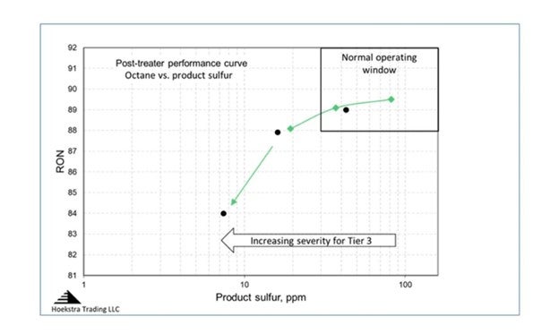
In this chart, post treater reaction severity is being increased as you move from right to left. As severity increases, gasoline sulfur decreases, and so does octane. This feed is from a US refinery, it is a full-range FCC gasoline with 443 ppm sulfur that has been pretreated in a diene saturator. The green and black data points are for two different catalysts. The normal operating window for post-treaters has historically been in the upper right region of the chart where the curve is flat, meaning little octane is lost as you increase severity to decrease product sulfur; but now, we are moving left into a new operating region for Tier III gasoline where the rate of octane loss accelerates. The acceleration is much higher than the industry expectation which says that octane will go down by 0.5 RON when severity is increased to make Tier III gasoline. Our pilot plant data shows it is much higher than that, which was an important new finding in 2015.
The next step was to see whether this important finding holds true in commercial post-treaters in North America. Our client group has run detailed chemical analyses on post treater feed and product samples from field tests on eleven commercial FCC gasoline desulfurizers. The results confirm our pilot plant findings — commercial post-treaters also lose 5 octanes when severity is increased to make Tier III sulfur gasoline.
Not all refineries will lose 5 octanes, only those that are not well-equipped to make Tier III gasoline reliably and profitably. The octane loss in each case depends strongly on the configuration of the FCC process train, the design of the post-treater, and the composition of the raw FCC gasoline. We have seen octane loss over 10 on some commercial units. It is highest for units that have no FCC pretreater and that run heavy, high sulfur feeds.
This chart shows how the performance curve will change for one refiner who decided to add a splitter to his post-treater for Tier III gasoline.
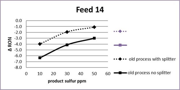
The dashed curve shows, at 20 ppm product sulfur, the octane loss will be 3 with the new splitter, compared to 5 (solid curve at 20 ppm) today.
These curves can be shifted up by cutting heavy tail out of the post treater feed. This chart shows the performance curve in the form of a spreadsheet model that is being used today by refiners and process licensors to estimate and optimize post treater performance for different feeds, process designs, and operating strategies. The dashed curve shows that, with a splitter and endpoint cutting, octane loss can be reduced to 2 RON (dashed curve at 20 ppm sulfur).
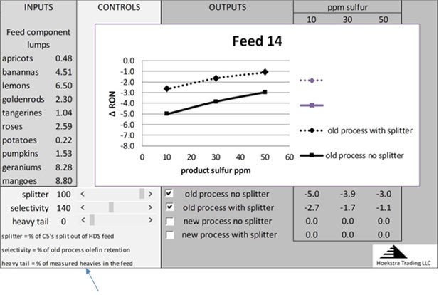
The controls at the bottom left of the worksheet permit varying the splitter efficiency, the heavy tail percentage, and the process selectivity to see the effects on the performance curves.
It is possible, with new catalysts and processes, to improve sulfur/octane selectivity by as much as 40% from historical levels. The purple curves show this effect:
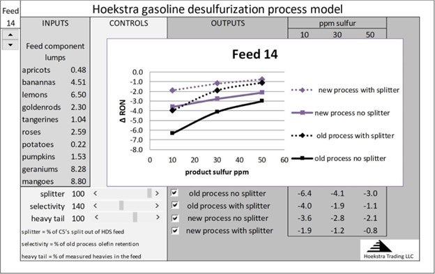
This full range of process improvement is available to refiners today through improved process design, catalyst selection, and feedstock management.
These curves are calculated accurately for any unit by entering the analytical data for that unit’s feed into the spreadsheet model. The model uses reaction rates that have been measured in pilot plant and commercial field tests on real feeds over a wide range of conditions.
The spreadsheet model and all the pilot plant and commercial test data are available to anyone for a small fraction of the cost of this work, which has been done by our client group over the last 3 years.
Year
2018
Process
Question 13: What factors do you consider when co-processing jet fuel in a distillate hydrotreater versus processing the jet separately (including feedstock and unit consideration)?
ROBERT STEINBERG (Motiva Enterprises)
There are several considerations when deciding if jet fuel and diesel should be co-processed or hydrotreated separately. The most important consideration is if the jet fuel will be blended into the diesel product or if separate products are desired. The decision may depend on if you are looking at constructing new facilities or making the best use of existing equipment.
If a refiner needs to build a new unit to increase distillate hydrotreating, building a jet fuel unit and using existing units for diesel will normally be less expensive than building a new diesel hydrotreater. If more capacity is required than there is jet fuel for, some straight run diesel can be blended into the jet fuel hydrotreater. However, if the existing unit is too low a pressure to handle the diesel effectively it may be preferred to build a new unit for the most difficult to treat streams such as light cycle oil or light coker gasoil instead.
If a new refinery was being built and new jet fuel and distillate hydrotreaters are needed it will normally be simpler and cheaper to build a single unit and co-process the jet fuel with the diesel. Exceptions would be if the capacity would be too large for a single unit or separate jet fuel and diesel products were desired.
For a refiner looking to optimize existing facilities it is assumed that a separate jet fuel product is not required. If it was required, the feeds would need to be processed separately unless there was a fractionator on the back end to make jet fuel and diesel cuts. Having such a fractionator is probably unusual and would require a lot of energy to vaporize the jet fuel to remove it from the diesel. For a refiner with only a single hydrotreater this becomes a question of batch processing diesel and jet fuel or blending them and processing together. If the refiner has multiple hydrotreaters it will generally make sense to send the easiest to treat streams, such as jet fuel, to the lowest pressure or mildest hydrotreater. Or blend just enough of the easiest streams into the more severe unit to let it achieve its desired run length.
Alternately batch processing jet fuel and diesel in the same unit instead of co-processing would generally not be recommended unless there were special circumstances. This would be more complicated as it would require frequent switching of feeds and changing operating conditions; during such changes lower charge rates may be needed to reduce the risk of making off-spec products or having to pull more naphtha out of the Stripper than otherwise required to maintain product flash point.
Diesel requires more severe reactor conditions than jet fuel to make the same product sulfur. Mixing jet fuel into the distillate hydrotreater lowers the average boiling point of the feed as well as the feed sulfur and nitrogen content. This means lower reactor temperatures and less chemical hydrogen consumption, less treat gas is needed to maintain the desired ratio of hydrogen availability to consumption, smaller exotherms and less quench gas. The lower start-of-run temperature can extend the catalyst run length.
Pressure drop for jet fuel and diesel in the same hydrotreater would be similar if the same amount of hydrogen circulation was used – more of the jet fuel would vaporize and increase velocity but the diesel has more mass at the same barrel per day charge rate and is more viscous. However, less treat gas is needed for jet fuel due to the lower chemical hydrogen consumption and exotherms are generally low enough with jet fuel to not need any quench. This effectively means less hydrogen circulation with jet fuel and lower pressure drop in the reactor, exchangers and furnace. Blending jet fuel into the diesel hydrotreater will reduce pressure drop, if the run length is limited by pressure drop this can extend the catalyst life.
Another consideration can be product blending and diesel cetane. If there are multiple units, or jet fuel and diesel are batch processed, some of the products may not meet sulfur, cloud point, cetane or other product specs. In some cases, the products from different units can be blended to make an on-spec ULSD. This makes operations more complicated, adjusting the amount of jet fuel that is blended into each unit can help keep all products on-spec and reduce the risk of having to deal with an off-spec product tank. However, jet fuel has a lower boiling point than diesel and thus a lower cetane number. If a refiner makes both a higher and a lower cetane product it may be necessary to minimize the jet fuel in the high cetane product, this is like making a separate jet fuel product in that it can require separate processing.
Motiva has a relatively mild hydrotreater than was revamped for ULSD 15 years ago. Initially it charged mostly straight run diesel to make ULSD. Later, the refinery was expanded, a new diesel hydrotreater was built and the additional jet fuel was charged to this unit. The unit now charges only jet fuel and operates in ultra-low sulfur kerosene (ULSK) mode, the product has less than 5 ppm S and can be blended into either jet fuel or diesel as desired. The unit has minimal catalyst aging. It illustrates that jet fuel can be the easiest product in the refinery to hydrotreat giving very long catalyst life and that adding jet fuel to a diesel hydrotreater results in milder reactor conditions and longer catalyst life.
Motiva normally produces more kerosene in our crude units than we have capacity for in our jet fuel hydrotreaters. The surplus kerosene is mixed into our diesel hydrotreaters. This is the easiest feed the diesel hydrotreaters process, with more kerosene reactor temperatures can be lowered while maintaining product sulfur. While this reduces the required reactor severity there are some drawbacks:
-
The lighter feed reduces the delta API gravity between feed and product meaning volume swell is reduced.
-
The lighter feed reduces the density of the feed going through the charge pump and the discharge pressure that the pump can produce. One of the diesels hydrotreaters sometimes needs to lower operating pressure to maintain charge rate.
Motiva normally hydrotreats as much kerosene as there is capacity for in our jet fuel hydrotreaters and blends the remaining kerosene into diesel hydrotreaters. One of the jet fuels hydrotreaters swings between sending its product to jet fuel and diesel but operates to be on-spec for both products. We do not have any units where we switch feeds or operating conditions to sometimes make jet fuel and sometimes diesel.
JOHN KULACH (UOP)
Considerations for co-processing jet and distillate in the same unit are the feed rates and feed quality, which go into the selection of operating pressure, space velocity, and catalyst. Distillate hydrotreating for ULSD typically requires higher hydrogen partial pressure, lower LHSV and more active catalysts compared to treating jet, because of the need to convert stable sulfur compounds such as benzothiophenes and dibenzothiophenes. If the distillate feed includes coker gas oils, LCO or other difficult to process streams such as extracts and condensates, the design would call for a more severe operation with higher reactor temperatures. Inorganic contaminants such as silica and arsenic can be removed from the feed upstream of the active desulfurization catalysts by using filters, particulate traps, and demetalization catalysts in the top of the reactor.
Jet hydrotreating requires enough catalyst and hydrogen partial pressure for mercaptan sulfur and TAN removal. This is usually a low severity operation compared to distillate hydrotreating as jet fuel can be very color sensitive exasperated by high reactor temperature operation. On the other hand, jet fuel hydrotreating can require more severe operation if the feed contains high aromatics or naphtenes which will require some saturation to meet composition and combustion specifications such as aromatic content and smoke point. In some cases, this might require a noble metal catalyst or a second stage operation.
While a typical distillate hydrotreater fractionation section would consist of a stripper column to remove light ends and meet flash point specification, a hydrotreater co-processing distillate with jet feed would require a more complex fractionation section. The fractionation configuration would depend on the relative rates of distillate and jet as well as the need to meet jet fuel volatility and fluidity specifications such as distillation and freeze point.
Whether a co-processing unit is more economical than individual DHT and KHT units will depend on the relative feed rates, feed quality and product specifications. Co-processing might be favored if the DHT feed is relatively easy (such as a SR Diesel) and if the jet feed is more difficult to treat. The key take-away is that jet fuel processing is very dependent on the feed quality and required specifications.
RICHARD TODD (Norton Engineering)
Co-processing of Jet Fuel in a distillate unit may result in poorer unit performance than expected due to higher vaporization of the jet fuel components, which in turn causes lower H2 partial pressure. This varies based on unit conditions, partial pressure of H2, LHSV, etc. The heavier distillate desulfurization is normally controlling, so reactor temperatures are set by the distillate requirements. Cracked stocks in the jet fuel range may have higher olefins increasing H2 consumption, and again in turn, decreasing H2 partial pressure, causing an increase in deactivation.
Year
2018
Process
Question 14: In your experience, what operational factors contribute most to utility costs in hydrotreating units?
ROBERT STEINBERG (Motiva Enterprises)
The biggest contributor to utility cost per barrel in a hydrotreater is probably the unit operating pressure. Higher pressure units require more energy to pump up the charge, hydrogen, amine and wash water.
The utility cost that may get the most attention and that operations has control over is heater firing. Use of a hot separator and bringing in hot feeds can substantially reduce heater firing. However, fired duty per barrel of charge is generally much lower for a hydrotreater than for many other refinery units like crude units, cokers and reformers.
Some people like to keep H2 to oil ratios to the minimum required for the catalyst even if they can circulate more. While this will save some energy, it may not be optimal for the catalyst. Using more than the minimum required recycle gas will increase H2 partial pressure and may reduce catalyst aging rates, it can also improve distribution within the catalyst bed. If catalyst life is extended, yields are improved, or product properties are improved the benefits can be much larger than the energy savings from the minimizing H2 to oil ratio. In addition to the catalyst benefits, higher recycle gas rates will increase velocities in exchangers and furnaces and may reduce fouling.
Some hydrotreaters maintain the same charge rate all the time using product recycle to maintain reactor feed if less fresh feed is available. It is necessary to maintain reactor charge rates high enough to be within the operating range of the distributor tray. If there are large amounts of cracked feeds, recycle can be needed to control exotherms. Maintaining the same charge rate can simplify operations, reduce exotherms and improve distribution within the reactor without impacting required reactor temperature or catalyst aging rate. However, it can also substantially increase energy consumption. For a short-term reduction in charge rate, such as for a few days, the simplicity of maintaining operating conditions may justify the recycle. For longer time periods, such as several weeks, the impact should be evaluated more carefully to see if more recycle than needed to maintain minimum charge rates is justified.
Using more than the minimum recycle gas rate can often extend catalyst life at the cost of a marginal increase in energy consumption. Using excess product recycle will often have little benefit and substantially increase energy consumption.
If there are advantages to using more than the minimum recycle gas or product recycle, the benefits such as better catalyst performance and simplicity should be compared to the extra energy cost to maximize profitability.
Year
2018
Process
Question 10: What are the problems with low coke operation in CCR reforming and how is it managed?
CHRISTIAN ARNOUX (Valero)
The opinions expressed are those of the author and do not necessarily represent the views of Valero Energy Corp.
Low coke regenerator operation became a significant issue after the adoption of the
10% ethanol in gasoline regulation which lowered the gasoline octane required from the refinery. At 10% blending ethanol raises the (R+M)/2 octane of regular gasoline about 2 numbers.
Low octane operation requires less catalyst regeneration and has changed operation of several CCR units to on/off regenerator operation:
-
The regenerator shuts down automatically on low air flow to the drying zone electric heater
-
On/off catalyst circulation is better than continuous un-regenerated catalyst circulation
-
During periods of not regenerating catalyst, activity loss of 10 to 20 deg F might be seen
-
There are some strategies for low coke operation that your licensor can help with
VIVEK GHOSH (UOP)
UOP does not have a fixed low coke limit for the design of CCR Platforming™ Continuous Catalyst Regeneration (CCR) sections. The low level of coke at which the normal operation of the regenerator will be constrained will vary depending upon the style of the regenerator and the individual unit.
Atmospheric Units: Major constraints would be low flow air control, lower air flow through the Air heater, insufficient catalyst drying and reduced O2 in Chlorination Zone which will eventually affects the platinum dispersion on catalyst.
Cyclemax Units: There are several constraints that define the low coke limit and they are unit specific such as, for units with Chlorsorb™, the ability of the thermocompressor to provide recirculation gas through the air heater preventing it from low flow trip or the ability to provide sufficient recirculation gas to cool the catalyst in the cooling zone when the catalyst circulation rate is high while the coke on catalyst is low and the controllability of the regeneration gas vent control valve.
Managing low coke operation: There are two ways refiners can approach low coke operations; increasing unit coke make or adjusting the regenerator operation to burn less coke. Unfortunately, in most cases units have little control over trying to increase their coke make. The “typical” ways to try to
increase coke on catalyst are as follows:
-
Increase feed rate
-
Increase octane
-
Leaner feed PONA (more paraffinic)
-
Higher feed endpoint
-
Lower average reactor pressure
-
Lower reactor H2/HC
This list may look like there are many options, but a refiner may not have control over many of these items. Typically feed rate, target octane, and PONA are dictated by the planning department and cannot be easily changed. The engineer can request a higher feed endpoint but that is subject to refinery economics and is only adjustable up to a certain point because it can affect reformate endpoint and color. Lowering the average reactor pressure significantly would likely require a unit revamp. The best tool an engineer has to increase coke make is to reduce the recycle gas H2/HC ratio. This will also have an added benefit of utilities savings (lower compressor load). However, there may be a low limit on the compressor flow rate based the flow rate required to properly distribute the liquid feed in the Combined Feed Exchanger.
The area where the refiner has more options to manage low coke operations is on the regenerator side. CCR Platforming regenerators are designed to burn catalyst with 5.0 wt% carbon at the design circulation rate. The low side of the design range is approximately 60% of design coke load (about 3 wt% coke at design catalyst circulation rate) however, most regenerators can operate well below that 60% point with some able to maintain stable, normal operation at as low as 30% of design coke.
UOP recommends keeping the regenerator in continuous white burn operation for both utilities savings and proper reconditioning of the catalyst. White burn is the normal operating condition for the UOP CCR Platforming Process Unit regenerator. Continuous regeneration in white burn allows the air and chloride injection to be sent to the normal locations rather than the black burn locations.
Each style of CCR Platforming Process Unit regenerator has its own limitations in low coke operation, but the typical responses to low coke are as follows:
-
Reduce catalyst circulation
-
Provides additional residence time in the burn zone to reduce residual coke
-
Provides additional residence time in the chlorination zone to maintain optimal platinum dispersion
-
Increases residence time in the drying zone
-
Helps keep recycle gas moisture low. Lower circulation means less catalyst is being reduced
-
Reduce burn zone oxygen set point and monitor temperature profile closely
-
Vent more excess air, if possible
-
Maintain minimum air heater flow rate
-
Maintain enough drying air flow
Please contact your UOP representative for specific information related to the potential limiting factors for your style of regenerator and responses to low coke operation. For example, for atmospheric units, there is a low coke revamp option of adding vent line from the Chlorination loop, which allows adding excess air, removing the air heater and catalyst drying limitations and helps to maintain a higher O2 concentration in the Chlorination Zone.
What if your coke make is extremely low?
In some instances, Platforming unit coke make is so low that it is not practical to keep the regenerator running in white burn. In this case, it is recommended that the catalyst be continuously circulated until enough coke is laid down to restart the regenerator.
JESUS PEREZ (Alfa Laval Packinox)
Low coke operation might require shutting down the regenerator for periods of time. To avoid this disruption, some Refiners lower the H2/HC ratio so that there is some minimum coke production which can keep the regenerator continuously operating. This solution has a direct impact on the Combined Feed Effluent exchanger’s performance since proper liquid lift is compromised whether the exchangers used are Texas Towers or the high efficiency Packinox heat exchanger.
Alfa Laval Packinox has developed a liquid lifting monitoring tool to detect insufficient lifting of the liquid, based on an estimate of the required minimum recycle gas flow rate and temperature and pressure drop measurements. By using this tool, the refiners can safely push the limits of the Packinox exchanger operation while still achieving high energy efficiency.
GAYL MERCADO (Axens North America)
Refiners in the US have been operating reformer units at low severity due to ethanol blending in the gasoline pool. Operating the CCR at a lower severity provides higher reformate yields but can also become an issue in the Regenerator if coke levels become too low. With low coke operation, it is difficult to initiate coke burning and to maintain a good thermal balance in the Regenerator to achieve optimal regeneration conditions. If the entire amount of coke is not burned off at the bottom of the burning zone, coked catalyst will enter the oxychlorination with a high oxygen content and uncontrolled burning will occur. When coked catalyst is present in the oxychlorination, the oxychlorination gas, water and air injections that are necessary to restore the chlorine content on the catalyst and re-disperse the metal phase are completely stopped in the Regenerator. Consequently, catalyst that has not been fully regenerated returns to the reactors with a lower catalyst activity. Refiners usually will have a difficult time to optimize regenerator conditions that are required to achieve full catalyst regeneration and regain catalyst activity.
Axens has assisted with managing low coke operation by adjusting unit operations to help promote coke-make in the CCR. These recommended operational changes are highlighted below.
-
Stop catalyst circulation rate
-
Lower H2/HC ratio
-
Decrease system pressure
-
Recycle reformate product
-
Increase Feed EBP
-
Inject small amount of kerosene or diesel
Low coke operation may be less of an issue for refiners in the future as octane demand is expected to increase due to higher octane demand in the gasoline pool
Year
2018
Process
Question 11: What constitutes adequate quench reserve when you process cracked feedstocks in hydrotreating units? In hydrocracking units? What if a mixture of both gas and liquid quench is used?
WENDY WILDENBERG (Flint Hills Resources)

We will start out this session on Hydroprocessing with an analogy to begin to provide the answer.
Have you ever watched a child walk a dog? Maybe a big dog?
The dog may be obedient and staying with the child for a while – as long as the dog wants to go the direction that the child is leading. The child has the illusion of being in control of the dog.
But if the dog gets distracted – say by a passing squirrel – the dog may take off and hurt the poor child.
Maintaining control means that the dog walker – needs to be able to hang on to the dog – even if it starts to walk or run away. This takes adequate reserve strength - and an early detection and response when the dog just begins to become distracted or when we begin to feel the pull on the leash.
Same with a hydroprocessing reactor. We need to maintain enough recycle hydrogen to provide sweeping of the oil and cooling of the heat of reaction. We need to provide adequate reserve cooling to handle the size of the reactor duty that we allow. Hydrocrackers are big dogs – and ready to pull away and run. Hydrotreaters will walk away until the temperature reaches Hydrocracking temperatures (>800°F).

At that point – we have the increased duty of a Hydrocracker running away – we have measured accelerating at over 10°F per second increase. This slide shows the acceleration measured on a highly active zeolite cracking bed when the quench was decreased by a faulty temperature indication.

Hydroprocessing Units therefore need reserve cooling and good detection and control to be able to regain control of a reactor and stabilize the temperature in case of higher heat of reaction. One addition of increased heat of reaction is more feed olefins. A unit that has more coker feedstocks, with swings or increases in these olefinic feedstocks will require higher reserve cooling duty to compensate than a virgin hydrotreater that has hardly any change in exotherm from feed changes.

A simple definition of a temperature excursion is that the Heat of Reaction is increasing at a rate faster than the ability to increase cooling to balance the reactor. Unlike our dog story – our reactors increase in size of reaction duty as they increase in temperature. It is harder to regain control once they start to get away.

Several causes of increased heat of reaction for your unit during normal operation need to be considered when determining the amount of reserve cooling or quenching.
-
INCREASE in Cracked Stock (increase in olefin and aromatics)
-
INCREASED TIME in REACTOR (partial loss of feed or reduced feed rates)
-
INCREASE in reactor temperature (planned or unplanned like heater over-firing)

Considerations for Hydrotreaters vs. Hydrocrackers:
Differences between Hydrotreating and hydrocracking (catalyst contains acid function) exist that must be accounted for in determining where to maintain reserve quench and determination of safety interlocks / response.
Hydrotreaters can have temperature excursions, but there are a few other factors to consider that allow reserve cooling to be applied in other areas as well or even instead of the reserve quench. Until the high temperature is reached, hydrotreaters will “walk away”. Therefore, reducing firing / tripping the heater fuel gas and stopping feed may stop the growing heat wave in time to prevent temperatures from exceeding design limits.
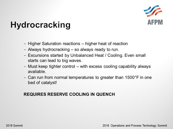
Hydrocrackers have higher heat of reaction from saturation reactions as the cracking function creates olefins that are then saturated. There are plenty of reactants available. Reactor catalyst beds with cracking catalyst must have the ability to apply reserve cooling directly to the bed as well as the ability to cool from upper beds. We have witnessed from a sudden loss of quench, hydrocracking beds rising from normal temperatures to > 1500°F in that bed.

Reserve quench hydrogen provides direct cooling to the individual bed for the fastest response and is required for all hydrocracking beds. Best practice for quench hydrogen is to measure the hydraulic capability and then hold 50% of that capability in reserve. Use caution if setting limits for normal quench on % opening of a control valve. If the control valve has equal percentage trim, 70% open may be near 100% of hydraulic capability. Also ensure that the control system is designed to use the full capacity of the control valve, and not limit the valve opening based on the flow meter span.
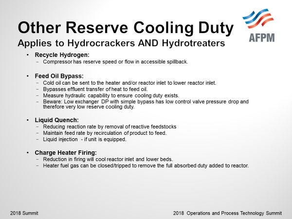
Other cooling knobs that may be applied to reduce the temperature of the reactor include Reserve compressor capacity, feed oil bypass, liquid quench (includes recirculation of product to feed) and reductions in charge heater firing.
Cold oil may be sent to the heater and/or reactor inlet by bypassing the feed/effluent heat exchange. To ensure adequate reserve is maintained, measure hydraulic capability with valve fully open to determine range of cooling available. Beware of the design of low exchanger train pressure drop with a simple control valve bypass. As the bypass control valve is opened, the driving force for flow through the bypass decreases leading to lower hydraulic capability for providing cooling.
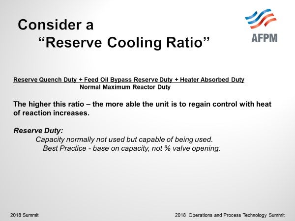
The higher this ratio, the more the unit is capable of regaining control with heat of reaction increases.
Reserve duty is defined as capacity not used for normal operation, but capable for use. Best practice is to set normal operational limits based on % of capacity, not on % opening of control valves.
An important point I need to share in case of recycle compressor failure, no reserve capacity for quench is available. Use Risk assessment in your units to determine procedural and safety interlock responses necessary.
Year
2018
Process
Question 9: Are you adding unusual feeds to catalytic condensation or oligomerization units?
GAYL MERCADO (Axens North America)
Refiners have been pursuing the use of more atypical feeds to their olefin oligomerization units for various reasons. Units have historically operated on FCC LPG cuts, but an interest to process Coker LPGs or even heavier FCC olefins have begun.
The use of these alternative feeds has historically been limited by several factors, but newer catalyst generations and types have allowed a wider envelope of feeds while maintaining stable operation with long cycle lengths.
Refiners have been looking to a propane/propylene (PP) cut to units processing heavier materials. As well, options to remove C5s from the gasoline pool through oligomerization to heavier material can make sense where refiners find themselves long on light material in the pool, ultimately reducing the RVP of final blend.
Within Axens, the oligomerization suite of technologies was developed around a single robust catalyst, that can operate in wide range of environments and with various feed qualities.

When operating with traditional FCC and Coker LPGs, the PolynaphthaTM focuses on converting into gasoline and middle distillates, providing an economical solution for refiners to tackle the unbalanced gasoline/middle distillates slates. When looking to maximize octane, the SelectopolTM technology targets conversion of only the isobutene portion of an olefinic C4 fraction to either produce a high octane, low RVP gasoline blending stock or to produce a trimethyl pentene stream for petrochemical applications. The enriched n-butene product is an ideal feed to an alkylation unit without requiring any pretreatment. Lastly, the PolyFuelTM technology expands on the operation of lighter cuts by the co-processing, or even direct processing of heavier olefins to produce a heavy gasoline and middle distillates at lower cost.
CHRISTIAN ARNOUX (Valero)
The opinions expressed are those of the author and do not necessarily represent the views of Valero Energy Corp.
-
An FCC Cat-Poly reactor will convert propylene and butylene into gasoline blending components
PAT BULLEN and JOCELYN DAGUIO (UOP)
UOP has not designed any units with feeds outside of C3/C4 range. We have heard from customers discussing adding C5 olefins and benzene to their existing Cat Poly units but have not received any data from this type of operation to evaluate its efficacy.
Year
2018
Process
Question 21: What are your important considerations for water washing with respect to: 1) Intermittent injection a. Process temperature of injection b. Duration of injection c. Frequency - triggers to begin d. How frequently before making it continuously? 2) Water Quality: a. pH range b. Oxygen c. Total Suspended solids d. Total dissolved solids e. Recirculation vs. make-up f. Other
WENDY WILDENBERG (Flint Hills Resources)
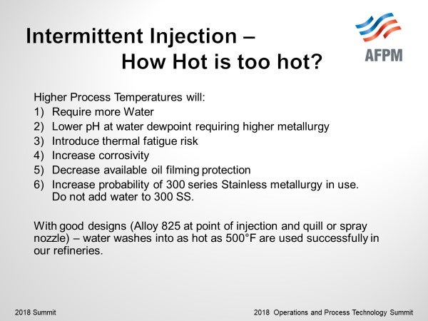
How hot is too hot for injection? Higher Process Temperatures will:
-
Require more Water to meet 25% Free Water at injection temperature. Injection of water that will all vaporize at the hotter temperature will guarantee that the droplets will form downstream and produce a corrosive mist prior to a well diluted stream. This may lead to aggressive corrosion where this occurs.
-
Lower pH at water dewpoint due to high solubility of HCl and low solubility of NH3. Recognition of this low pH may mean to consider higher alloy at the point of injection.
-
Increased thermal fatigue risk especially when greater than 300°F difference between water and upstream process temperature.
-
Increased corrosivity due to higher temperatures and typically lower liquid oil rates. Liquid oil has been shown to lower corrosivity.
-
Beware of Stainless-Steel Metallurgy that is more likely used at the hotter process temperatures. Do not inject water into stainless steel in order to prevent chloride stress corrosion cracking. All other components for this mechanism are already present except for liquid water.
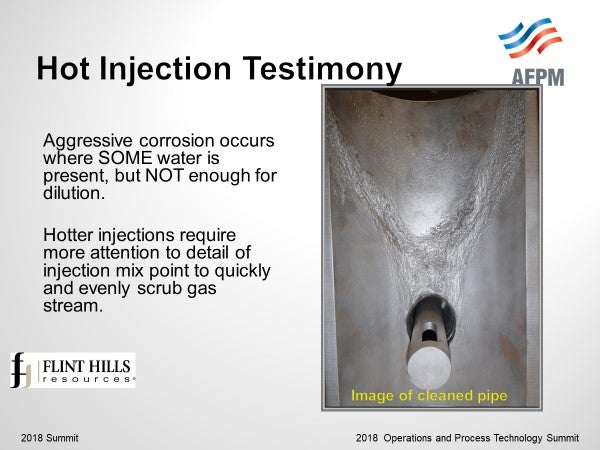
Hotter temperatures typically will increase in the need for better designed injection systems. The injection mix point needs to be designed to contact and scrub the vapor well, with adequate dilution of water, with metallurgy at the injection point selected to handle the lower pH of the droplets. The goal of this injection is to as quickly as possible contact the liquid water with the vapor to move all the chlorides from the vapor into the aqueous solution without leaving deposits behind as places for under-deposit corrosion. A good injection system is even more important at the higher temperature where increased potential for vaporization and hot/cold areas if poorly distributed may exist.
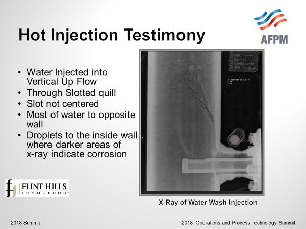
Lessons learned from a hot injection with a simple quill show what may happen with inadequate mixing / inadequate contact of the hot vapor with the water injection. This example shows a continuous injection of water with a slotted quill into vertical up-flow piping. An X-ray reveals several items: water comes out of the slot in a larger stream and directed with more flow toward the opposite wall. This slot was not centered in the piping. Droplets spray back to the inside wall above the quill. Infrared images show hotter temperatures above the quill on the inside wall and colder temperatures on the opposite wall confirming that more of the water flows to the opposite side. Corrosion is evident in between the hotter and colder areas and can be seen on the X-Ray. After this injection system was replaced with a better system (spray nozzle, static mixer, in an Alloy 825 section of piping), analysis of the removed piping allowed understanding of what this hot injection experienced.
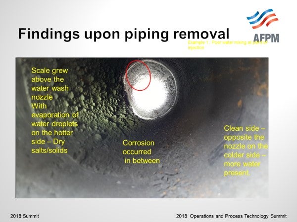
Scale formation was evident on the hotter section of piping. Vaporization of the stripped sour water left deposits of iron, iron sulfide, and other salt deposits on the piping. The opposite wall was clean and full metal thickness – this section was adequately water washed. But in between the dry area and the well washed cooler area, we found corrosion.
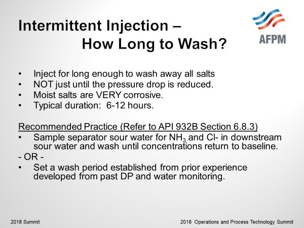
How long to intermittently wash? Duration of injection is typically 6-12 hours. Injection time is necessary to wash away all the salts which is longer than the time necessary for pressure drop to decrease too normal. If salts are not removed, the moist salts will increase corrosivity. Recommended practice is to sample the sour water for ammonia (NH3) and Chlorides (Cl) while executing the intermittent wash. Continue to wash until the ammonium salt levels decrease to baseline. As an alternative, documented results from previous washes can be used to establish duration of water wash. Audits are recommended to ensure conditions remain similar. Refer to API RP 932B, Section 6.8.3 for more information.
How long to intermittently wash? Duration of injection is typically 6-12 hours. Injection time is necessary to wash away all the salts which is longer than the time necessary for pressure drop to decrease too normal. If salts are not removed, the moist salts will increase corrosivity. Recommended practice is to sample the sour water for ammonia (NH3) and Chlorides (Cl) while executing the intermittent wash. Continue to wash until the ammonium salt levels decrease to baseline. As an alternative, documented results from previous washes can be used to establish duration of water wash. Audits are recommended to ensure conditions remain similar. Refer to API RP 932B, Section 6.8.3 for more information.
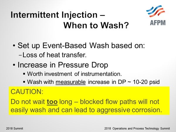
When to intermittently wash? Establish guidelines of when to wash based on loss of performance from exchangers. Loss of heat transfer is most often the earliest warning. An increase of pressure drop especially in the tube side of exchangers will also tell of the presence of salts. Shell side of the exchanger may take longer to show.
Recommendation is to wash when a pressure drop of 10-20 psid is measured, but not to wait too long until tubes become blocked.
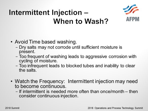
Avoid time-based washing. Dry salts may not corrode until enough moisture present. But too frequent of washing leads to aggressive corrosion. Watch the frequency of injection. If intermittent is necessary, more often than once per month consider reducing salts or making the injection continuous.
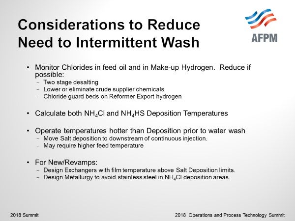
Consideration may be given to reduce the need to intermittently wash through changes to the incoming chlorides, changes to operational temperatures, and changes to new design or revamps. Most intermittent washes are washing ammonium chloride salts from upstream exchangers. Reduce chloride in feed oil and make-up hydrogen if possible. Two stage desalting and discussions with crude suppliers to lower chloride and/or bromide containing chemicals may aid in reducing oil sources. Chloride guard beds on reformer export hydrogen will reduce or eliminate chlorides in make-up hydrogen.
Calculate both ammonium chloride (NH4Cl) and ammonium bisulfide deposition temperatures and operate to maintain temperatures higher than deposition until the continuous water wash if possible.
For new designs or revamps, exchangers can be designed in order to plan for salt deposition downstream of the continuous water wash. Design exchanger trains with film temperatures above salt deposition in first exchangers with colder film temperatures downstream of the continuous injection. Also, exchanger metallurgy can be determined to avoid stainless steel in areas where ammonium chloride may deposit.
A few other cautions with intermittent water washing:
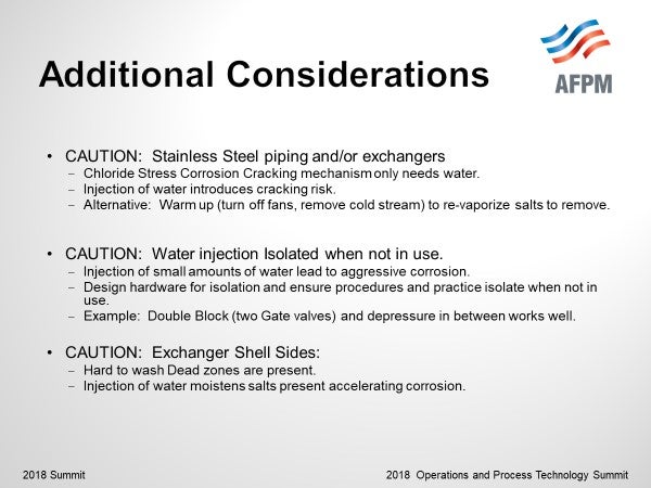
CAUTION: Stainless Steel piping and/or exchangers. Recommendation to not wash. Addition of water completes the recipe for stress corrosion cracking. Instead, consider warming up by removal of the cold stream or turning off fans if finfan to re-vaporize the salts to remove instead.
CAUTION: Ensure to isolate the water injection when not in use. The continued injection of small amounts of water leads to aggressive corrosion. Design hardware for isolation and ensure procedures and practices are in place to isolate when not in use. In our experience, a double block (two gate valves) with bleed to depressure in between works well.
CAUTION: Shell side water washing can be done, but hard to wash dead zones may be present. Additional water volume and longer wash times are recommended to remove salts.
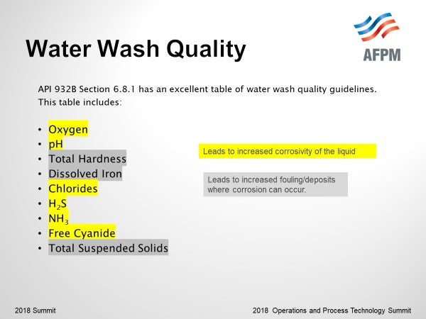
Water wash quality guidelines are well covered in API RP 932B and include limits on Oxygen, pH, Total Hardness, Dissolved Iron, Chlorides, H2S, NH3, Free Cyanide, and Total Suspended Solids with a description on the importance of each. Some of these factors increase the corrosivity, some increase fouling. Methods for water quality monitoring are important for your unit.
RICHARD TODD (Norton Engineering)
1a. Water wash rates are set by a variety of conditions, including at least 25% liquid water at the injection site, calculated by using the process conditions at the injection location.
1b. Intermittent injection should continue until the NH4Cl or NH4HS is shown to be removed by water testing for contaminants. It should not be set by pressure drop reduction as that can happen rapidly, while there are still salts to be removed.
1c. Intermittent wash water frequency should be set by delta pressure measurements, rather than on a time basis.
1d. If washes are required more than a few times a week, switching to continuous water wash should be considered.
2a. Water quality should be of stripped sour water or bfw/condensate composition, low oxygen, < 50 ppb, dissolved Fe, < 1ppm, and pH range of 7 to 9, TSS < 1, Cyanide <1 ppm. Recirculation should be determined by NH4HS, NH4Cl concentrations, and metallurgy. i.e., carbon steel requiring lower concentrations, along with % liquid water at the injection location.
JEFFREY ZURLO (Suez Water Technologies & Solutions)
Ammonia and halides in the reactor effluent will form corrosive salts as the it is cooled downstream of the reactors. Unless dissolved or dispersed, these salts can lay down in downstream equipment and result in fouling and under salt deposit corrosion, impairing production and reliability. Water washing the reactor effluent stream is an effective way to keep salts from fouling and corroding downstream equipment. Best practice is to provide the water wash continuously to ensure consistent washing of the piping/exchangers and prevent cyclical buildup of salts that can foul and corrode in between wash cycles. That said, water washing on a periodic basis can be effective, assuming the system is well designed, and the frequency is often enough to prevent equipment fouling and corrosion. The exact requirements for how frequently and how long to wash should be established on an individual basis as each system may react differently. The primary disadvantage of periodic water washing is creation of wet salts in the system, which generally increase corrosion rates as compared to dry salts or no salts.
Injection location should be upstream of salt formation temperature in the system and varies based on unit operating conditions and salt formation temperatures for the individual system.
One of the main considerations is to provide enough wash water such that there is enough liquid water present downstream of the water injection to dissolve and wash away the salts. Thermal and ionic modeling of the reactor effluent system can produce the required water volume and salt point temperature of the system to determine proper injection location and required water volumes.
Ideally, steam condensate or other source of water free of suspended solids, dissolved solids, and oxygen should be used. Poor quality wash water can result in adding to the solids deposition of the system, rather than cleaning the system of fouling materials.
Year
2018
Process