
Question 44: How is coke on catalyst in fixed-bed and moving-bed reforming units tracked? How is this data used to adjust the reactor inlet temperatures in order to maintain constant product octane?
PIZZINI (Phillips 66)
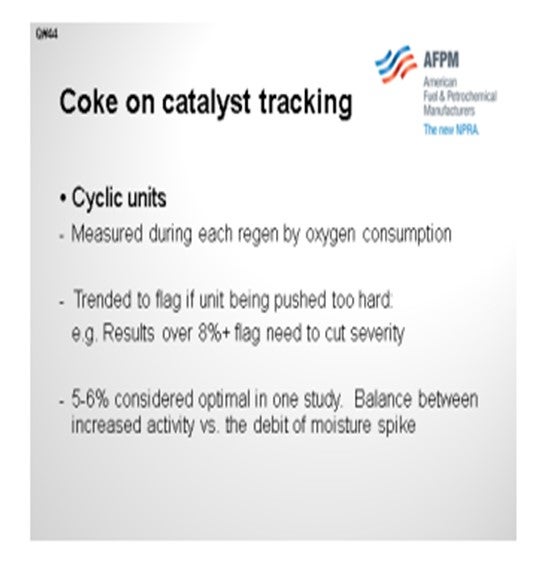
In our cyclic units, just based on the air consumption, we can measure the coke each time a reactor comes out for a regen. We are not grabbing samples. Our experience with the cyclics is that if you get up around 8% coke on catalyst, the unit will be pushed a little too hard. You will then need to think about backing it down on feed rate octane, finding a better-quality feed, or possibly increasing the hydrogen/oil ratio.
In one of our studies, we found that 5% to 6% coke on catalyst for a cyclic was just about optimal between the activity and the effect on yields. Every time we switch in a new reactor, we have a bump in moisture, resulting in more C4- until the unit dries out.
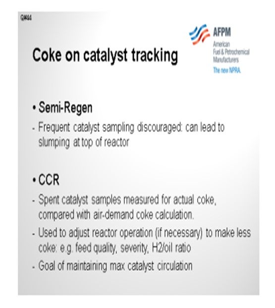
Where we could regen faster, we discovered that the optimum cycle was to allow 5% or 6% coke on catalyst. Some of our semi-regen vessels do have catalyst sampling options, but we actually discourage taking those samples frequently. The concern, of course, with a radial reactor is that you never want to uncover the top part because it could allow gases to bypass into the center downpipe.
The octane control on a semi-regen is just a matter of sending samples to the lab and tracking the octane. The purposes of the other components are to figure out the length of your run and manage feed rate and severity to make the run.
On CCRs, we do sample the spent catalyst directly for coke on catalyst. That number is compared with the calculated coke number, which is determined based on the air demand. Again, that number is used to track whether or not we are pushing the unit too hard. If it will be necessary to make less coke, then you could reduce the octane feed or increase the hydrogen-oil ratio. The goal is to maintain a maximum circulation of catalyst.
STEVES (Norton Engineering Consultants, Inc.)
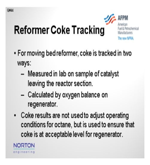
My experience and comments are about a moving-bed reformer or CCR. We track coke in two ways. As Paul mentioned, we take a sample of the catalyst and measure the coke in the lab. We also then calculate, by oxygen balance, the coke in the regenerator that is being combusted. We do not use the coke results to adjust the operating conditions for octane, but we do use it to ensure that the amount of coke entering is within the coke burning capability of that
regenerator.
I have seen coke prediction spreadsheets used to estimate the coke being made on the catalyst when the regenerator section is taken out of service for maintenance or screen cleaning. With that spreadsheet tool, we evaluate multiple cases to determine the impact of feed rate octane and feed quality on the coke levels to ensure that the coke stays below the maximum target levels before the regenerator is returned to service.
PATRICK BULLEN (UOP, A Honeywell Company)
For CCRs, we recommend that you do weekly sampling of the coke in your unit’s local lab to make sure that you are at the right point for your calculations and that you then make adjustments as needed.
PIZZINI (Phillips 66)
On fixed-bed cyclic units, the coke on catalyst is quantified on each reactor when it cycles out for regeneration. This information is mainly used to identify if the unit is being pushed too hard with respect to rates, octane, and H2/oil ratio. Experience has shown that coke on catalyst greater than 8% may indicate a coke-imbalance which will require a rate cut to hold constant octane. A study on one of our cyclic reformers showed that a regeneration frequency that averaged 5% to 6% coke on catalyst provided the optimal yields and activity. For that unit, regenerating too often caused a drop in average C5+ and H2 yields due to the moisture spike that results when each reactor comes back into the process from regeneration. Otherwise, RITS are adjusted “as needed”, based on daily octane results.
On one of our CCRs, we measure actual coke on spent catalyst to validate the air-demand coke calculation. Both readings are used to adjust reactor operation if necessary to make less coke (e.g., feed quality, severity, feed rate, H2/oil ratio) with a goal of maintaining maximum catalyst circulation. Catalyst samples are also used for chloride adjustment.
On our semi-regeneration reformers, we discourage frequent catalyst samples to test for coke content because over time the loss of catalyst increases slump and causes bypassing at the top of the reactor. This can affect reactor performance and lead to catalyst fluidization and attrition.
SUBHASH SINGHAL (Kuwait National Petroleum Company)
In CCR units, the coke in spent catalyst is analyzed, and regenerator conditions are adjusted to achieve the target coke level in the regenerated catalyst. Constant octane is maintained by adjusting reactor temperature, preferably flat profile.
Process
Question 45: What is the maximum allowable limit for the iron content of a reforming catalyst? Is this limit the same for semi-regenerative and continuously-regenerative catalysts?
DUBIN (Axens North America)
We have seen that the maximum allowable iron on catalyst cannot be reduced to a simple number. Historically, about 3,000 wppm is the level at which we see yield start to suffer, but not every wppm of iron has the same impact on the unit. Iron deposited on the surface of the catalyst, usually from corrosion-related byproducts, tends to have less of an impact on the overall performance. Some units have tolerated quite a high level of iron as long as the iron stayed on the surface of the catalyst bead. However, if the iron is able to migrate into the center of the catalyst bead, then the quantity needed to hurt yields could be much less than the 3,000 wppm I noted earlier.
As the iron migrates, we see the larger iron species hindering redispersion during regeneration. The yield penalty seen from this loss of redispersion mirrors that of a decreased metallic function for a given octane. Higher inlet temperatures are needed to meet a given octane, and subsequent loss of reformate is observed.
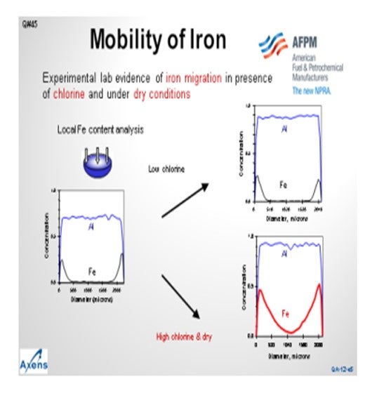
This slide shows a microprobe analysis of catalyst moving inward from the outer surface of the catalyst. You can see that the alumina is distributed uniformly throughout the catalyst particle. The iron concentrates on the outer surface of the bead, but we see that very little of it has migrated to the core. Under what we would consider low chlorine conditions, or sufficiently moist conditions, the migration of iron is mitigated. However, under higher chlorine content or drier reaction zones, the iron movement can increase and migrate into the center of the bead, leading to reduced yields. We consider a high chlorine environment to be 1.2 wt% to 1.3 wt% chloride on catalyst and dry being less than 10 wppm moisture in the recycle gas. Note that moisture tends to inhibit the migration of iron into the center of the bead.
Getting to the second aspect of the question about the allowable limit of iron on catalyst, we use the same limit on iron for fixed-bed and moving-bed reactors; however, the impact is not quite the same. For moving-bed reactors, the iron is distributed evenly across the catalyst due to the nature of the catalyst circulation, whereas in fixed-beds units, all of the iron deposit is in the first reactor. If the first reactor catalyst is sufficiently poisoned, the reforming reactions will move into the second reactor, and so on. However, it is difficult to play catch-up with the reforming reactions due to the endothermic nature of the reaction. Long term, it is hard to catch up on octane with a poisoned first reactor. For cyclic units, we have seen that the poisoning of the first reactor is essentially the same as a fixed-bed unit. However, with the swing reactor present, you have the ability to change out the first reactor catalyst if the catalyst underperforms
for whatever reason.
PIZZINI (Phillips 66)
It is really just a practical consideration regarding iron. We had a semi-regen unit that had to shut down, drop screen, and reload the first reactor without the benefit of a coke burn. We had removed most of the catalyst and were down to just the dust and fines. We then experienced a dust collector event on the vacuum truck. The dust contained pyrophoric iron since it had not been through a burn. In this case, the vacuum truck was set up with a nitrogen purge. However, the investigation showed that the truck did not have enough nitrogen purge. So just keep in mind that the iron can be pyrophoric, even on a reformer.
PATRICK BULLEN (UOP, A Honeywell Company)
UOP agrees with Axens that the situation is complicated.
DUBIN (Axens North America)
The maximum allowable iron content on catalyst cannot be reduced to a simple number. Historically, we have seen that at approximately 3,000 wppm, the impact on yields from iron starts to become significant. However, every ppm of iron on the catalyst is not equal in its effect on the unit. Often, iron that has deposited on the surface of the catalyst, typically from corrosion-related byproducts, has a limited impact on the overall performance of the catalyst. In several
instances, we have seen that the catalyst was able to tolerate high levels of iron while still performing at or near the expected level of conversion.
The quantity of iron needed to cause deterioration in the performance in certain circumstances can be well less than the 3,000 wppm mentioned earlier if the iron migrates to center of the bead from the outer surface. We have experience with a client who saw a decrease in performance at a lower content of iron on the catalyst. However, a significant portion of the iron in this situation had migrated to the center of the bead. As the iron migrates to the center of
the bead, platinum becomes less accessible as the larger iron molecules – e.g., FeS (iron sulfide)– plug the pores of the catalyst. The yield penalty observed during an iron poisoning situation mirror that of loss of metallic function. Higher average bed inlet temperatures would be required to compensate for the lost metallic function leading to decreased C5+ yields.
In Axens’ view, the iron contamination limit for semi-regeneration and continuously regenerative catalyst are the same, but the long-term operation with high iron catalyst is not. As the iron in the feed is distributed across the continuously regenerated catalyst evenly, the impact can be lessened or even delayed due to the catalyst circulation. For a semi-regeneration unit, the sulfur will accumulate on the first bed, potentially killing the activity of the first bed before the iron would theoretically migrate to the second bed; ‘theoretically’, because not many refiners would be able to maintain reformate production at an acceptable level with the long-term poisoning of the first reactor. Even moderate poisoning of the first bed in a semi-regeneration unit is a concern as it is unrealistic that a refiner can play ‘catch-up’ in subsequent reactors to meet the desired conversion due to the nature of the reforming reactions. Cyclic operations suffer from the same overall concerns as a semi-regeneration unit, but with a swing reactor present, the unit has the ability to replace catalyst on the fly when the yield penalty from poisoning is no longer acceptable.
PIZZINI (Phillips 66)
P66 also experienced a catalyst unloading issue related to pyrophoric iron on a lead reactor which had to be dropped and screened in an unburned condition. The presence of iron led to a vacuum truck dust collector event when vacuuming fines from the lead reactor. This was found to be the result of insufficient N2 purge on the vacuum truck.
Year
2012
Process
Question 46: Are refiners modifying the operating conditions in reforming units, for example, chloride on catalyst, in order to capture margin differences between natural gas, used as fuel, and liquid products?
KOONTZ (HollyFrontier)
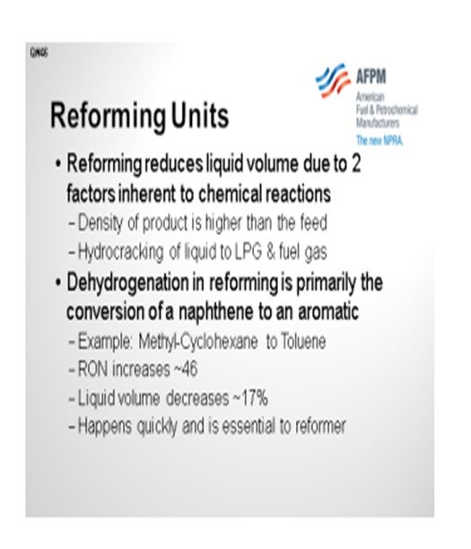
I will start with a bit of review of some reactions, and then I will get into a couple of examples of what we have done at HollyFrontier. Of course, the downside to reforming is that the liquid product has less volume than the feed to the unit due to physical laws inherent to the chemical reactions. First, the high-octane product will have a higher density than the feed; and second, some portion of the feed will be cracked to LPGs and fuel gas in the process.
There are three main classes of reactions in the reformer: dehydrogenation, dehydrocyclization, and isomerization. An example of dehydrogenation is the conversion of methylcyclohexane to toluene. The octane is increased by 46, but the downside is that the liquid volume decreases about 17%. This reaction happens very quickly in the reformer.
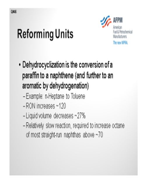
The second main reaction is dehydrocyclization, which is the process of a paraffin going to a naphthene and then ultimately to an aromatic. The example shows normal heptane (n-heptane) going to toluene, which has a large octane increase of 120. However, it also has a massive liquid volume decrease of 27%. A few refiners might be tempted to try to avoid this reaction; but unfortunately, it is necessary because you cannot really get the octane of a straight-run naphtha much above about 70 (R+M)/2 without this reaction.
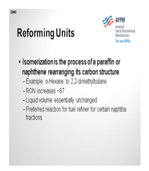
The third major reaction is isomerization, which is the process of changing the carbon structure of the molecule. The example shows normal hexane going to 2,2-dimethylbutane. The octane increase is about 67. The beauty of this reaction is that the liquid volume is essentially unchanged. So, in many respects, this is the preferred reaction. Of course, not all isomerizations have this big of an octane improvement.
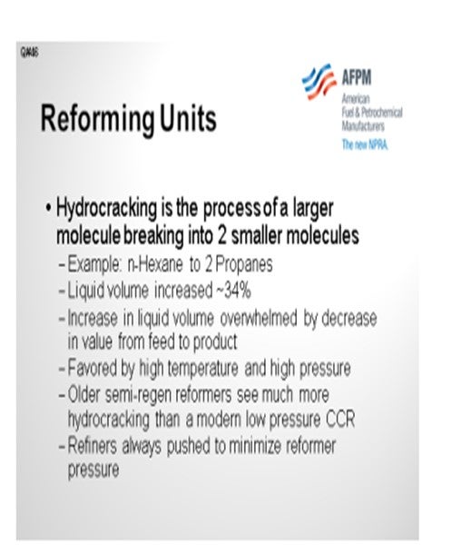
Finally, hydrocracking is generally undesired in a reformer. The example on the slide shows normal hexane going to two propane molecules. In this case, the liquid volume has increased significantly; however, the value of the propane is dramatically less than the value of the gasoline that it was when it started. Of course, that is even more so the case today with the high price of crude relative to natural gas.
So specifically, HollyFrontier has several older semi-regen reformers that operate at relatively high pressures to reduce the coking with the goal of achieving an acceptable run-length between regenerations. The reality of the current large differential between crude and natural gas has forced HF to look hard at the operation of these reformers. The price differential between crude and natural gas always drives us to minimize the severity of octane of these reformers, but
we also have to deal with our day-to-day constraints. The price differential would tend to push us to regenerate more quickly, but that is often not advantageous. The reason is that the outage time, due to the additional regeneration, is usually not enough to make up for the higher liquid yield.
As mentioned earlier, being able to produce E10 gasoline is, of course, of benefit for lowering severity. This is especially valuable for a high-pressure reformer. Some refiners separate aromatics for sale as chemicals. At one of the HollyFrontier sites, we deal with the particular process of extracting benzene. We have reviewed this quite a bit. For example, the conversion of normal hexane or methylcyclopentane to benzene results in a liquid volume
reduction of 32% or 21%, respectively. Initially, you see that that benzene has a much higher price than gasoline, but its higher price is almost wiped away when you consider the reduction in volume that you get for making it.
An alternative for some refiners might be to isomerize that C6 portion of the gasoline, instead of trying to make it into benzene, and then recover the benzene. We are evaluating this option at one of our sites. Of course, I want to mention that C5s should always be routed away from a reformer because they have no chance of making an aromatic. Unfortunately, they do have a good chance of cracking, especially in a high-pressure unit. C5s should generally be directed to an isomerization unit.
At one of our units, we have occasionally reduced the feed rate to a semi-regen reformer, which allows us to significantly increase the volume yield of the overall refinery. At our El Dorado plant, we have taken advantage of the lower feed rate by lowering the pressure on this particular reformer by about 75 psi. As a result, we see our liquid volume yield go up by approximately one percent. The unit does not have a net gas compressor. In order to lower the
pressure, the net gas must be compressed through the recycle compressor to “get into” the hydrogen header. Since the feed rates are reduced, the hydrogen-hydrocarbon ratio stays about the same for the lower recycle gas rate.
At another plant that also has a fairly high pressure semi-regen reactor, we have a unit with a compressor between the low-pressure separator and the high-pressure separator. This unit was designed to take the net gas off of the high-pressure separator. However, excess hydrotreater
makeup compression at downstream units now allows the net gas to be taken from the low-pressure separator. This yields a larger hydrogen-hydrocarbon ratio because the recycle compressor does not have to process that net gas, so the pressure in the unit is run a little bit lower. Of course, this depends on being able to have a compressor downstream that can handle lower pressure net gas. One downside is that the net gas purity is lower since it came from the
lower pressure separator.
The original question asked about chloride on the catalyst. HollyFrontier has not attempted to modify the chloride on catalyst, so I do not have any comment about that scenario.
MUEHLBAUER (Valero Energy Corporation – Benicia Refinery)
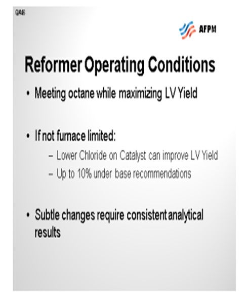
Similar to what Mark just said, we believe that operating the reformer is all about meeting the octane pool demand while maximizing the liquid volume yield. That has been the same strategy we have used regardless of natural gas prices changes. It has always been the most economic strategy. The exception is that if the refinery is hydrogen-limited, then you will have to factor the hydrogen economics into that decision as well. But more specifically to the chloride on
catalyst, we have actually found that the chloride drives the acid function on the catalyst in the ring-closing reactions.
Reducing the amount of chloride on catalyst can directionally improve liquid volume yield. In some cases, we have under-chlorided up to about 10% of the manufacturer’s base recommendations. We have done that in about a third of our reformers. On the other two-thirds, we actually operate about 5% lower than the recommendations. Some units operate the last reactor above the manufacturer-recommended chloride levels because we are heater-limited in those particular units. So, if you do not have the furnace, then the chloride will help you.
Even at the 10% level, these changes are very subtle: no more than up to 0.3 vol%. Therefore, it is directionally helpful. If you go too far, you could get catalyst agglomeration issues. We found that it is advisable to calibrate your local lab with either the licenser’s lab or some standard lab that you trust, just to be able to see some of these changes.
KOONTZ (HollyFrontier Corporation)
Naphtha reformers are critical units for U.S. refiners to increase the octane of straight-run naphtha for gasoline blending and to produce GT-BTX® for the chemical industry. However, the downside of reforming is that the product C5+ liquid volume is significantly lower than that of the feed. This results from two consequences inherent to the chemical reactions. The high-octane product is higher density than the feed, and some of the feed is cracked to LPG and fuel gas.
There are three main classes of reactions that increase the octane of the product: dehydrogenation, dehydrocyclization, and isomerization. Dehydrogenation is primarily the process of a naphthene producing an aromatic and hydrogen. As an example, methylcyclohexane could be converted to toluene and hydrogen. This process would increase the RON (research octane number) of the MCH (methylcyclohexane) by ~46, but it would also reduce its liquid volume by ~17%. This reaction happens quickly and is primarily catalyzed by the metal function of the catalyst.
Dehydrocylization is the process during which a paraffin produces a naphthene and hydrogen. The naphthene will generally proceed to an aromatic via dehydrogenation. As an example, n-heptane could be converted to toluene and hydrogen. This process would increase the RON of the nC7 (normal heptane) by ~120, but it would also reduce its liquid volume by ~27%. This reaction is the slowest of the primary reactions in a reformer. The ring-forming is primarily
catalyzed by the acid function of the catalyst and the dehydrogenation is due to the metal function. It results in a large reduction of liquid volume; but without it, the octane of a typical full-range naphtha can get no higher than 60 to 70.
Isomerization is the process of a paraffin or a naphthene rearranging its carbon structure; for example, n-hexane (normal hexane; nC6) could be converted to 2,2-dimethylbutane. This process would increase the RON of nC6 by ~67 with essentially no change in liquid volume. The reaction rate falls somewhere between dehydrogenation and dehydrocyclization and is primarily catalyzed by the acid function of the catalyst. For a fuel refiner this is generally the ideal
reaction; however, most other isomerizations do not result in such a large RON improvement.
Hydrocracking is the fourth main class of reactions in a reformer and is generally undesired. As an example, n-hexane plus hydrogen could be converted to two propane molecules. The reaction is favored by high temperature and high pressure and is primarily catalyzed by the acid function of the catalyst. This process would increase the liquid volume by ~34%, but the value of propane is tied more closely to that of natural gas than to crude oil. With
the price of crude near historical highs and the price of natural gas near historical lows, the volume increase is nowhere near enough to make up for the decrease in value.
Older semi-regeneration reformers were designed for higher pressures to reduce coking and enable the unit to run for an acceptable time between outages to regenerate. The impact of the large differential between crude and natural gas more greatly affects a reformer operating at
higher reactor pressures due to increased hydrocracking. This would generally drive the daily optimization to minimize reformer octane (i.e., severity or temperature). It would also push a refiner to regenerate catalyst in semi-regeneration reformers more often to avoid the EOR (end-of-run) conditions when reformer temperatures and hydrocracking are higher. However, the increased yield from the regeneration must be balanced with the lost opportunity due to the outage.
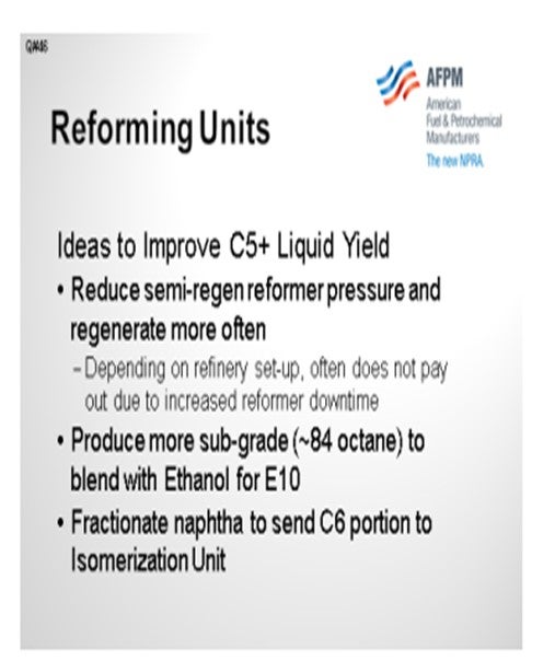
Producing sub-grade gasoline for blending with 10% ethanol can be a significant benefit for a refiner having a reformer with low liquid product yield. The lower octane of the sub-grade (~3 points lower) allows the refiner to run the reformer at lower severity or bypass sweet naphtha around the reformer directly to gasoline.
Some refiners separate aromatics from the reformate for sale to the chemical industry. One particular aromatic that HF (Editor’s note: HF stands for HollyFrontier in this response) has evaluated is benzene. The conversion of n-hexane or methylcyclopentane to benzene results in a liquid volume reduction of 32% or 21% respectively. The increased price of benzene over gasoline primarily reflects this reality. An alternative for a refiner would be to send the C6
portion of the naphtha to an isomerization unit to avoid the volume loss inherent to a reformer.
C5s should always be routed away from a reformer and generally to an isomerization unit. C5s will not form an aromatic, but they could hydrocrack to LPG and fuel gas in a reformer (especially in a high-pressure unit).
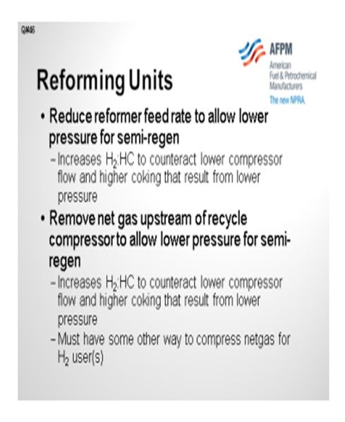
Reformer yield can be improved by lowering the feed rate, especially for a semi-regenerator. Reducing the feed rate can be accomplished by fractionation to route light naphtha to isomerization and heavy naphtha to distillate, or via the crude slate to reduce the total straight-run naphtha. The HF ElD (Holly Frontier, El Dorado, KS) reformer takes advantage of this at times and lowers the reactor pressure by as much as 75 psi. This increases the product C5+ liquid
yield by as much as 1 LV%. The unit does not have a net gas compressor due to the high separator pressure. At low rates the pressure is reduced and the recycle compressor also compresses the net gas (lowers recycle rate). However, due to the lower feed rate, the H2: HC
ratio and coking rate both remain about the same.
HF Cheyenne has reduced its semi-regeneration reactor pressure in a different way. The unit has a low pressure and a high-pressure separator with a compressor in between. The unit was designed to take the net gas off of the HPS (high pressure separator). However, excess hydrotreater makeup compression allows net gas to be taken from the LPS (low pressure separator) and yields a larger H2: HC ratio. The reactor pressure can now be run lower (higher liquid yield) and achieve the same coking rate due to the higher H2: HC. One downside is that the net gas is lower purity having originated from the LPS.
HF has not attempted to modify the chloride on catalyst in its reformers to alter the acid function of the catalyst. It is recommended that you consult your catalyst supplier before attempting a change such as this.
SUBHASH SINGHAL (Kuwait National Petroleum Company)
Chloride on catalyst is maintained at a desired level (1 wt% to 1.2 wt %) for optimized catalyst performance and to ensure that balance of metal and acid activity. At KNPC, we never alter chloride on catalyst to shift yields to gas/LPG.
Year
2012
Process
Question 47: How often do you replace your reformer catalyst? What is monitored, and what triggers the replacement? How has the increased spread between natural gas prices and liquid product prices impacted these decisions?
KOONTZ (HollyFrontier)
HollyFrontier operates five semi-regen reformers and two CCRs. There has not been a specific effort to replace catalyst in order to take advantage of the higher liquid product yield that is possible with newer catalyst. However, the spread between natural gas and liquids certainly impacts the decision when looking to upgrade. For two of the semi-regen units, the most recent catalyst replacements were installed after approximately 20 regen cycles, which included multiple dumping and screening events. HollyFrontier would generally only consider replacement during a turnaround, which is about every five years, because it would not be worth shutting down the unit.
Tracking liquid product yield as a function of octane over time is the most important factor used to justify new catalyst. Of course, today, with the large spread between gasoline and fuel gas, that breakeven point would probably be sooner, especially on high pressure units. Replacing relatively new catalyst with more advanced ones is also considered; however, we would be cautious about doing that because of the difficulty of comparing pilot plant data with operating data from our plants.
DUBIN (Axens North America)
We consider typical replacement levels to be six to eight years for moving-bed, eight to 10 years for fixed-bed, and three to seven years for cyclic units. Those ranges are based on typical regeneration frequencies and good quality regeneration, as well as proper hydrotreatment of the feed to the reformer. We know that surface area is lost with each regeneration; so, whatever your regeneration, you are going to lose yields relative to your initial yields. But as Mark
mentioned, replacement on lost yields relative to initial yields should not really be the only basis.
The most current catalysts on the market may offer improved economics. Due to a changing feed composition or product severity required, a newer generation catalyst may offer an economic incentive over your current load. A detailed evaluation should be conducted to determine the economic drivers at your particular site, in terms of hydrogen, its need, and its value. The same is true for the liquid products. This will help you determine if it makes economic sense to send the existing load to reclamation and purchase a new load of catalyst.
On the valuation of natural gas, we have seen that the reformer hydrogen is generally being devalued. Natural gas prices are so low that new steam methane reforming units are being brought on stream both for ULS (ultra-low sulfur) fuels production, as well as general upgrading. The hydrogen from hydrogen plants is preferred in both quantity and quality. In terms of total quantity available, you can build your hydrogen plant for whatever your need is going forward. The quality of the hydrogen from the hydrogen plants is near pure leading to improved partial pressures and potentially reduced equipment sizes.
RON MARRELLI (HollyFrontier)
Both of you mentioned a specific time between regenerations. Is time the main factor in determining frequency of regeneration or catalyst surface area? What is the best way to really determine when the catalyst needs to be changed?
DUBIN (Axens North America)
For a moving-bed, Axens recommends tracking surface area. In general, you should see that surface area will trend with yields. Tracking surface area can be done quite easily for moving-bed applications. For fixed-beds, it is not as easy on a continuous basis; but during any regeneration or dump-and-screen, you can track and note the surface area. Ultimately, it will be the yields that justify changing out the catalyst.
KOONTZ (HollyFrontier)
I agree with his statement.
MUEHLBAUER (Valero Energy Corporation – Benicia Refinery)
UOP’s experience with units of similar age to ours has indicated that the key to maintaining long catalyst life and good performance is ensuring good platinum dispersion. If we can maintain good platinum dispersion, then product yields from the CCR Platformer unit, reformate production, and hydrogen production will remain flat over time. In some of the pressurized regenerators, CycleMax regenerators, and even atmospheric units, we have had up to a thousand regeneration cycles with no real loss and C5 plus yield or total aromatics yield. It is not as simple. Like the question before, there is not really one simple answer as there was with iron. If you want to talk more about it, feel free to stop by at the UOP suite. We can have a discussion.
KOONTZ (HollyFrontier Corporation)
HollyFrontier operates five semi-regeneration reformers and two CCRs. There has not yet been a specific effort to replace catalyst to take advantage of higher liquid product yield; however, this certainly impacts the decision process when looking to upgrade to a better catalyst. For two of the semi-regeneration units, the most recent catalyst replacements were after approximately 20 regeneration cycles (also included multiple dump and screen events). HF would generally only consider a catalyst replacement during a turnaround (about every five years). Tracking liquid product yield as a function of octane over time is the most important factor used to justify new catalyst. With today’s large price spread between gasoline and fuel gas, the break-even point to replace catalyst is certainly sooner than in the past. Replacing relatively new catalyst with a more advanced catalyst is also considered. However, care must be taken to assure that a yield improvement prediction for a new catalyst is not due to different feed properties or operating conditions.
DUBIN (Axens North America)
Typical replacement levels are six to eight years for moving-bed applications, eight to 10 years for semi-regeneration units, and three to seven years for cyclic. The ranges are based on typical regeneration frequencies, good quality regenerations, as well as proper hydrotreatment of the reformer feed. A reduced catalyst life could be expected with increasing regeneration frequency as surface area is lost on the catalyst with each regeneration leading to a reduction in
reformate yield relative to the initial yield.
Changing the reformer catalyst solely because the yields have decreased relative to the start of the run should not be the only basis for replacement. Replacing the existing catalyst due to advances in reforming catalyst technology, changes in unit severity, or changes in the unit feed composition, may still make economic sense even if the current catalyst load still has life left. A new load of catalyst could bring improvements in any number of economic drivers,
reformate yield, hydrogen yield, increased cycle length, etc. If the combined improvements in the economics of the reformer provide a desirable rate of return, then it makes sense to send the existing load to reclamation. Axens has developed a tool with just this idea in mind. Looking at the key economic drivers in the reformer to help refiners understand whether a newer catalyst load will offer a greater profit than what their current operation is providing.
However, it must be noted that the very low prices of natural gas are leading to a de-valuing of the reformer hydrogen production. New steam methane reformers (SMR) are being built at a number of sites to help meet both ULS fuel production, as well as upgraders. The increased hydrogen production by SMR devalues the reformer hydrogen not just because of the increased quantity often available, but also because of the increased quality. The high purity
hydrogen available by SMR can significantly improve hydrogen partial pressure for high pressure units, reducing costs, and further decreasing the value of reformer hydrogen production.
Year
2012
Process
Question 48: Discuss recent advances in reforming catalyst technology. What performance improvements are being researched?
DUBIN (Axens North America)
The most current catalysts on the market are multi-promoted using a number of different promoters beyond the base platinum-rhenium or platinum-tin. It is not a one-size-fits-all market, so there are tailored designs for different needs. For CCRs, the current drive is for improved yields. Units are often octane-long. The goal is now to maximize barrels as best as we can. We can then try to contrast to the early 2000s where gasoline was high in demand and high activity.
Moving-bed catalysts were desired to keep coke make down or within the design parameters of the existing unit. For fixed-bed units, we are now seeing the drive towards increased stability. Refiners are trying to push the time between regenerations as long as possible. The economic incentive to stay onstream is bigger than the extra octane barrels or liquid volume product derived from a different type of catalyst.
JOE ZMICH (UOP, A Honeywell Company)
UOP is always looking to improve the catalyst performance; not only activity, meaning lower reactor inlet temperatures for desired octane, but also higher reformate production. In the North American market, it becomes a little more complicated with reformers intending to operate at much lower octane. As octane is decreased, the paraffin conversion in the reactor system will go down. You will then be relying on differentiation of naphthene, specifically C5-ring naphthene conversion. It is more difficult to differentiate catalysts at low paraffin conversion.
DUBIN (Axens North America)
The newest generation of reforming catalysts is multi-promoted using a number of different metals beyond the base platinum and rhenium or tin. These promoters are being used to tailor the operation to fit exactly what the refiner needs, as opposed to a one size fits all market.
The current market drive for continuously regenerated catalyst is for increased yields. As the overall gasoline market stagnates, refiners have been looking to recover as many barrels as
possible from their units while operating at reduced severity. Many refiners are octane long, reducing the need for high activity catalysts. This is a big change from the early 2000s when refiners were looking to maximize gasoline octane out of their continuously regenerated reformers, requiring high activity catalyst to keep coke within the design range on their unit.
For the semi-regeneration market, the driver has been towards increased stability.
Refiners are trying to maximize their time on stream, using the reduced coke make in the current generation of semi-regenerative catalysts to stretch the time between regenerations. The savings, obtained by staying on stream, are often a bigger driver than extra octane barrels or hydrogen.
SUBHASH SINGHAL (Kuwait National Petroleum Company)
There are continuous advancements in catalyst systems for increased cycle length and product selectivity. Performance improvement – in terms of high octane, high H2 rich gas, high LPG, and less fuel gas – are important to researchers.
Year
2012
Process
Question 49: Does the panel have any experience using flexible thermocouples in the regeneration section of a moving-bed reforming unit? What considerations should be given to revamping units that do not have these installed?
STEVES (Norton Engineering Consultants, Inc.)
Flexible thermocouples, as I understand, are now a part of the standard design for regenerators of moving-bed units. At a refinery in which I worked; we replaced the original slider thermocouples with multipoint thermocouples. In this particular case, there were three sets of thermocouples installed on the outside of the regeneration screen in order to obtain temperature readings in the bed. Each thermowell contained eight thermocouples spaced at one- foot intervals down a length of the screen. When specifying these types of thermocouples, it is important to determine if a representative cross-section of temperatures is being collected for the bed.] You can easily obtain many temperature readings. As mentioned in my answer to Question 31, proper temperature monitoring can be critical to ensure that the burn is progressing properly and that there are no temperature excursions. In my mind, it is better to have too many temperatures than not enough and potentially be running blind.

DUBIN (Axens North America)
What Chris said is true for Axens. The standard design would include flexible thermocouples. They do offer the ideal ability to locate the temperature measurement points exactly where you desire them. Also, the number of points can be significantly increased with a minimum number of nozzle projections off the side of your regenerator.
PATRICK BULLEN (UOP, A Honeywell Company)
Our standard offering for the CycleMax is to use the flexible thermocouples. Most units are either Gayesco or Daily Thermetrics. Daily Thermetrics is very popular right now. The main issue is replacement in old atmospheric units. It is difficult to use the Gayesco or Daily Thermetrics systems due to space considerations and the logistics of getting the thermocouples into the regenerator area.
R.K. (RICK) GRUBB (Chevron Products Company)
Do you have much experience with thermocouples in a fixed-bed reformer?
DUBIN (Axens North America)
At Axens, we have completed revamps of fixed-bed reactors with the addition of thermocouples. On older units, avoiding welding on the shell is often desired. Ideally, it is preferable for you to make use of an existing nozzle.
Process
Question 50: How do you monitor the integrity of internals, and how do you determine when to replace reforming unit reactor center screens? What is the typical life of the center screens, and when are repairs considered excessive?
DUBIN (Axens North America)
Typically, we have seen internals last between 15 and 20 years, if not longer. At any point, it becomes a value judgment between the number of repairs you have made, if any, and the potential outcome if the internals do fail. You can consider patching and patching and patching until major damage occurs, or you can take a more proactive approach and say, “We anticipate something happening in the not-too-distant future, so how critical is it for the reformer to stay up within the refinery?” We recommend replacing the internals at the first major turnaround after the 15-year mark as an ideal time. Ultimately, it is a site-dependent issue based on the quality of the inspection program, how often you have investigated the condition of your internals, what repairs you have had to make, and whether you have had any unusual events on your unit. Additional thermal cycling of the reactors (or in the case of a moving-bed unit, the regenerator) beyond the standard operating ranges should be included in the need for internals replacement.
KOONTZ (HollyFrontier)
HollyFrontier does not really have a set proactive plan to replace center screens at a normal interval. Of course, they are inspected during the outages. Typically, the screens have been repaired as needed. We have not experienced any significant problems with our CCRs in our recent history. The two CCRs we have been fairly new, less than 10 years old, so they have not had any major repairs yet.
JOE ZMICH (UOP, A Honeywell Company)
In general, from a CCR Platforming unit licensor perspective, we see that the industry is shooting for around a five-year turnaround cycle. Each five years, you should consider a shutdown so you can do a thorough inspection of the reactor center pipes and on the regenerator side as well. On the center pipes in a CCR Platforming unit, there is no standard time frame. People have gone as long as 10, 20, or 25 years with little to no damage on center pipes, while others have gone 10 years and had significant damage. Some of these issues have to do with the geometry and design of the reactors rather than the thermocycling history of the reactor and whether there has been emergency shutdown. These are the factors to consider regarding the need to change out the internals of the reactor section.
DUBIN (Axens North America)
Axens recommends replacing the reformer internals at the first reasonable opportunity after the internals have been in services for 15 years. This does not mean the refiner should bring the unit down at the 15-year mark to replace internals; rather, plan on replacing the internals at the next major turnaround after the 15 years of service for the internals.
Due the thermal stresses seen by reactors, and regenerator for the continuously regenerated designs, the V wire eventually will become more and more brittle, allowing for a potential failure. Any site-specific issues such as bringing the unit down often for other reasons,
loss of power, etc., causing the V wire to cool down and heat back up will only further stress the materials.
The drive to replace the internals becomes an overall economic comparison between the chances that the internals fail, the failure severity, and the impact on the rest of the refinery if the reformer must be shut down for an internal-related problem. A major key to preventing unplanned shutdowns, and one that the licensor often cannot help with, is each refiner’s inspection program. A thorough review of the internals at each opportunity will give the best overall picture for the quality and viability of each site-specific set of internals.
KOONTZ (HollyFrontier Corporation)
HollyFrontier operates five semi-regeneration reformers and two CCRs. The screens are carefully inspected during turnaround (about every five years). Historically the center pipe screens have required only minor repairs and are not on a regular interval for replacement. If significant damage was found during an inspection a decision would be made as to whether it makes more sense to repair or replace. The current screens have been in service for decades and
there are no plans to replace them. The CCRs are fairly new (less than 10 years) and have not required center screen replacement.
Year
2012
Process
Question 51: What is the panel’s experience with recycle gas moisture analyzers?
PIZZINI (Phillips 66)
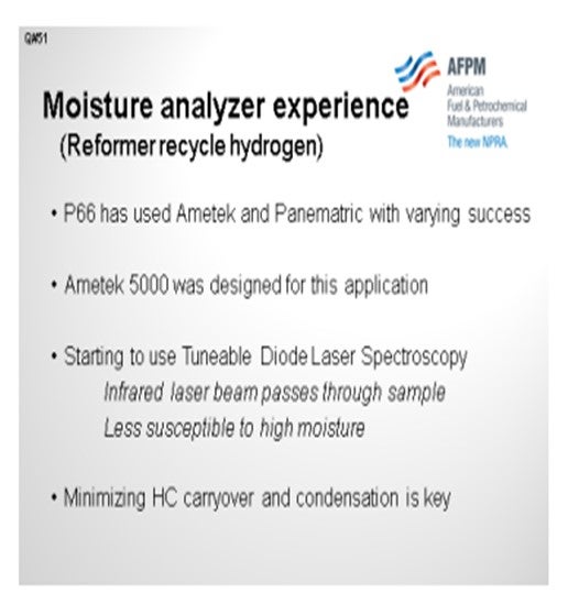
Phillips 66 has had experience with the Ametek and Panametrics moisture analyzers. Weare talking about moisture in the reformer recycle hydrogen, so we are looking for 10 ppm to 50 ppm with varying success. I do not think we could say that one is a lot better than the other. The Ametek 5000 was designed for that application. More recently, we have been looking at a different technology: tunable diode laser (TDL) spectroscopy. It is an infrared beam that passes through the sample, so it is less susceptible to high moisture. We are getting some experience with that technology. Regardless of any of these types of analyzers, it is important to minimize hydrocarbon carryover into the sample system.
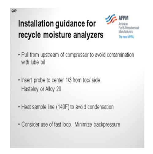
The next slide contains a few Best Practices for recycle moisture installation. You want to make sure you pull upstream to the compressor to avoid getting lube oil contamination in the sample. Our advice is to use a probe and insert it roughly one-third of the way into the pipe, either from the top or the side but not from the bottom. Use a high alloy, such as Hastelloy or Alloy 20, so the probe will still there in 10 years. We recommend heating the sample line to prevent condensation of droplets of hydrocarbon, primarily in the sample system. If the analyzer is some distance away from the samples, we recommend a fast loop to a location with minimal back pressure, typically to a flare.
PATRICK BULLEN (UOP, A Honeywell Company)
In the application using GE-Panametrics for isomerization units where the normal reading is near zero, it can be difficult to calibrate or check the sample. Therefore, we need to have the analyzer online continuously. UOP have developed a recommended preventative practice to send the probes back to the manufacturer for recalibration every six months.
PIZZINI (Phillips 66)
Historically, Panametrics and Ametek moisture analyzers have been used with varying success depending on the nature of the recycle stream. The Ametek 5000 was specifically design for this application and has an integral moisture generator used to check calibration. If there is only a little HC liquid carryover in the recycle, and if the sample systems are set up correctly, then the Panametrics and Ametek analyzers work well. We are starting to use tunable diode laser-type analyzers that are on the market and have found them to work well if there is little HC carryover and condensation in the sample lines. The TDL analyzer is less susceptible to high moisture as compared to the electro-chemical cell analyzers.
Maintaining accurate, online moisture measurement is difficult and requires a commitment for routine calibration and maintenance. The precise, absolute value is prone to inaccuracy; however, there is value in the general moisture trend, especially when used in combination with unit yield monitoring.
Year
2012
Process
Question 52: What is your recommended method for mitigating fouling in reforming unit recycle compressors? Has any technique proven successful? Is anyone using reformate to clean the compressor online?
MUEHLBAUER (Valero Energy Corporation – Benicia Refinery)
The best method for reducing fouling in the compressor is to take the nitrogen out of the feed. In Valero, we have recently reviewed our naphtha hydrotreater performance. In a lot of cases, we found that the naphtha hydrotreaters can actually be pressure drop-limited versus activity-limited. We have changed some of the operating philosophy on some of the units to the point of operating them at higher temperatures knowing that if the unit was pressure drop-limited, then we might be leaving activity on the shelf. So, operating the reactors at a higher severity is one of the moves that could be possible to remove nitrogen from the reformer feed.
Also, using a catalyst like a NiMo (nickel molybdenum) can promote the HDN (hydrodenitrification) reaction in the upstream hydrotreater. I think those two steps are probably the best ways we have found to mitigate the compressor fouling. In the event that the compressor does get fouled during online water-washing, which we have experienced at two of our locations, we will work very closely with the Rotating Equipment Group and the compressor manufacturers which both have very specific procedures on how to perform the waterwash. We have been successful mitigating the effects of cleaning the fouling with online water-washing. We are actually water-washing one unit, at one point, on a daily basis. With that frequent exposure, one of the side effects we saw was that we had less chloride retention on some of our catalysts, just with the added moisture to the system.
Finally, if the goal is to just extend the interval between times for the shutdown and offline water-washing of the compressor, we have been successful revalidating the trip setting on the hydrogen flow. In some events, we found that the initial trip setting we used was not necessarily based on the process limitation; it was more of an instrumentation limitation and dependent on how accurate the instrument would read at the lower flow rates. So, by changing the flow instrument technology, we were able to get more accuracy and perhaps lower that trip setting to get a couple more months between shutdowns. If you end up doing that, you will have to closely examine the economics around the compressor inefficiency. However, you may gain the extra couple of months you need to do a scheduled shutdown.
PIZZINI (Phillips 66)
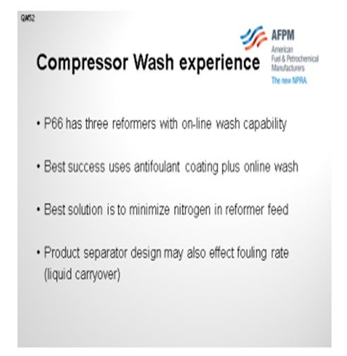
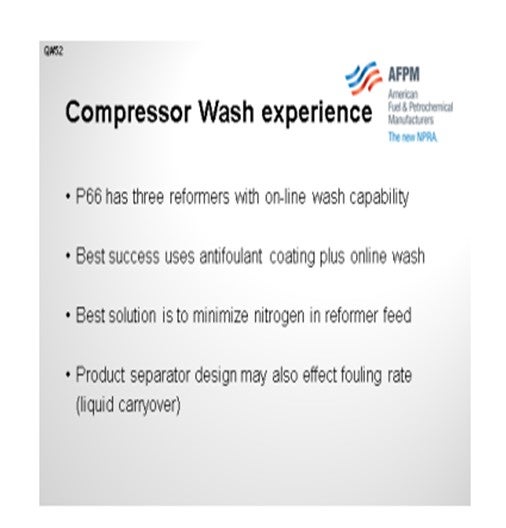
The Phillips 66 experience with online washes: We have three reformers set up for an online wash, although I believe only one uses it continuously. These are all naphtha washes, by the way. We have had the best success at a site that combines the naphtha wash with a coding on the compressor impeller; so, it is using both techniques. To echo what Joe said, keeping nitrogen out of feed is your best option. We have some evidence that the design of the product separator makes a difference, for example, the distance between the liquid level and the outlet nozzle.
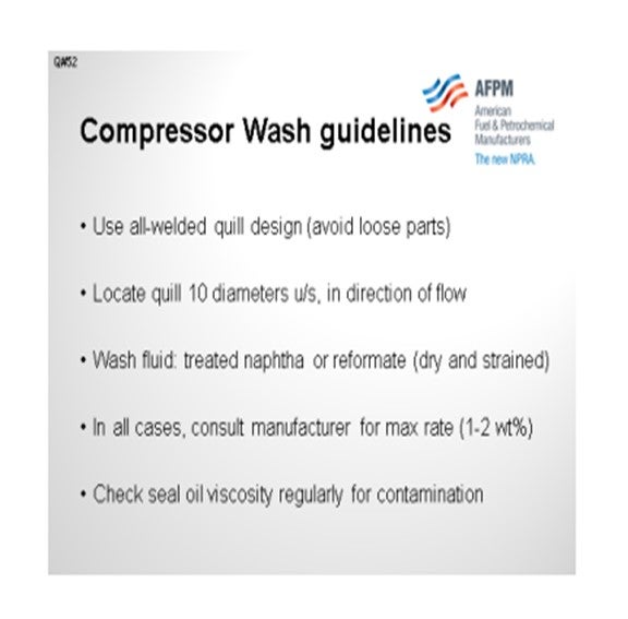
On the next slide, I have listed some Best Practices as guidelines for installing these wash systems. We recommend an all-welded design. You do not want any loose parts in front of a compressor. Locate the quill 10 diameters upstream of the compressor and aim the quill in the direction of the flow. For our wash fluids, we recommend using dry naphtha range hydrocarbon and routing it through a strainer to take out any particles that might be present. The next bullet should probably have been first. Any time you undertake this kind of wash, make sure the manufacturer has reviewed your plans and agrees with the amount of liquid you are planning to inject. In some of our refineries, the target is 1 wt% or 2 wt% of liquid relative to the vapor flow through the machine. Lastly, check the seal oil viscosity to make sure there is no naphtha leakage into the seal oil.
WILLIAM BANDY (Tesoro Refining and Marketing Company)
My question is about the waterwash on the recycle compressor. Are you talking about centrifugal compressors, and do those have dry gas seals or not?
MUEHLBAUER (Valero Energy Corporation – Benicia Refinery)
I am actually not sure about the type of seal design on those compressors. Our Reliability group and equipment manufacturers did note that having the ability to control the speed of the compressor was one of the main factors used when choosing the suitability of waterwash for particular compressors. Turbine-driven is preferred to be able to drop it down to a minimum speed before performing this procedure, but I am not sure about the seal design.
WILLIAM BANDY (Tesoro Refining and Marketing Company)
I think you have to be really careful with gas seals. We used to water-wash the centrifugal compressor on our reformer all the time to get rid of salt fouling. And then during the last turnaround, we converted to dry gas seals. According to the seal manufacturer, we are no longer able to water-wash, so we are in a bind.
The other question is for Paul. When you mentioned a naphtha wash, did you mean a continuous naphtha injection into the suction of the compressor? You did not mean filling the case with naphtha, did you?
PIZZINI (Phillips 66)
That is right: a continuous wash into the suction of the compressor. Also, if a compressor has already gotten really dirty, you have to think twice about establishing that wash. It might throw off the wheel balance. So, when we do the online wash, we would like to start with a clean impeller and continue it throughout the run.
WILLIAM BANDY (Tesoro Refining and Marketing Company)
We do that, too. I just was not sure if you meant a continuous naphtha injection or some kind of a discontinuous batch wash. Thanks.
ALLEN KAISER (Delek Refining Ltd.)
When we have the liquid wash, does the compressor face any vibration issues? In the case of a waterwash on a continuous basis, is there an issue with the moisture control in the recycle gas?
PIZZINI (Phillips 66)
In response to the vibration question, the vibration is really the reason they are doing the wash in the first place. It is generally not done on a compressor that goes three years without a vibration problem. We have only installed wash systems where there were known vibration issues.
MUEHLBAUER (Valero Energy Corporation – Benicia Refinery)
I will add just a few comments. We monitor the vibration throughout the procedure. Monitoring the compressor vibration during the procedure and noting the decrease in vibration levels will indicate that the compressor has cleared up. With regard to the recycle gas moisture: These online waterwashes are done for a matter of seconds or minutes. So, we do not go out of the way to monitor the recycle moisture. We believe that some of the older grades of catalyst had a harder time retaining chlorides with frequent washing.
BRAD PALMER (Phillips 66)
Joe, about how much water is being injected during those online washes? You said for just a few seconds to minutes, but how much are you adding?
MUEHLBAUER (Valero Energy Corporation – Benicia Refinery)
It is not much. The number I was quoted was about one gallon per minute, which might actually correspond to this 1 wt% range.
R.K. (RICK) GRUBB (Chevron Products Company)
You said seconds or minutes. How do they actually determine how long?
MUEHLBAUER (Valero Energy Corporation – Benicia Refinery)
We monitor the compressor vibration, which apparently comes down right away.
PIZZINI (Phillips 66)
At P66, our experience has been mixed as to the effectiveness of online compressor washes. We have three units that have the capability for online naphtha washing, but only one is currently using it. We have also tried coating the rotors. Our best success was where we have both an anti-foulant coating plus an online naphtha wash. This area is so subjective because every unit is different and the amount of nitrogen in the feed and other water/chloride conditions
effects where ammonium chloride lays down and how rapidly. The design of the upstream separator can also affect the fouling rate of the compressor. By far, the best solution is preventing nitrogen from reaching the reformer.
In all cases the compressor manufacture should be consulted in developing any offline waterwash procedures, online naphtha wash systems or coating applications. Whenever a compressor is water-washed the reactor effluent exchangers, trim coolers and stabilizer overhead should also be evaluated for waterwashing.
Use an all-welded quill design because you do not want pieces coming off. The quill should be located 10 diameters upstream of compressor, oriented with the flow. The maximum rate, as approved by the manufacturer, is 1 wt% to 2 wt%. Use low moisture low solids naphtha or reformate, routed through a screen. Use buffer gas to prevent contamination of the seal oil. Typical buffer gas is hydrogen set at 4 psig to 7 psig above the seal chamber suction pressure. Check the viscosity of lube and seal oil to ensure oil not being contaminated by the wash fluid. Monitor compressor performance and vibration on a regular basis.
BRUCE WRIGHT (Baker Hughes)
The foulant material is typical salts, iron sulfide, or corrosion products. Baker Hughes ’antifoulant additives have been successfully used to mitigate compressor fouling. However, proper additive injection techniques are required to ensure program performance and avoid potential problems.
Year
2012
Process