
Question 4: The economic benefit for propylene and amylene alkylation is improving. What considerations do you use in the feed pretreatment and alkylation unit operations before increasing these feeds?
CHRIS STEVES (Norton Engineering)
Increased processing of propylene and amylene feedstocks in alkylation (alky) units does bring challenges, but most will depend on the configuration of the existing unit and whether any of these feedstocks have been processed before.
Modification of a butylene-only alkylation unit to handle larger volumes of propylene may involve significant capital modifications to add or expand the capacity of C3 handling equipment. Examples include the depropanizer, C3 defluorinations (in HFalky units), and refrigeration equipment (for sulfuric acid alky units). With sulfuric acid alky plants, consideration will also be required for treating the reactor hydrocarbon stream before fractionation. Caustic treating systems may require the caustic circulation rate to increase by as much as twice the butylene-only rate to treat and remove esters from the reactor effluent of a propylene alky unit. In addition, the temperature required to break down these esters in the caustic treater will need to increase, potentially as much as 40°F above current operating temperatures, due to the higher stability of esters in the reactor effluent of a propylene alky unit.
In sulfuric acid alkylation units, separate reactors for propylene-rich and butylene-rich streams can help in managing acid consumption, as the different feedstocks respond differently with regard to acid consumption at different acid strengths and operating temperatures. A strategy of processing a propylene-rich stream in the high strength reactor and the butylene-rich stream in the low acid strength contactor can help to minimize overall unit acid consumption.
In addition to alkylation unit modifications for propylene alkylation, the alky feed treating will need to be reviewed to ensure that the sulfur is adequately handled and that C2is properly stripped from the alky feed stream. For addition of propylene feed, removal of H2S (hydrogen sulfide) with amine and/or expansion of the caustic pre-wash equipment should be considered so as to not negatively impact the operation of the mercaptan removal system with the production of non-regenerable sodium sulfide.
Addition of amylene to alky feed may also typically require modifications to the alky unit equipment. The extent of the modifications will depend on the desired level of amylene. Some considerations include the following:
In sulfuric acid alkylation units, amylene alkylation can be safely practiced at lower acid strengths than with propylene or butylene alkylation. With a separate reactor for amylene processing, the overall acid consumption on the unit can be minimized by allowing the final spending strength to fall lower than what would be practiced with butylene alkylation.
In sulfuric acid units, amylene alkylation is more sensitive to temperature than butylene alkylation; but with limited propane in a separate amylene reactor, the desired lower temperature may be difficult to achieve. Modifications to the refrigeration system may be required to optimize the individual reactor sections with regard to operating temperature.
In both sulfuric acid and HF alkylation, introduction of amylene feeds will increase production of isopentane through hydrogen transfer reactions (although at higher rates in HF alkylation). Removal of isopentane from alkylate may require fractionation changes in the alky unit. The isopentane production can be minimized through recycling of isopentane from the fractionation section back into the reaction zone, but this process would require additional fractionation equipment.
Amylene alkylation will also require a review of the alky feed treating system. Introduction of heavier feedstocks to the mercaptan treating section may impact the overall sulfur of the alky feed (which will then impact acid consumption), as the heavier mercaptans are more difficult to extract. Introduction of heavier feedstocks to the alky feed can also bring undesirable species into the alky feed, such as cyclopentane and diolefins which consume acid at a significant rate. While cyclopentane can usually be excluded from the alky feed via upstream fractionation, treatment of diolefins may require separate reaction systems to remove them from alky unit feed.
KURT DETRICK (Honeywell UOP)
The issues in an HFAlkylation unit are different for propylene and amylenes.
For Propylene:
The types of contaminants and the concentrations of those contaminants that must be removed in the feed pretreatment section is not much different from butylene. The one difference is that there can be some ethane and ethylene that comes in with the propylene feed. Ethane tends to act as a Non condensable and requires venting from the depolarizer overhead system, which will cause increased acid losses. Ethylene does not react with iC4 in the HF alky unit but tends to make ethyl fluoride, which will cause higher organic fluoride content in the untreated propane and resulting in higher alumina consumption in the propane defluorinations.
The operational issues with propylene are primarily increased consumption of isobutane and propane rejection. The increased isobutane consumption is due to the fact that about 20% of the propylene will undergo a hydrogen transfer reaction where one molecule of propylene will react with two molecules of isobutane to produce one molecule of propane and one molecule of isooctane (C8 alkylate). This reaction actually helps improve the alkylate octane, but it causes a somewhat higher consumption of isobutane than might otherwise be expected.
The propane rejection issue is often the controlling factor in how much propylene feed can be handled in each particular unit. There is a limit to how much propane the fractionation and stripping columns can handle, and that limit is dependent on the specific unit design. One problem that can occur as the amount of propane coming though the unit increases is that the concentration of propane in the main fractionator or isostripper overhead vapor increases, causing a decrease in the condensation temperature, and this temperature reduction can “pinch out” the overhead condenser, thus limiting the available cooling duty of this exchanger.
For Amylenes:
The types of contaminants present in the amylenes are a little different from the propylene and butylene feed. Also, the concentration of contaminants such as sulfur and diolefins is higher. These changes can require adjustment of the operation–or even the design –of the feed pretreatment units. For example, the heavier mercaptans that co-boil with amylenes have a lower solubility in caustic, and they tend to be present in higher concentrations; therefore, a higher caustic circulation rate may be required for the mercaptan extraction unit in the feed pretreatment section.
Amylenes can also undergo a hydrogen transfer reaction in which one molecule of amylene will react with two molecules of isobutane to produce one molecule of isopentane and one molecule of isooctane (C8 alkylate). As with the propylene hydrogen transfer reaction, the amylene hydrogen transfer reaction actually helps improve the alkylate octane; however, it causes a somewhat higher consumption of isobutane. The amount of amylene that undergoes this hydrogen transfer reaction depends on several factors and can be anywhere between 30% and 60%.
The isopentane that results from feeding amylenes (both in the amylene feed itself and that which is produced by the hydrogen transfer reaction) can cause the alkylate to have a somewhat higher Reid Vapor Pressure (RVP). It may be necessary to draw some of the isopentane out with the n-butane product if a relatively low RVP alkylate product is desired.
For Both Propylene and Amylenes:
The octane number –both RON and MON (motor octane number)–of the C7 and C9 alkylate that is produced is about 5 to 10 numbers lower than the RON and MON of C8 alkylate. So, higher concentrations of propylene or amylene in the feed will decrease the alkylate octane if all other variables are held constant. Of course, if the addition of propylene or amylene to the feed results in more total olefin in the feed to the unit, the isobutane-to-olefin ratio may decrease, which will cause lower alkylate octane and higher ASO production.
Year
2016
Process
Question 5: What are the typical dispositions of coker olefins, light coker naphtha, and heavy coker naphtha in refineries that you employ? How are the sulfur contaminants, such as dimethyl sulfide and dimethyl disulfide, best removed from these streams?
HUTCHINSON (Axens North America)
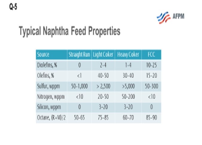
This question asks about the fate of coker olefins and coker naphthas. What we are looking at here are the three coker product streams, which include coker LPGs (liquefied petroleum gas), your C3s(propane/propylenes) and C4s (butane and butylenes), and light and heavy coker naphthas, which must be further processed before they can be blended or sold into the gasoline pool. Coker products are really a challenging feedstock. They are rich in sulfur, nitrogen, olefin, and diolefins and contain other contaminants including arsenic and silicon. What I have provided for you here on the slide is a comparison of a typical straight-run naphtha and typical cracked refinery naphthas, light coker naphtha and heavy coker naphtha, and FCC naphtha. What you can see is that there is significantly more sulfur and nitrogen, and also some other contaminants including silicon and arsenic, in the cracked naphthas. However, the octane is relatively good, especially in the light coker range.
The coker LPGs typically get blended with the FCC LPGs, both in a common or a separate gas plant. They are then upgraded to motor fuels in the same manner as FCC olefins: either through an alkylation or Polynaphtha™ process. Alternatively, the olefins might be recovered through fractionation and sold as chemical feedstock. When you co-process LPGs with existing equipment designed to process the FCC, C3s, and C4s, you need to pay particular attention to the potential for arsenic or arsenic contamination.
Both the light and heavy coker naphtha contain diolefins and olefin compounds in relatively high levels compared to other refinery naphthas. The presence of olefins makes the streams particularly difficult to treat in a conventional naphtha hydrotreater. Also, they are very high in sulfur and other contaminants. Diolefins can form gums when heated, resulting in fouling in the feed effluent exchangers. Olefin saturation has a very high heat reaction, resulting in large reactor exotherms. So, if your unit is not designed for high exotherms and severity, it becomes very difficult to treat coker naphtha in a standard straight-run naphtha hydrotreater, especially when you start to process a significant percentage of coker naphtha which may require a quench between reactor beds.
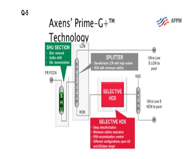
As I mentioned earlier, the high-octane value of the light coker naphtha makes it a good stream for blending into premium gasoline if the octane can be retained during desulfurization and is therefore a good fit for a selective hydrogenation unit, or SHU. The SHU will selectively saturate the diolefins, eliminating the potential for gums while preserving the high-octane olefin. Nearly all the light mercaptans, as well as a substantial portion of the light sulfides such as dimethyl sulfide (DMS), are converted to heavy sulfur compounds. The light naphtha is, therefore, functionally desulfurized and can be split out. If you look at the next slide, you will see an SHU process flow diagram. The naphtha flows through the SHU reactor where the diolefins are saturated and the light mercaptans are “shifted” to heavy sulfur compounds. The SHU reactor product then flows to a splitter where you can remove the light coker naphtha (LCN). This LCN can then be sent to a gasoline blending as a low sulfur component. The heavier portion from the splitter bottom, which includes most of the sulfur after the sulfur shift, is sent downstream to be desulfurized in a selective HDS (hydrodesulfurization) unit. The heavy coker naphtha, which commonly includes dimethyl disulfides, could alternatively be treated in a conventional naphtha hydrotreater and then sent to a catalytic reformer to recover the octane.
The heavy coker naphtha can be a burden for the conventional hydrotreater unit (NHT), especially if the NHT is designed for straight-run materials, as previously mentioned. Coker naphthas are really quite challenging feedstocks because they are laden with impurities and rich in sulfur and nitrogen. The high impurity loads, and more difficult desulfurization and denitrification loads can make this feedstock particularly challenging because typical straight-run naphtha hydrotreaters are not designed to provide sufficient severity. They are typically designed for lower pressure. They do not have the catalyst volume necessary to achieve the target cycle exit you might desire.
Alternatively, the heavy coker naphtha can be processed in the FCC gasoline selective hydrotreater, but with fewer synergies as compared to the light coker naphtha. Depending on the refinery configuration, co-processing of heavy coker naphtha with FCC gasoline can be practical when using Axens’ Prime-G+™ technology. Axens has successfully demonstrated this application in multiple refineries while maintaining normal unit cycle lengths.
JEFF BRAY and CHRIS ANDERLE (Honeywell UOP)
Coker C3/C4 olefins are usually processed with FCC olefins so that the value of the olefin content is captured. If there is no FCC, these olefins would be hydrotreated and routed with LPG. The coker naphthas (both light and heavy) are typically routed with the straight-run crude naphtha and hydrotreated in the naphtha hydrotreater. Coker naphtha does have olefins that have to be saturated in this unit, as well as having higher nitrogen and sulfur levels; therefore, the NHT (naphtha hydrotreater) requires a more robust unit design. The olefins will generate an increased exotherm that the unit design needs to accommodate to avoid mercaptan recombination. The dimethyl sulfides and disulfides are among the slowest reacting compounds removed in naphtha hydrotreaters, but they can be treated effectively if there is sufficient catalyst volume and pressure, producing naphtha that meets the low sulfur levels needed for reforming or blending. Where naphtha hydrotreating capacity is not sufficient to process this effectively, an alternative is to send it to diesel hydrotreating units. One issue with this approach is that the unit’s separation section needs to be able to recover the naphtha from the diesel. Most coker naphtha is processed in naphtha hydrotreaters. Once hydrotreated, coker light naphtha would go to the same destinations as the straight-run light naphtha including isomerization, gasoline blending, or naphtha sales. The heavy naphtha could go to reforming, gasoline blending, or naphtha sales.
Year
2016
Process
Question 6: What is your experience with having a vent depropanizer off-gas unit in order to manage tower pressure, and what might be the cause of and solution to the problem?
PHILOON (Honeywell UOP)
The typical and probably most obvious driver for the need to vent from a depropanizer column is the presence of Non condensable gases. Most commonly, this is ethane and ethylene that come in with the feed. The need to vent is more common in C3/C4 alkylation units as opposed to C4units. Even though the feed GC (gas chromatography) may show zero level of C2s in the feed, the limits of the analysis method may mask the presence of a significant, or at least notable, quantity of ethane and ethylene. Another possible Non condensable that may be present is nitrogen gas. This can be from the gas used to blanket fresh asset storage drums from some types of pump seals or other sources. The nitrogen is soluble in the acid, or it could break through when loading acid into unit. C4 alkys that get too many C3s in the feed may also have pressure control issues that can be ameliorated by venting. The C3 and C4 alkys have pressure problems if too much C3 material is allowed to accumulate in the unit. Another consideration is the overhead condensers. Exceeding the duty of these exchangers will raise the receiver temperature and, therefore, the column pressure. The elevated temperature can be a result of exchanger fouling or cooling water issues or from factors such as over stripping on the HF propane stripper.
KLEISS (Valero Energy Corporation)
The causes of frequent venting, as Steve mentioned, are typically insufficient condensing of propane or just too many non-condensables in the feed. Venting of the depropanizer can get expensive, as the vented gas is typically about 50% HF. If the propane is not condensing, cooling water flow and temperature could be the problem. Operating at higher isostripper pressure may also limit the venting. Most often, frequent venting is the result of noncondensables in the feed. This condition has happened at some or our refineries. The transfer of feed streams, both olefin and isobutane, with nitrogen or fuel gas should not be done. A Best Practice is to transfer isobutane and olefin by pump. Moving isobutane with fuel gas was an issue at one of our refineries. Routine GC analysis on the purchased isobutane to ensure light components, like ethane, are not too high is also a Best Practice. Typical units can generally tolerate a maximum of about 0.5% of C2 relative to the amount of propane in the feed. For example, if there is 10% propane in the feed, only 0.05% C2 can be tolerated. Adjusting the vapor flow in the HF stripper to maintain 30to 33% of the column feed will allow around 1% C2sto go out the bottom of the HF stripper. Over stripping will cause C2sto accumulate in the overhead. However, if the light material is methane, CO2, or nitrogen, it will need to be vented.
RON GATAN (Honeywell UOP)
Just a small comment about noncondensables. Moving up to the cat, even something as simple as tweaking the vapor-to-liquid ratio on the feed of the stripper in the gas condenser so that it is increased, as well as increasing the feed temperature, can result in dramatic improvement without getting rid of noncondensable to the alky, which I have seen.
RON GATAN (Honeywell UOP)
The typical and probably most obvious driver for the need to vent from the depropanizer column is the presence of a noncondensable. Most commonly, this noncondensable is ethane and ethylene that come in with the feed. This contamination is more a concern with C3/C4 alkylation units as opposed to C4units.Even though the feed GC may showa “0” ppm level of C2s in the feed, the limits of the analysis method may mask the presence of a significant quantity of ethane and ethylene.
Another possible noncondensable that may be present is nitrogen gas(N2). This can be from gas used to blanket fresh acid storage drums, from some types of pump seals, or from other sources. N2is soluble in the acid, or it can “breakthrough” from the storage tank when loading acid into the unit.C4 alkys that get too many C3s in the feed may also have pressure control issues which may be ameliorated by venting. Even C3/C4 alkys may have pressure problems if too much C3material is allowed to accumulate in the unit. Another consideration is the overhead condensers. If we exceed the cooling duty of these exchangers, the receiver temperature and the column pressure will increase. This problem can be as a result of exchanger fouling or cooling water issues or from factors such as over stripping on the HF/propane stripper.
Year
2016
Process
Question 7: How is propane content in the refrigeration loop optimized against the compressor capacity to minimize contractor temperature? Do you have a good process model to predict the optimum propane content?
KLEISS (Valero Energy Corporation)
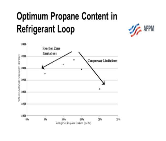
There is an optimum propane concentration in the refrigerant that will allow the alkylation unit to operate at a maximum alkylate throughput when the unit is up against limitations of both the compressor and the reaction zone heat removal capability. That optimum concentration of propane will vary from unit to unit and can be different seasonally. It can also be different from night to day or if exchangers are fouled, etc.
We received some information from STRATCO® where they reported that a Caribbean refiner, who was limited by reaction temperature, plotted daily alkylate production rate versus refrigerant propane content over a long period of time. Since the ambient temperature was relatively constant, the refiner was able to produce a scatter chart,similar to the one below.The chart shows that there was,indeed,an optimum propane amount in the refrigeration loop.STRATCO® has no model to predict this optimum. Producing a plot similar to the one below is the best way to try to optimize the propane content.
The Valero units typically operate at capacity with butylene feed, leaving limited room for feeding propylene. Therefore, there is not a lot of propane to remove from the system. The units operate with propane content in the refrigerant loop in similar ranges as those shown on the next chart. Valero has no process model to arrive at optimum propane content.
Year
2016
Process
Question 8: Do you have experience starting up an isomerization unit (an alumina chloride catalyst type) without first acidizing the reactor loop? What was the impact on catalyst activity?
JOCELYN C. DAGUIO (Honeywell UOP)
Honeywell UOP strongly recommends that acidizing of the reactor circuit should be included in the commissioning and startup of a new grassroots or revamped Penex™ or of Butamer™ units (isomerization units with chlorided alumina catalyst). If not, the consequence can be a significant amount of catalyst deactivation, as well as possible corrosion in the reactor section of the unit. A recent experience in which the customer elected to NOT complete the dry out and acidizing of a new reactor section resulted in an estimated deactivation of 60 to 85% of the new catalyst load.
For units undergoing a turnaround, the UOP guideline states that anytime equipment in the reactor circuit is exposed to air, it should be acidized. However, the actual scope of the work, how it is done, and the duration should be considered when determining if acidizing is required and the extent of the procedure needed. We are aware of units that suffered noticeable catalyst deactivation after restarting for a turnaround when acidizing was not done.
Acidizing is used primarily to prevent water from forming and deactivating catalyst, but it also serves an important function in preventing corrosion of the piping. The following outlines the mechanism for the generation of water during the normal operation of the unit. Acidizing the unit removes the source of the oxygen using the same mechanism, but before catalyst is loaded in the reactors.
1. The Penex™unit is constructed of carbon steel, so the pipe and vessel walls are mostly iron. When that iron is exposed to the atmosphere, it reacts with oxygen to form iron oxide. In new units, there is often a rust scale on the piping that has been exposed to air and moisture for months. After turnarounds, there should be much less scale, more like a light rouge coating of iron oxide on the piping or vessel walls.
2. During normal operation, the catalyst promoter PERChloroethylene (or PERC) is injected. PERC reacts with hydrogen in the presence of catalyst and heat to create hydrogen chloride (HCl). The HCl is carried throughout the reactors and through the heat exchange train and connecting piping. In the stabilizer column, the HCl is carried overhead into the caustic scrubber where the HCl is neutralized by the sodium hydroxide in solution. The HCl is necessary to maintain the acid sites on the catalyst so that the reactions will take place.
3.HCl reacts with iron to form iron chloride and H2. This is a harmless reaction; and in a dry environment, the iron chloride provides a protective layer to prevent exposed iron surfaces from further corrosive reactions.
4.The HCl will also react with iron oxide to form iron chloride and water; so, if rust is present in the reactor loop, water will be formed, resulting in permanent deactivation of some of the catalyst. Also, as iron chloride is soluble in water, when water is present, the protective iron chloride layer will breakdown and expose more iron to react with HCl. If water remains in the system, this cycle can continue until there is enough iron loss to result in a leak.
5.To prevent this corrosion, the piping is acidized with HCl before commissioning flow through the reactors and normal PERC injection. The iron oxide will be reduced to iron metal and water.The water generated must be drained from the system until the moisture readings indicate that the system is dry. Refer to the UOP General Operating Manualsfor more details on the acidizing procedure.
Year
2016
Process
Question 9: Describe your experience and application of advanced separation techniques, such as DWCs (dividing-wall columns), to reduce capital investment and operating expense.
KLEISS (Valero Energy Corporation)
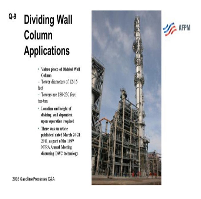
At Valero, we actually have several dividing-wall column applications. We have four in aromatics recovery service and one in a sat(saturated)gas plant service. The towers in aromatic service have been in operation between three and six years, and the tower in the sat gas service has been in operation since early 2016. All towers are meeting their design expectations. The dividing -wall towers have several advantages relative to the traditional sequential column designs. The first advantage is a smaller plot area and a lowerequipment count, which results in a capital savings of about 20 to 30%. The second advantage is a reduction in energy use of about 20 to 30%. The towers we have in aromatics recovery service are about 12 to 15 feet in diameter and about 230 feet tangent to tangent.

This slide shows a picture of one of the towers that is in aromatics recovery service. I noted on the bottom of the slide that there is an article published in the March 2011 NPR Annual Meeting papers that discusses the design and the contractor with whom Valero worked for the dividing-wall columns that were in the aromatic's recovery service.
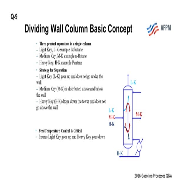
On the next slide, you can see a basic drawing of how the towers function. Instead of just having a light key and heavy key, you have individual light, middle, and heavy keys. One of the important process parameters is the feed temperature. It is critical in making sure that the light key goes up the tower and the heavy key goes down. The picture below is a graphic representation of how the towers basically work.
PHILOON (Honeywell UOP)
Honeywell UOP has been including dividing-wall columns (DWCs) in process unit designs, where they make sense, for a number of years with good success. We estimated and have seen significant reductions, as James was saying, in capital and operating costs on those columns. Most of the applications have been in benzene toluene fractionation in aromatics complexes or in linear alkyl benzene (LAB) detergent alky complexes. All of the columns with which we have been involved and which are operating have worked well, delivering the expected quality in each of the product streams with the predicted utility savings. The control systems have been able to deliver consistent products in generally robust operations. Recently, UOP completed the design of a dividing-wall column as a naphtha splitter in a naphtha complex. The overhead of the column is isopentane. The sidecut is a light naphtha (nC5and C6) that will be used as feed to a Penex™ isomerization unit, and the bottom is heavy naphtha that will be used as feed to a Platforming™ unit. This column is not yet in operation.
Year
2016
Process
Question 10: What strategies do you employ to meet cycle-length targets in naphtha hydrotreaters that are reaching catalyst activity limits due to capacity increases or feedstock quality decreases?
RHODES (Marathon Petroleum Company)
To increase cycle length on an NHT hydrotreater, the refinery needs to understand the contaminants that the reactor must handle and optimize the bed loading to maximize cycle length, as well as have the ability to handle the contaminant.
Silicon (Si) can be a big concern on NHT reactor cycle length. For the units that process coker naphtha, modification of the coker operation to minimize the injection of Si-based antifoams is key to improving cycle length. Si-based antifoams are used in the coker where the silicon will breakdown and end up in the naphtha fraction leaving the unit. Silicon can also be a factor in processing crude from various locations where Si-based antifoams are used. Understanding the amount of silicon, the bed has captured during a cycle will allow the refinery to minimize the amount of silicon traps that will be installed and maximize the use of active catalyst.
Arsenic is a strong poison for all hydrotreating catalysts. If the spent catalyst analysis shows high level of arsenic in the active catalyst bed, arsenic trap catalyst can be added into the catalyst bed to help capture arsenic and minimize the amount of arsenic that penetrates to the main bed of active catalyst. Using post-audits of the spent catalyst will help the engineers design the catalyst bed properly to protect the catalyst.
Maximizing the use of catalyst that has high surface area can increase cycle length for catalyst beds dealing with poisons. Active or regenerated catalyst typically has low surface area and can be very sensitive to poisoning, especially for Si. Regenerated catalyst typically has less surface area than the new fresh catalyst.
Finally, coking can be a concern on units that are operating at low pressure or at low hydrogen-to-hydrocarbon ratios, especially for units treating cracked naphtha or outside feeds. Therefore, maximizing the hydrogen-to-hydrocarbon ratio will help minimize coking issue.
STEVEN PHILOON (Honeywell UOP)
As a catalyst development, manufacturing, and sales business, Honeywell UOP continues to develop higher performance naphtha hydrotreating catalysts to handle our customers’ interest to run higher feed rates and utilize more difficult feeds. Moreover, we have developed next-generation catalysts that are more tolerant to contaminants in the feed, such as arsenic and silicon, along with the development of improved metals trap products to enable us to provide the most effective overall catalyst system.
For a specific unit, there is a not-always-obvious optimization with regard to the loading. There is a fixed volume that can be filled with hydrotreating catalyst, silicon or arsenic trap material, or grading/filtering material. Depending upon the operating factors that bring about the end of the cycle for a unit, the loading can be adjusted to maximize the cycle given the impact of those constraints.
RALPH WAGNER (Dorf Ketal Chemicals LLC)
Feedstock source and chemistry can have significant impact on hydrotreater catalyst performance. Phosphorous, mercury, and arsenic can reduce catalysts activity. Corrosion products, such as FeS (iron sulfide), can foul the catalyst in straight-run feedstocks. In cracked feedstocks, especially coker naphtha, unsaturated compounds may form polymers that can coke up on catalysts. Residual silica from silicone antifoam used in the delayed coker can also be detrimental. Strategies to sustain or increase cycle length targets include:
1.Implementation of a corrosion inhibition program –either by selection of materials of construction or chemical treatment or a combination of both –in the unit upstream can significantly reduce inorganic fouling. When using HTCI (high temperature corrosion inhibition) to process high TAN (total acid number) crudes, Dorf Ketal TANSCIENT™ can reduce phosphorous added to the crude by up to 80%.
2.Proactively determine metal content in the crude and develop a crude blending strategy to minimize the impact of metals. Dorf Ketal’s non-acid reactive adjunct desalter chemistry can supplement emulsion breakers fed to the desalter and remove iron and calcium to increase flexibility in the selection of crudes.
3.Implementation of a chemical treatment program containing antifoulant chemistry –which may include antioxidants, organic and/or inorganic (FeS) dispersants –has been proven successful in increasing the unit run-length.
Year
2016
Process
Question 11: What is your acceptable limit for organic chloride concentration in a naphtha hydrotreater feed? What are the possible consequences if this limit is exceeded?
CHRIS STEVES (Norton Engineering)
Chloride in naphtha hydrotreater feed can often lead to fouling and/or corrosion issues in the naphtha hydrotreater heat exchange equipment. Recommendations to keep chloride levels under 0.5 ppm in the feed are typical. If the target level is exceeded, then fouling and/or corrosion with ammonium sulfide and ammonium bisulfide salts may occur in the combined feed exchangers or the reactor effluent coolers. Facilities for intermittent washing of the CFE (combined feed exchanger) bundles may need to be installed to mitigate the impact of this salt formation, and metallurgical upgrading of the exchanger equipment may also be required.Topsoe Dual-Phase, Single-Stage Scale Catcher MHC (mild hydrocracking) unitcan be utilized to process either heavy gas oil or heavy gas oil blended with DAO (deasphalted oil). The unit typically has demetallization [HDM(hydrodemetallization)]catalysts in addition to high-powered/high-activity HdT(hydrotreatment) catalysts. The primary Topsoe technology for mildhydrocracking of heavy gas oil is the Haldor Topsoe Staged Partial Conversion (SPC). Additionally, catalyst selection will have a large impact on MHC operation. At low pressure operations, we recommend TK-947: Haldor Topsoe’s NiMo (nickel molybdenum)/zeolitic HDCcatalyst. At moderate pressure operations, select a NiMo version of a higher-zeolite HDC catalyst.The range of conversion and product selectivities is highly dependent upon the HDC catalysts selected. MHC is performed in units with pressures ranging from 850 to 1,600 psig (pounds per square inch gauge). Conversions range from 15 to 50%.
DENNIS HAYNES (Nalco Champion)
Due to the amount of ammonia typically generated in hydrotreating, evenvery low amounts of chlorides can drive ammonium chloride salt formation and result in fouling and corrosion. Any organic chloride in the feed should be avoided, if possible.
CANDICE CARRINGTON and STEVE PHILOON (Honeywell UOP)
The maximum allowable organic chloride in the feed to a naphtha hydrotreating (NHT)unit will mostly depend upon the solution used for the wash injected into the reactor effluent stream to control the pH of the aqueous phase that condenses between the feed effluent exchanger and the separator water boot. For an NHT unit with a simple water wash (the most common design), the limit of organic chloride in the feed is typically 20 ppmw. With this level of chloride, it will generally be possible to keep the pH of the water in the separator water boot between 5.5 and 6.5. When there is more than 20 ppmw chloride in the feed, it may become difficult to keep the pH of the water boot water above 5.5. As the water becomes more acidic, the rate of corrosion will accelerate. Therapid rate of corrosion may necessitate a redesign of the system to allow for the addition of a neutralizer into the wash water and possibly an upgrade in metallurgy between the feed/effluent exchanger and the product separator.
For NHT units with the capacity to add a neutralizer (e.g., most commonly, ammonia) to the wash water the typical limit of feed organic chlorides is around 50 ppmw while keeping the pH of the water-boot water above 7.5. Note that it is important to avoid pH between 6.5 and 7.5. In this range, the rate of corrosion spikes due to the interaction of chloride and sulfur on the metal surface. As above, the consequence of exceeding this limit is accelerated corrosion of the downstream piping and equipment, which can ultimately lead to leaks or loss of containment. There is an additional consideration in that some organic chlorides can be difficult to hydrotreat with only 80 to 90% of the chloride in the feed being removed across the NHT reactors. As a result, the chloride in the feed to the Platforming™unit may contain a quantity of chloride sufficient to impact catalyst chloride level.
Year
2016
Process
Question 12: What operating strategies do you employ to successfully regenerate catalyst in a continuous catalyst regeneration (CCR) unit with a carbon content in excess of 10 wt%?
MICHAEL CROCKER and STEVEN PHILOON (Honeywell UOP)
The burn zone in a Honeywell UOP Platforming™ CCR Regenerator is designed for operation at 5 wt% carbon on catalyst or about 5.25 wt.% coke at the design catalyst circulation rate. We find that most units can operate normally at coke levels 40% above the design (about 7.4 wt.% coke) and some at even higher levels of coke.
Note: The design coke-burning capacity is determined with a clean regenerator inner screen and 100% of design regenerator burn-zone recirculating gas flow. If the inner screen is fouled with catalyst chips and fines, and if the regeneration gas flow is less than the clean screen flow, then the coke-burning capacity of the regeneration tower will be reduced.
For most units and most circumstances, the recommended approach to deal with a high level of coke will be to operate the regeneration tower in black-burn mode at a reduced catalyst circulation rate. During this period of operation, there will be only upper air introduced into the burn zone; the rate of combustion air will be controlled to ensure that the peak burn-zone temperatures are kept below 1100°F (595°C). The rate of catalyst circulation is adjusted to keep the peak burn-zone temperature below the top TIpoint in the catalyst bed. The burn-zone profile should generally retain its normal shape. It is important that the observed peak temperature in the burn zone is NOT at the TI point in the catalyst bed. If this is the case, it is possible the real peak temperature is actually at a location higher in the bed and at a higher temperature. This can happen when the catalyst circulation rate is too low for the current regeneration gas oxygen level. Note that organic chloride should be injected into the feed of the platforming unit to help maintain the level of chloride on the catalyst while the regenerator is operating in black-burn mode.
In some circumstances, it may be necessary to allow the operation of the regeneration tower to shift to partial carbon burn. This will happen when the coke level on the catalyst exceeds the amount that can be burned, given the constraints of the maximum burn-zone peak temperature and the location of the peak temperature below the top TI. The lower portion of the burn-zone profile will not have its normal shape; the lower temperatures will rise as coke burning is continuing in that section of the catalyst bed. It may be that you are only reducing the coke on catalyst by 5 to 7 wt.%. If the catalyst entering the burn zone has 11 wt% coke, it may have 4 to 6 wt% as it leaves the regeneration tower.
The severity of operations on the reactor side should be moderated to reduce the rate of coke formation. Depending upon the level of coke and the severity of reactor side conditions, it may take several cycles in black-burn mode to reduce the coke level on the catalyst leaving the last reactor to a level that is low enough that the regeneration tower can be safely switched to white-burn mode.
It is important to limit the number of cycles that the regeneration tower operates in black-burn mode as the platinum on the catalyst is not redistributed when the chlorination zone is not operating normally with the regenerator in white-burn mode. At some point, the agglomeration of the platinum will begin to affect catalyst performance (activity and selectivity).It may take several cycles in white-burn mode to return the catalyst to its previous condition.
If you find yourself in a situation where the coke level on the spent catalyst is above 7.5 wt.%, UOP recommends that you contact your UOP Regional Service Manager to discuss the appropriate path forward. In special circumstances, other techniques such as dual zone burning have been used to deal with catalyst that has a high level of coke. The details of these alternatives should be discussed with UOP.
Year
2016
Process