Question 102: What benefits have you realized by installing packing in their FCC strippers? How did this equipment impact your catalyst circulation and unit pressure balance?
Year
2014
Process
Kenneth Bryden (Grace Catalysts Technologies)
While you would expect oxygen to mostly react with hydrogen to form water in a riser, some oxygenates do form.
Phenols and other oxygenates can form in the riser via two mechanisms-
•Cracking of molecules in the feed that naturally contain oxygen bonded to the aromatic structures (for example: phenols, benzofuranes and quinolones)
•Reaction of extraneous molecular oxygen with hydrocarbons in the riser.
Sources of extraneous molecular oxygen in the riser include:
•oxygen carryover that is entrained in the catalyst from the regenerator
•oxygen from using air as the aeration media for the regenerator standpipe
•air entrained or dissolved in the feedstock
Since increasing reactor severity will result in an increase in catalyst circulation, it is likely that the increased oxygenate production being observed is from the higher catalyst circulation which is increasing the entrained molecular oxygen carryover to the riser.
The responses to question 106 at the 2006 NPRA Q&A and Technology Forum and question 91 from 2013 AFPM Q&A and Technology Forum contain additional information on this topic.
David Strangmeier (NALCO Champion)
Monitoring parameters of the FCC such as density and height of catalyst beds, gas and/or solid distribution of the cyclones, air distributor, slide valves and standpipes are accomplished through measurements of pressure, pressure drop and temperature at various locations. These measurements are indirect. Gamma scans (density measurements) and tracer studies (flow and distribution of gas and/or solids) will provide real time direct measurement for improved diagnosis and troubleshooting around the riser, reactor, stripper, regenerator, and standpipes. A well-planned benchmark test can help to document the before and after effects of design or operational changes.
Specific examples include:
• Identify mal distribution of catalyst at the air grid
• Gamma scan to evaluate dip legs, flapper valves, and bed levels
• Main Fractionator Gamma Scans to identify damage, fouling, flooding, entrainment, or weeping
• Radioactive gas tracing of the stripper for hydrocarbon carries under detection
Minh Dimas (CITGO)
One of our refineries has developed limits for pressure drop through the reactor circuit. The maximum allowable pressure drop is determined by the difference between the upstream reactor or heat exchanger design pressure and the set pressure of the relief valve on the high-pressure separator. The purpose of the alarm is to ensure that the upstream vessel’s design pressure will not be exceeded before the pressure at the downstream relief valve reaches the set pressure.
Tim Lewer (Shell)
Pressure drop limitations across the high-pressure section of a hydrotreating unit are common in refineries. They can be set for many reasons, including but not limited to
1. Equipment design – High pressure separators are controlled to provide the proper suction pressure to the recycle compressor. If the reactor and exchanger train build high pressure drop, the maximum allowable pressure in those vessels may be exceeded in order to maintain the proper high pressure separator pressure. A pressure drop alarm may be set to avoid exceeding the upstream equipment design pressures.
2. Reactor catalyst monitoring – High differential pressure alarms are common for entire reactor trains if individual catalyst bed pressure drop indication is not available. This is important for catalyst health monitoring, especially if guard beds are not present. In addition, reactor internals may have specific differential pressure limitations.
Exchanger fouling detection – It is not typical to have a lot of pressure or temperature indication on the feed/effluent exchanger train so it can be difficult to detect exchanger fouling.
Martin Gonzalez (BP)
The buildup of system pressure would push a centrifugal recycle compressor back on its curve, so setting a pressure drop limit across the entire reactor circuit would help prevent compressor surge.
Martin Gonzalez (BP)
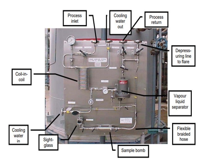
Inter-reactor sampling can be important for monitoring catalyst performance, troubleshooting, and measuring yields. In a hydrocracker, such a sampling system allows measurement of nitrogen slip from the pre-treat section into the hydrocracking stage. Several technology licensors offer designs for inter-reactor sampling. It is important for the system to be closed loop, venting to a safe low-pressure location such as a flare. Use of a sample pot with relief valve protection can allow use of closed sample bombs and quick-connects at lower pressure than the high-pressure reactor loop. It is useful for sample pots to have level gauges, pressure gauges, and temperature indication. Water-bucket-and-coil arrangements are typical for cooling the process stream. Be cautious of introducing permanent connections between utilities and process, such as when nitrogen is used for flushing, because this may lead to overpressure and intermixing. Valves used should be designed for repeated operation against high differential pressure. Reliability of root valves can be improved if procedures are sequenced to avoid opening and closing these valves against full differential pressure. A photo of an inter-reactor sampling system is shown here. Note that it may be desirable to have the sample container in a vertical orientation, rather than horizontal as in the photo. Please also refer to Safety question 1 of the 2008 Hydroprocessing Q&A Session, which addressed a similar issue.
Tim Lewer (Shell)
Taking inter-reactor or reactor effluent samples in a high-pressure hydroprocessing unit has many risk factors that need to be considered when designing the sample system. In many cases, plants have decided to remove or not use existing sample stations due to the risk. Where high pressure sample systems are used, there are a few common design considerations in addition to the previous discussion:
1. The sample system needs to be designed in such a way that the sample collection point and operator position while opening/closing the valves are sufficiently far apart to remove the operator from the line of fire if there were a release of high-pressure gas or H2S. This is often overlooked, but all high-pressure sample systems should be evaluated for this concern (i.e. recycle gas samples).
2. Clear operating procedures and specific operator training. The valve opening and closing procedure can even be posted as a fixed sign at the sample station to be read each time a sample is taken.
Minh Dimas (CITGO)
HTHA is a form of degradation of metal caused by hydrogen reacting with carbon in the metal to form methane in a high temperature environment, typically above 400 deg F and 50 psia H2 partial pressure. The methane gas accumulates in the grains and voids and expands to form blisters. This weakens the metal strength and initiates cracks in the metal. Alloys of particular concerns are carbon steels, ½-Mo and ½-Mn steels, and 1-Cr alloy.
We evaluate all of our hydrotreaters for HTHA, using normal operating data and short-term excursion data (such as hot H2 strip). We plot the H2 partial pressure and temperature on the Nelson Curves to determine the likelihood for HTHA to occur. Most of our equipment operates on the safe side of the Nelson curves due to higher alloys. For equipment with C-½ Mo material, we increase the inspection frequency to look for HTHA, which may be difficult to detect with conventional NDE and may required specialized techniques for early detection. We also plan to upgrade the metallurgy of an exchanger that has a carbon steel channel head but clad with stainless steel.
Martin Gonzalez (BP)
API Recommended Practice no. 941 “Steels for Hydrogen Service at Elevated Temperatures and Pressures in Petroleum Refineries and Petrochemical Plants” gives the well-known Nelson curves against which temperature and hydrogen partial pressure of equipment can be evaluated. It is common in the industry to apply safety margins of up to 50 deg F on temperature and 25-50 psi on hydrogen partial pressure.
Installing temperature instrumentation between shells or channels of heat exchanger banks in high pressure hydrogen service may be helpful for providing assurance that conditions do not fall above the Nelson curves. Fouling should be taken into account as it may result in significantly different operating temperature than assumed in design. Consideration should also be given to transient operating conditions such as when taking one of a pair of exchangers out of service, opening or closing bypasses, and periods of operation with hydrogen-only, as this may cause temperatures to increase to a level above the Nelson Curve. Consider also replacing C-½ Mo piping with higher alloy steels.
Shankar Vaidyanathan (Flour)
For older reactors, especially those in service beyond their initial design service life, a good risk management approach is to investigate whether the cumulative time spent at the short-term conditions falls below the HTHA incubation curves. Refiners maintain a database of equipment and piping operating close to HTHA conditions. This is used in fatigue evaluation studies, equipment and piping recertification, remaining life analysis, and to set inspection priorities while defining long-term maintenance needs. In some cases, study has shown that replacement of C-½ Mo with upgraded material is justified. Positive material identification procedures will help to avoid improper material substitution at turnarounds. Ensure technical reviews of metallurgy, operating pressure and temperature alarm settings when a unit is recertified for use under conditions different from the original design.
Tim Lewer (Shell)
HTHA is a function of hydrogen partial pressure, temperature, and metallurgy.
1. Reactor Effluent Train – The effluent train must have the proper design to ensure temperatures are below HTHA temperature prior to any metal spec change. Be aware of creep, where-by process improvements, debottlenecking, and heat integration changes can move the HTHA critical temperature downstream past the metal spec change (i.e., 1¼ Cr changes to carbon steel).
2. HTHA is time dependent – Longer exposure to temperatures above the Nelson curve will increase the risk.
3. Abnormal periods – All unit conditions must be evaluated for risk of HTHA. Create a spreadsheet with all piping or equipment that is above the HTHA pressure. Define the maximum temperature and maximum hydrogen partial pressure cases, and evaluate versus the Nelson curve. Log the instruments used to monitor the unit temperatures and pressures and create appropriate alarm limits or operating procedures.
Shankar Vaidyanathan (Flour)
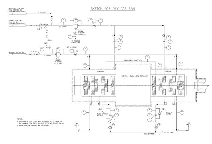
Dry gas seals have been used for compressors for many years. The feedback was mixed in its infancy, and there were teething problems. External factors such as the contamination of the sealing gas, insufficient sealing gas pressure and process gas leak onto the seal ring surfaces have been the main reasons for seal degradation. Wetness, particulates, and heavier hydrocarbons cause seal reliability issues. The quality of seal gas and buffer gas, dryness level, pretreatment, liquid separation and filtering are the keys to reliable operation. Experience has shown that seals can last a long time in a clean environment and many existing plants have switched over to gas seals. Tandem self-acting dry gas seal with internal labyrinths has been selected in many recent projects.
Please see the attached sketch for external components of the dry gas seal system.
1. Depending on pressure balance, the sealing gas may be pure makeup hydrogen (if the makeup compressor is located within the same plot) or recycle compressor discharge gas. Chlorides in makeup hydrogen and amine aerosols in recycle hydrogen are potential contaminants.
2. Nitrogen is used as the buffer gas.
3. Filters for seal gas and buffer gas should be duplex, one operating and one standby, 3-micron stainless steel coalescing filters equipped with high differential pressure alarm. Avoid three-way valves for filter switching.
4. Consider additional pre-filter for sealing gas if experience has shown that coalescing filters are inadequate. Consider additional demister filter for buffer gas if necessary.
5. Minimum 1” size stainless steel piping is preferred. Additional notes for piping layout include minimizing runs, avoiding pockets, heat tracing and winterizing as necessary.
6. The seal gas injection is on automatic pressure control.
7. Primary vent is routed to flare; secondary vent is routed to safe atmospheric location.
8. Primary seal vent flow is monitored with high flow and high-pressure alarms.
9. Pressure in the secondary vent line must be limited such that the maximum seal backpressure should not exceed 5 psig.
10. Consider differential pressure alarm between the buffer gas and secondary vent.
Minh Dimas (CITGO)
Dry gas seals are more reliable than oil seals provided the seal gas conditioning system is properly designed, and the seal gas is very clean and dry. That said, the filtration and liquid removal system must be very reliable and have spare equipment to maintain its reliability. Tandem dry gas seals require a source of very clean, dry seal gas at startup.
Shankar Vaidyanathan (Flour)
The nature of the hydroprocessing unit is such that a wide range of molecular weights are possible for the recycle gas from nitrogen at start-up to hydrogen with increased light ends during normal operation. While the treat gas requirements are pre-determined, quench gas demands vary during normal operation with varying chemical hydrogen uptakes and emergency situations. A recycle compressor that has the flexibility to operate in such an environment by changing the speed of the driver has an inherent advantage. The choice between motor and turbine drive is decided by the process safety considerations, refinery steam balance, the reliability of the electric power source, and capital and operating costs. Automatic depressuring is a standard design for hydrocrackers.
First, let us look at the turbine drive. Turbines are selected by plants where steam is readily available at reasonable cost. The high speed turbine can be directly coupled to the high speed compressor and can provide the operational flexibility. Turbines can have higher overall system reliability. Turbine drives can offer additional protection during power failure to cool the reactor and to sweep oil out of the high pressure exchangers and charge heater. Backpressure turbines avoid surface condenser and large cooling water load. Initial installation cost may be higher for turbine. Superheated steam is required. Turbines are more maintenance intensive. The steam supply survivability in case of overall refinery power outage should be factored in the selection process.
Now let us look at the alternative of electric motor drive. Motors are selected by steam balance constrained refineries where a reliable electric supply is available at a cheaper cost than steam. Motor efficiency is higher and it needs less maintenance. The initial investment cost may be lower. The electric drives on charge pump and recycle compressor may preferably be supplied from separate reliable power sources. A gear box is required between the motor and the compressor to match the speeds. Motor has a high starting current requirement. Single fixed speed motor with suction throttling is inefficient. A two speed motor as a minimum provides the operating flexibility. A more preferred option is a 60-100% variable speed drive. It provides safer margin away from surge and saves operating cost. It can provide constant torque capabilities thus lowering the acceleration and deceleration effects on mechanical components during transient conditions. It helps to reduce the startup stress on the motor and also allows increased frequency of restarts. Voltage fluctuations in electric supply should be considered in the motor design.
Two types of variable speed motor drives are variable speed hydraulic coupling and variable frequency drive (VFD). The variable speed hydraulic coupling is cheaper compared to VFD, more efficient due to power splitting and occupies less plot space. The complexity, hence, the reliability and the overall system cost should be evaluated while considering a VFD. A VFD over 1500 HP should have a dedicated heat removal system.
Martin Gonzalez (BP)
For measuring chloride in feed stream, some of our refineries use an instrument based on Monochromatic Wavelength Dispersive X-Ray Fluorescence (MWD XRF), for which nitrogen and sulfur offer no interference. The instrument measures total chloride, whether organic or inorganic. The relevant ASTM method is D7536.
Tim Lewer (Shell)
Organic chloride can be measured by removing the inorganic chloride from the sample by water washing, followed by chloride determination of the sample using either combustion Ion Chromatography (IC) or monochromatic wavelength dispersive x-ray. Both instruments are being used within our refineries and have been applied to a number of refinery streams. Nitrogen and sulfur do not interfere with either technique.
Minh Dimas (CITGO)
One of the most currently used methods is ASTM 779, which has nitrogen and sulfur interference at concentration greater than 0.1%. There are other ways to measure chloride using combustion; it can be a titration or an Ion Chromatography (IC). Neither one has a large sulfur interference. The Combustion IC (ASTM 991 recently developed by UOP) is fast becoming the preferred method and is specific to chloride in the analysis so interferences are absent. The tricky part is optimizing the combustion to avoid coking of reactor tube and possible plugging.
