
Question 8: Where is salt (NH4Cl or (NH4)2S) fouling most likely to occur? What are common practices for monitoring and mitigating?
ABIGAIL SLATER (HollyFrontier)
Salting typically occurs in the reactor effluent exchangers (shell and tube and fin fans), recycle and net gas compressors, and product stabilizer overhead system (top trays, overhead condenser, etc.). Common monitoring practices on exchangers and fin fans can be tracking exchanger duty, temperature, and delta pressure, all of which indicate increasing fouling. For compressors, the discharge flow, efficiency, and delta head (corrected for gas molecular weight) can all be indicators of compressor fouling. For stabilizer towers, tower delta pressure and similar overhead exchanger monitoring can indicate fouling.
Common practices to mitigate the fouling are to reduce the source of the foulant, which includes reducing nitrogen in the feed and chloride in the products using technologies like chloride guard beds. For compressors, continuous naphtha washes can be effective at managing fouling. For towers and exchangers, online and offline water washes can remove salt formations. In Naphtha HydroTreaters, online water washes can also be effective in removing salt fouling with no major impacts to the unit. In Naphtha Reformers, online washes can also be effective but must be done in parts of the unit where the water will not contact the catalyst (downstream of reactors and recycle compressor). If no online mitigation is possible, the unit will periodically need to be shut down to clean the affected equipment.
THOMAS PORRITT (Chevron U.S.A.)
We find that salt deposits form in the compressors, the reactor effluent fin fans, the stabilizer column overhead fin fans, and the stabilizer top trays (see figure Q8 – 1). Process temperature is the largest factor in where the deposits are most likely. There are two approaches the user can take to monitor and mitigate salt deposition. One is proactive the other is reactive.
The user can prevent salt deposition by choosing to operate their process above the sublimation temperature of the salt being monitored. For exchangers or coolers, the user can also monitor the fouling rate. For compressors, the user can track compressor efficiency. Once fouling rate or efficiency have declined to unacceptable levels the user can mitigate with one of the methods described below.
If the user cannot practically monitor the indicators above, there are some additional reactive monitoring they can employ. For heat exchangers or coolers, the user can monitor the approach temperature and the differential pressure. For compressors, the user can monitor vibrations. For distillation columns, the user can monitor differential pressure and flooding in the top of the column. These indicators are less effective as they only manifest once salt deposits have begun to impact the process.
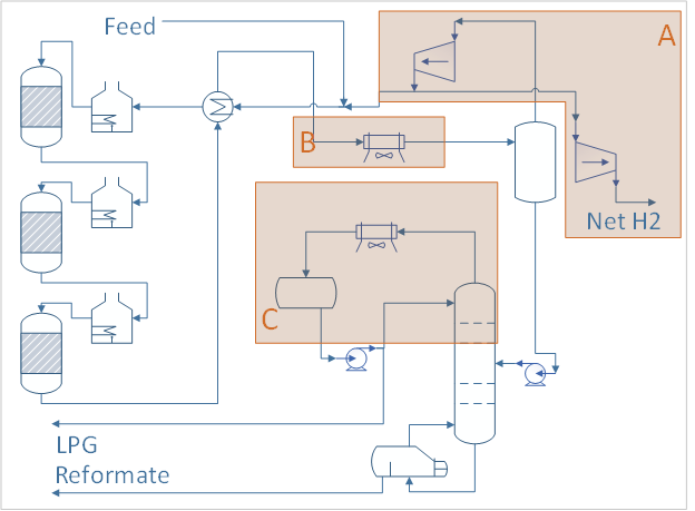
Figure Q8 - 1 Common Areas for Salt Deposition
The user has some preventative and reactive options to mitigate the effects of salt deposits in the process. The best option is to control species that form the salts. Most users limit nitrogen in the feed because it addresses both the ammonium chloride and the ammonium bisulfide salts. For compressors, the user can supply a film on the rotors in the form of a coating or a continuous naphtha wash to prevent salts from gaining a foot hold. For reactor effluent coolers or distillation overhead coolers a continuous water wash can remove the salts before they build up. For distillation columns a chloride scavenger has been proposed by some vendors.
For existing units and equipment where continuous washes or coatings are not an option, the user will need to periodically shut down for a water wash to remove the salts when they build up.
Year
2019
Process
Question 9: How do you track chloride in liquid/gas/LPG? What are your criteria for replacing adsorbent in chloride treaters?
DAVINDER MITTAL (HPCL Mittal Energy)
Chlorides have been a long standing issue in catalytic reformer operation. Until a few years ago, the focus on preventing operational problems from the chloride compounds in the catalytic reformer product stream was to remove HCl. More recently, a growing concern for many refinery operators has become the removal of organic chloride species besides HCl. These compound are less easy to detect and measure and also less readily adsorbed or absorbed. The effectiveness of the available chloride guard products is limited although significant improvements have been made and are being made to the formulations.
Total chloride tracking and removal presents a different challenge which requires amended chloride guard formulations that can either co-remove HCl and organic chloride compounds or alternatively a combination of two materials, one specific for each problem.
Adsorption of organic chlorides is competitive with other components in the process stream. HCl is more polar than RCl and is likely to preferentially adsorb on many surfaces. Thus the adsorbent may be effective when relatively new while both HCl and RCl are removed. The more efficient HCl removal may occur in the bed inlet zone while RCl removal further down but RCl breakthrough will occur as HCl front moves down the bed and starts to displace RCl as the active surface.
Many Refiners struggle to accurately measure chlorides in CCR liquid streams/LPG. The best practice is to use detector tubes (say Drager 0.2/A) of correct range for detection of inorganic chloride/ HCl in gas (applicable for H2 and LPG in gas phase). Correct range means, if expected range is 1 ppm for example, detector tube should be of range 0.2 to 5 (preferable) or 10 at Max. Using larger range tube possess the risk of losing accuracy of measurement due to higher measurement interval/least count.
For both liquid and gas samples, care should be taken to choose appropriate sample container. Suitable metallic bomb with PTFE coating is suggested to avoid chloride interaction with metal and wrong measurement. Sample collection point should be short and copper tubing to be avoided. Ensure that sample point is hot while collection. Perform detection tube analysis as quickly as possible.
UOP 910 method is for determining total chloride in gaseous hydrocarbons or liquefied petroleum gas (LPG) at concentrations ranging from approximately 1 to 1000 mg/ml(milligrams per milliliter) for gas or mass- ppm for LPG(liquefied petroleum gas). Except for fluoride, other halogens present are calculated as chloride. Chloride cannot be determined quantitatively, if sulfur is present at concentrations greater than approximately 1 mass%.
UOP 930 method is for determining sum of organic chlorides and Hydrogen chloride(HCl) in LPG and Refinery Gas streams at concentrations ranging from approximately 0.02 to 1000 mass –ppm (mg/Kg) for LPG(liquefied petroleum gas) samples or 0.02 to 1000 ng/ml for gas samples. Other halogens present are determined as chloride.
For detection of total chlorides in liquid (applicable for Reformate/Isomerate), ASTM D 7536 is another – uses MWDXRF analyzer to detect chloride content of sample.
Alternatively, HCl content of liquid sample can be tested by OXY-HYDROGEN COMBUSTION of sample and combustion product are absorbed in a dilute solution of sodium carbonate. The chloride ion in aqueous absorber solution is titrated by potentiometry with standard silver nitrate solution (IFP-9316).
If liquid phase chloride testing capabilities are not available, the alternative option is to analyze LPG sample in vapor phase. It is important to ensure that sample is fully vaporized so that an accurate measurement can be made. Once the sample is in gas phase, detector tube technology can then be used to determine the concentration of chlorides present. Keep in mind the concentration results using this method will be in ppmv. It is recommended to convert the concentration back to ppmw as is customary for liquid applications.
Analysis, and particularly speciation of organic compounds at low ppm level is not trivial. A number of specialized techniques can be used which include oxidative coulometry and gas chromatography with an electrolytic conductivity detector. Methodology has been developed by specialist companies to use gas analysis tubes for detection of total chlorides and HCl.
In order to determine when a chloride treater should be changed, a routine sampling protocol could be established. This sampling can include periodic measurement of the chloride concentration on both the inlet and outlet of the chloride guard bed. The inlet sample analysis would allow for calculation of the expected saturation of the chloride media. The amount of chloride that can be absorbed prior to breakthrough can be estimated based on the expected capacity of the material for a particular application. The expected capacity can be provided by the absorbent supplier. The outlet sample analysis would confirm whether or not breakthrough has occurred.
As sampling can be cumbersome, another option would be to only take baseline chloride measurements and then calculate the life of the bed based on expected capacity. The baseline chloride concentration and flow rate across the bed over time can be used to calculate expected or residual life of the bed.
A corroboration for chloride at inlet of guard bed can be made through reformer chloride balance once a while. Chloride intake at LPG treater inlet is estimated based on balance and can be used in conjunction with the review of past spent absorbent analysis. A determination can be made as to the appropriate time to make the change out on the absorbent without experiencing any breakthrough. Change out can then be scheduled to occur during a downtime that is close to the time breakthrough is expected to occur.
Concerning adsorbent replacement of chloride treater, when arranged in LEAD-LAG position, the best time is to plan for replacement is when chloride content of effluent at the outlet of LEAD treater vessel reached a value @ 10% of inlet chloride concentration. Keeping more time in service the LEAD bed, though Refiners can maximize the left over adsorbent life but it possess threat of over- chloriding of alumina due to excessive HCl loading, thereby increasing risk of polymerization/green oil formation if olefins are present in streams (for example CCR hydrogen rich gas).
For a standalone chloride adsorber, it is better to replace as soon as it crosses guaranteed cycle length under normal operation or as soon as chloride break through appears if this guard bed is exposed to some upset operation. For standalone chloride guard bed, additionally use sample point a few places within the absorber bed. From a practical view point, since chloride analysis at inlet and outlet of chloride guard bed is not followed regularly, it is difficult to estimate end of life and refiner may keep an emergency spare to avoid operating a guard bed without any remaining adsorbent life and contaminating downstream equipment and tanks with chloride.
THOMAS PORRITT (Chevron U.S.A.) (3)
Metal-catalyzed coke or MCC is formed on the metal surfaces of the reactor internals. It is also known as filamentous coke or rod coke. It is enhanced by high temperature, low hydrogen partial pressure and zones of low velocity. MCC can be prevented by passivating the metal surfaces. Most users do this by injecting an organic sulfide in the feed that converts to H2S in the process. The H2S then interacts with the Chromium in the metal surface to form a passive layer of chromium sulfide. A good rule of thumb for the sulfur injection in traditional high-pressure naphtha reformers is 0.25 – 0.5 ppmw based on the feed. For low pressure units the user should consult their technology licensor for appropriate targets.
BILL KOSTKA (AXENS NORTH AMERICA)
Although HCl is the most abundant Cl-containing species in reformer effluent streams, organic chlorides (RCls) will also be present in lesser amounts due to acid-catalyzed reaction of olefins with HCl. Removal of both HCl and RCls requires guard beds containing one or more adsorbents. Failure to trap RCls and quantify their breakthrough may lead to downstream corrosion and fouling issues since their breakthrough precedes that of the more easily trapped and quantified HCl.
Leakage rate of chlorides from the reformer increases as its catalyst incrementally loses surface area with each regeneration. Lower-surface-area catalyst requires a lower H2O/HCl ratio in order to maintain constant catalyst chloride content. Chloride addition to the catalyst must be increased in the regenerator to obtain the requisite lower H2O/HCl ratio since H2O concentration remains relatively constant. This increased chloride addition to the catalyst results in an equivalent increased loss from the catalyst once back on oil that will shorten chloride adsorbent lifetime.
Lower catalyst surface area also hinders maintenance of critically important platinum dispersion. Loss of platinum dispersion increases olefin production which along with higher HCl content can increase RCl formation as the catalyst ages. Higher RCl formation further accelerates the loss of chloride adsorbent lifetime. Catalysts with higher surface area stability extend the lifetime of downstream adsorbents, units and equipment.
Samples of liquid streams can be analyzed in a laboratory using a variety of standard methods including microcoulometry, extraction + potentiometry, MWDXRF and CIC. As listed in the following table, each technique detects specific chloride species and has different levels of quantification (LOQ).
|
|
|
||||||||||||
Samples of gas streams are typically analyzed in the field with indicator tubes; however, more accurate measurements are made in the lab using a different set of standard methods. A good sampling system and technique are critical for achieving the requisite accuracy. Gas phase monitoring techniques are summarised in the following table.
|
Chloride Species Monitoring in Gas Phase |
|||
|
Standard Method |
Technique |
Chloride Species Determined |
Limit of Quantification (LOQ) |
|
UOP 910 |
Microcoulometry |
Total Chloride |
1 ng/ml (gas) 1 wppm (LPG) |
|
UOP 930 |
Pyrolysis + Dry Colorimetry |
Organic Chloride + HCl |
0.02 ng/ml (gas) 0.02 wppm (LPG) |
|
Scrubbing + ASTM D512 |
Scrubbing + Water Analysis -Mercurimetric Titration -Silver Nitrate Titration -Ion Selective Electrode |
HCl |
|
|
ASTM D4490 |
Indicator Tubes |
HCl Vinyl Chloride Trichloroethylene |
Tube Dependant |
Examples of indicator tubes are listed in the following table. Note that cross sensitivities and the presence of various RCl species will interfere with the accuracy of the tubes used to measure RCls, but should afford determination of chloride breakthrough.
|
Indicator Tubes for Gas-Phase Analysis |
||
|
|
Gastech |
Dräger |
|
HCl |
Ref 14 L 0.2-76 ppm |
Ref 81 03 481 0.2-20 ppm |
|
Vinyl Chloride |
Ref 131 La 0.25-54 ppm |
Ref 81 01 721 0.5-30 ppm |
|
Trichloroethylene |
Ref 132 LL 0.125-8.8 ppm |
Ref 67 28 541 2-250 ppm |
Ideally, chloride adsorbents should be changed once RCl breakthrough occurs to ensure chloride-free operation of downstream units and equipment. Determination of chloride breakthrough based solely on HCl measurements may lead to months of undetected RCl leakage. Time-based replacement of chloride adsorbents is typically based on HCl breakthrough and also can lead to months of RCl leakage.
Zhen Fan (Norton Engineering Consultants, Inc.)
To prevent metal catalyzed coking, make sure that a low concentration of H2S (~1.5 ppm) is maintained in the recycle gas. Consider injection of DMDS to the reformer feed if feed sulfur from the upstream naphtha Hydrotreater is extremely low.
Year
2019
Submitter
Process
Question 10: What causes metal-catalyzed coking (MCC) that obstructs catalyst circulation in CCR reformers? What actions do you take to mitigate MCC formation?
BILL KOSTKA (AXENS NORTH AMERICA)
Metal-catalyzed coke (MCC) formation typically occurs on 3d valence transition metals such as iron and nickel. Under CCR-like conditions of low hydrogen partial pressure (less than about 620 kpa), high temperature (more than about 480 °C) and low or stagnant flow, hydrocarbons can adsorb and completely dissociate on these metals. The resulting adsorbed, dissociated carbon can then dissolve into and change the metal structure. Once a nanosized portion of the metal becomes supersaturated with carbon, carbon begins to precipitate in a tubular crystalline form breaking the carburized-metal fragment away from the parent metal with the carbon nanotube continuing to grow between them. Despite their fragile appearance, these carbon nanotubes are incredibly strong and can readily damage equipment when present in sufficient numbers.
Mitigation of filamentous carbon growth is best achieved by reducing the possibility of hydrocarbon adsorption on the problematic iron surface. Two methods have been used to successfully achieve this goal in CCR reformers: 1) passivation of the metal surface with an adsorbate such as sulfur and 2) use of a more appropriate metallurgy.
Research done by HJ Grabke et al. has shown that very little sulfur, about 0.5 wppm in the naphtha feed, is required to adequately passivate the metallurgy of a CCR reformer. As a result, most CCR reformers are operated with roughly 0.5 wppm sulfur in the feed. Some refiners may rely on incomplete naphtha pretreatment to supply this sulfur, however, addition of a known amount of a sulfur-containing species to the feed ensures adequate passivation on a continuous basis.
Carbon steel is very vulnerable to MCC formation. Alloying carbon steel with increasing amounts of chromium and molybdenum reduces this vulnerability. These two metals tend to migrate to the steel’s surface and greatly dilute iron’s presence there. As a result, there are much fewer Fe-Fe neighbors necessary for hydrocarbon adsorption, dissociation and dissolution into the steel structure. A 9Cr-1Mo alloy steel greatly reduces MCC even at 650 °C. Utilization of this alloy with on-oil sulfur injection virtually eliminates MCC even at 650 °C.
DAVINDER MITTAL (HPCL Mittal Energy)
The catalyst circulation in CCR may be obstructed due to other reasons as well besides metal-catalyzed coking (MCC). However, the metal catalyzed coking presents a serious problem especially in low pressure CCR reforming units.
The processes of metal catalyzed coke formation will cause particles of the heater tube metal to break away from the tube surface. There is also an increased risk immediately following replacement of heater tubes. The coke formed in the furnace tubes may eventually migrate to the reactors and lodge behind the scallops or baskets. These coke deposits can grow until the scallops or baskets are deformed, affecting catalyst circulation, unit performance or even leading to an unplanned shutdown.
The recommended approach is to generally operate the Naphtha Hydro-treating (NHT) unit to remove essentially all of the sulfur in the feed. This will ensure that other contaminants (nitrogen, metals, oxygenates, etc.) are also removed from the feed to the extent achievable by the NHT. Organic sulfur is then added to the CCR reformer unit feed with a chemical injection system pumping in a specific and controlled amount of organic sulfur compound to achieve the target recommended by the licensor. This provides the refiner with independent control of the sulfur in the feed to the unit that can be changed as needed if feed rate or operating conditions change.
Our Continuous Catalytic Regeneration Reformer Unit was commissioned in May’2012. However, within one year of operation, the unit started experiencing several performance issues including restriction of catalyst flow in some of the spider legs of all 04 reactors , higher pressure drop and lower endotherm in reactors (more severe in 2nd Reactor, 60-70% of design value) and lower RON than design.
In view of the above issues, it was decided to shut down CCR during March-April’2014 and inspect reactors. Significant unexpected damage of reactor internals was found.
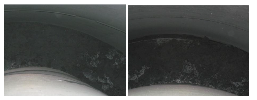
Picture-1: Huge quantity of coke in annular space between reactor grid and shell
Picture-2(a): Last panel of outside reactor grid found fully bulged with huge coke build up
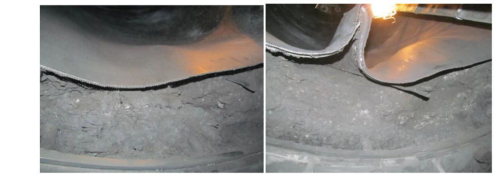
Picture-2(b): Last panel of outside reactor grid found fully bulged with huge coke build up
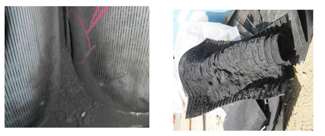
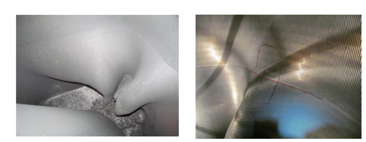
Picture-3(a): Shiny coke between and inside scallops leading to bulging and fish mouth cracks

Picture-3(b): Shiny coke between and inside scallops leading to bulging and fish mouth cracks
A joint root cause analysis with Licensor confirmed presence of Fe and carbon graphite (high carbon content) in the coke samples. During cleaning of the scallops, presence of lot of hard shining coke (metallic coke) was observed along with soft coke. It was concluded that coke build up in reactors/scallops/grids may have taken place due to metal catalyzed coking considering problem with DMDS dosing pump during initial year of commissioning as well as due to other reliability issues like frequent trip of recycle gas compressor. The presence of metallic coke in reactors may have acted as nuclei and further catalyzed the coke growth during recycle gas failure.
The heater tube thickness measurements also indicated some loss of thickness indicating metal catalyzed coking in addition to other forms of coke. The level of thickness loss was fortunately not alarming to inhibit future operation.
Based on root cause analysis certain recommendations were made to minimize metallic coking and damage to reactor internals.
Metallic Coke:
Maintain sulfur level 0.3 to 0.5 ppmw on CCR feed to be substantiated by presence of detectable amount of H2S in recycles gas and 100-150 ppmw of ‘S’ on catalyst sample.
Operate Naphtha Hydro-treating (NHT) unit to remove essentially all of the sulfur and other contaminants in the feed. Inject DMDS in CCR feed through dedicated facility to maintain recommended range of sulfur.
No flame sweeping/scattering on the furnace coils.
Maximum Tube Metal Temperature (TMT) to be restricted below 620oC.
Operation of heater burners within the design regime (maximum allowable process absorbed duty per burner: 1.0 Gcal/h).
Perform positive material identification of tube metal to confirm P9 (confirmed).
Other Coke/ catalyst agglomeration due to coke:
Improvement in reliability of recycle gas compressor.
Check for cold spider legs and try to restore catalyst circulation
Check for quality and temperature of net gas from CCR to avoid condensation in reactor spider legs
Maintain recommended coke ( 4 -5 wt%) on spent catalyst
Stress build up in Reactor internals:
Carry out emergency catalyst circulation in case of unplanned trip of the Recycle Gas compressor to relieve the mechanical stress built up due to difference in the thermal expansion coefficient between catalyst and reactors internals.
Year
2019
Submitter
Process
Question 11: Where are your liquid-phase chloride treaters installed for reforming units? What are the advantages of each location?
BILL KOSTKA (AXENS NORTH AMERICA)
Liquid-phase Cl treaters are typically used in three locations for reforming units.
Treating the unstabilzed reformate stream provides several advantages. The stream is heated upstream of the stabilizer column which ensures that any ammonium chloride is dissociated into HCl and ammonia allowing HCl removal and eliminating the possibility of ammonium chloride issues in the stabilizer. A treater at this location eliminates the need for separate treaters on the stabilizer offgas, LPG and stabilized reformate streams. If done properly, one large treater can replace three smaller treaters. Locating the treater between exchangers in the stabilizer’s feed-exchanger train affords conditions that guarantee liquid phase operation instead of less desirable two-phase operation obtained at higher temperature. Liquid phase flow is better for chloride adsorption.
If the unstabilized reformate treater cannot be properly designed to efficiently remove all Cl species, then treatment of the stabilizer’s individual effluent streams becomes necessary, especially where problems have been encountered or, in the case of new units, where the licensor’s experience suggests that a problem is likely.
Year
2019
Submitter
Process
Question 14: What are your strategies to reduce alky acid consumption?
ABIGAIL SLATER (HollyFrontier)
The most impactful parameter affecting alky acid consumption is feed quality. Reducing feed contamination will greatly reduce acid consumption. There are also operational changes that can be made to reduce acid consumption, but the biggest impact will be feed contaminants. Anything that will cause the alkylation reaction to reduce acid strength or polymerize will affect acid consumption.
There are several different feed contaminants that can affect acid consumption, and several strategies to combat these contaminants. For HF alkylation, sulfur can be a large factor in acid consumption. Sulfur, in the presence of the HF alkylation reaction, produces light Acid Soluble Oil (ASO) which can be difficult to remove from the unit. Generally, a low rerun temperature can get rid of the ASO, but it will result in additional free acid with it. Some strategies to remove sulfur in the feed is Fluidized Catalytic Cracking (FCC) feed pretreatment (hydrotreat), caustic skid treaters, and amine scrubber technology.
The presence of ethane in the feed, particular to HF alkylation, will make ethyl fluoride and cannot be alkylated. Ethyl fluoride is then vented from the Alky and the fluoride molecule is not recovered. FCC upstream fractionation or a de-ethanizer fractionator are strategies to reduce ethane in the feed.
Carbon chains higher than five carbons can cause polymerization during the alkylation reaction, which increases acid consumption and reduces alkylate production. Similarly, dienes have double bonds which tend to break and make longer fluorocarbon chains (polymerization) and reduce alky production and increase acid consumption. This can also be combated by proper upstream fractionation.
A typical contaminant for HF alkylation is water, or any molecules containing the hydroxide (OH) grouping (No CO, Aceto-Nitriles, ethers, esters, ketos, etc.) This includes caustic that can be carried over from the sulfur and mercaptan feed treating systems (caustic skids). The most common strategy to remove water is solid state feed driers (typically mole sieve or activated alumina). Mole sieve may last longer than alumina treaters as it can retain more water. Some refiners will also install an upstream water wash system, which is designed to absorb any molecules containing the OH group prior to entering the alky feed drying section.
Operationally, ensure that the reactor riser temperatures are within the designed range. If the riser temperature is too hot or too cold, acid consumption will increase. Incorrect riser temperatures tend to produce more polymerization reactions (ASO). Ensure that the isobutane to olefin ratio (HF specific) is within design range.
RICK DENNE (Norton Engineering Consultants, Inc.)
For sulfuric acid alkylation units, tight control and monitoring of spent acid strength is key. Acid titration should be performed on each shift (centrifuging of the acid is a must before titration). The online spent acid strength indication (Coriolis meter) should be checked against the laboratory results on a monthly basis by the unit engineer.
For HF acid alkylation units, tight operation of the acid rerun/regeneration column is required. Consider infrequent gamma scans of the column and/or hydraulic study to determine tray performance and condition.
For both technologies, feed containments should be minimized. Good sulfur and water removal as well
as butadiene saturation should all take place in the feed pre-treatment section.
Year
2019
Process
Question 15: What practices and modifications have you implemented in response to the new High Temperature Hydrogen Attack (HTHA) guidelines and updated Nelson curves?
JOE RYDBERG (CITGO)
The primary source document for dealing with High Temperature Hydrogen Attack (HTHA) is API Recommended Practice 941 – Steels for Hydrogen Service at Elevated Temperatures and Pressures in Petroleum Refineries and Petrochemical Plants. This document provides the basic guidelines for determining the risk of HTHA in equipment that operates at elevated temperatures. At elevated temperatures and pressures experienced in refining operations, hydrogen at the surface of a metallic interface will be first adsorbed and then absorbed into steel. Diffusivity into steel is highly dependent upon a number of factors including: microstructure, alloying elements, and current temperature. Upon entering the steel, hydrogen can react with carbon or carbides to form methane. Methane, being too large to permeate through the steel is trapped in the microstructure, leading to the numerous damaging effects collectively known as High Temperature Hydrogen Attack leading to internal decarburization, fissuring, and eventually cracking. API 941 summarizes the results of experimental tests and actual data acquired from operating plants to establish practical operating limits for carbon and low alloy steel in hydrogen service at elevated temperatures and pressures. This API Recommended Practice does not address the resistance of steels to hydrogen at lower temperatures (below about 400ºF), where atomic hydrogen enters the steel as a result of corrosion or by electrochemical mechanisms.
The document contains a graph that shows the Nelson curves for carbon steel and low alloy steels. These curves are used to determine the risk of HTHA occurring in various grades of steel. This curve has been moved to lower hydrogen partial pressures and temperatures throughout the years as more industry data has come in. If you plot the temperature and partial pressure of hydrogen for the process on this graph and the point plotted is below the specified metallurgy’s curve, HTHA will not occur. This graph also shows that HTHA doesn’t occur at hydrogen partial pressures below approximately 50 psia, except at extremely elevated temperatures. Also shown on this graph is a curve for C-½Mo that was formerly used in the industry. However, several failures have occurred in C-½Mo equipment below this curve. After a number of failures occurred, API decided that the C-½Mo curve should no longer be used, and instead it was required that the carbon steel curve be used for C-½Mo. The newest edition of API 941 does contain a section that deals specficially with C-1/2Mo equipment, which takes into account a number of fabrication methods and testing data to determine the resistance of the material for analysis.
While 400ºF is the common deciding parameter for the threat of HTHA, 350ºF was taken to be the alarm temperature in order to have a more conservative safety factor during the initial screening of equipment and piping at CITGO Lemont. If a piece of equipment or piping was noted to be operating above this temperature, its temperature history was investigated to see if thermal excursions occur that could potentially lead to HTHA. After the equipment that operates above 350ºF criteria was established, the hydrogen partial pressure was obtained from Operations for these areas. Using these two pieces of information, the conditions for this piece of equipment were plotted on the Nelson Curve for their particular metallurgy. Potential for HTHA was then determined for that piece of equipment from the location on the Nelson Curve.
Most of the piping near the new Nelson curves has been replaced in the past with an alternate metallurgy, though there are some that still fall near, but below the curve. If operating above the curves, then replacement is suggested on the next turnaround opportunity. All vessels composed of C-1/2Mo material were replaced pre-emptively, rather than continue to inspect using uncertain techniques.
Current Nelson Curves in API 941, 216 Edition.

ROBERT STEINBERG (Motiva Enterprises)
API Recommended Practice 941 “Steels for Hydrogen Service at Elevated Temperatures and Pressures in Petroleum Refineries and Petrochemical Plants” was updated in 2016 with a new Nelson curve for non-PWHT carbon steel. The new non-PWHT curve is about 50°F lower than the old curve that is still used for non-welded or PWHT carbon steel.
The new Nelson curve is used the same way as the old curve. Many refiners limit their maximum operating temperature to 50°F below the curve.
Once the new curve was in place it was necessary to review all carbon steel lines and equipment in hydrogen service. For non-welded and welded with PWHT steel there was no change. For areas where the new Nelson curve had to be applied the following options were utilized:
• For equipment that was still operating safely below the new Nelson curve no changes were needed. If there was a high temperature alarm to keep from exceeding the Nelson curve it was adjusted.
• For equipment that was operating relatively close to the Nelson curve limit, additional monitoring was put in place to ensure temperatures remained in an acceptable range. In some situations, additional thermocouples were added, generally a strap on skin thermocouple, to allow continuous monitoring. Alarms were also configured and operating procedures updated to ensure temperatures stayed below the Nelson curve.
• In a limited number of circumstances, it may be necessary to upgrade metallurgy (generally changing from carbon steel to 1¼Cr – ½Mo) to stay below the Nelson curve. Where this is needed, additional monitoring and risk assessments are performed until the equipment can be upgraded.
LARS JORGENSEN ( Haldor Topsoe)
The new API-941 guidelines, from February 2016, have been implemented regarding material selection, and any carbon steel now requiring PWHT will be specified as such. Generally, this has not been a major cost issue since many clients already specify PWHT requirements on all high-pressure carbon steels.
MAX LAWRENCE (Shell Global Solutions)
In existing facilities, equipment and piping operating above the revised Nelson Curves have been identified and scheduled for inspection and evaluation. Shell’s evaluation applies a safety factor on the Nelson Curves. If inspection reveals that HTA is present, the piping or equipment is identified for replacement at an appropriate priority. If HTA is not present, the inspection for HTA will be repeated periodically.
For new facilities, the established material selection protocols are followed using the revised Nelson Curves.
CHRIS WOZANIAK (Honeywell UOP)
UOP is a sitting committee member of API 941. In 2012, UOP implemented the use of post weld heat treatment (PWHT) on carbon steel operating slightly below the API 941 7th edition carbon steel curve. In 2016, API 941 released the 8th edition, which contained a new curve for carbon steel, and the existing carbon steel curve was designated as carbon steel plus PWHT. Since 2016, UOP has been exclusively using the 8th edition of API 941. Historically, UOP has always been conservative for specification of materials in high temperature, high hydrogen partial pressure environments by not setting metallurgy using operating conditions. UOP has always used the design temperature and hydrogen partial pressure set by the design pressure (H2pp = DesP * mol% H2), which provides additional safeguard when picking metallurgy that is resistant to high temperature hydrogen attack (HTHA).
Year
2019
Submitter
Process
Question 16: What is required to achieve Safety Integrity Level 2 (SIL-2) rating on the hydrocracker depressuring system? For a hydrotreater that does not require SIL-2, what position should the depressurization valve fail to?
JOE RYDBERG (CITGO)
CITGO typically seeks process safety consultants to help with SIS design including SIL selection. Kenexis is such a company who has provided the following technical information regarding depressurization systems.
There are a multitude of different initiating events (loss of recycle gas, reactor internal failure, coking, catalyst loading errors, etc) that can cause a runaway to occur, and a wide variety of options for dealing with the runaway reaction, depending on its severity. Furthermore, safeguards that are effective against one initiating event might not be effective for another and some of the safeguards are only partially effective. Also, some of the safeguards share equipment items, which further complicates a LOPA. Due to the complexity of this hazard some operating companies have chosen to go beyond a traditional LOPA for picking SIL targets all the way to a more quantitative analysis using fault tree. In this analysis we have determined that the typical shutdown design which will allow tolerable risk to be achieved includes two depressuring valves. These depressuring valves are typically sized for low rate (150#/min) and high rate (300#/min). Operationally, you would trigger the low rate first and try to get the process back under control and if that fails, go to the high rate. Also, the sizing will vary based on licensor, Shell and Chevron licensed technology varies from what is stated above which is for the UOP Unicracker, but they’re in the same ballpark.
The initial reason for the two separate valves was not reliability requirements to achieve a SIL target. There were two valves in this application way before SIL was invented. The licensors saw that thermal runaway was a problem, and in order to decrease reaction rate you need to decrease pressure (thereby decreasing concentration of reactants). Opening either the low rate or high rate depressuring valves will cause the process and unit to dramatically shift. Opening the high rate depressuring valve can be particularly impactful, potentially causing reactor or flare system damage. While one or two high rate depressurings is not expected to significantly damage the reactor vessel, the process licensors generally take great care in preventing a spurious activation of the depressuring valves, especially to the high rate valve.
In order to prevent spurious activation of the high rate valve it is typically an air-to-open valve. Air to open depressuring valves are allowed and compliant with IEC / ISA 61511, but when used require additional consideration specifically, back-up “power” and alarms on loss of utility. This usually takes the shape of a volume bottle and check valve combination on the instrument air supply (sized for 3 strokes usually), and a low pressure alarm on the volume bottle. While some apply this same design technique to the low rate valve, not everyone does because the consequence of activating the low rate valve is not as severe. That said, there is nothing wrong with using the same air-to-open design as the high rate valve.
On an additional note, we are currently seeing many refiners revisit the choice of a high-rate and a low rate valve. In recent years, the activity of hydroprocessing catalysts and severity of hydroprocessing has increased. Many of the scenarios that previously were controlled with a low-rate depressuring now require the high-rate depressuring. As a result some in the industry are considering the use of two high-rate valves instead of the low-rate / high-rate combination. It is common that the combination of two depressuring valves - 300#/min and 150#/min automated with temperature bed sensors and a SIL2 rated logic solver are required to get to SIL 2 for most hazard scenarios for the valve system.
Returning to CITGO’s experience, for all the hydrotreaters in the CITGO system, there are remote manual depressurization or dump valves. After reviewing approximately fifteen HDT’s in the CITGO system, the de-pressurization valves are fail closed.
For the hydrocracker, there are two dump valves, a smaller valve (when opens, de-pressures the unit at a rate of 100psi/min) and a larger valve (when opens, de-pressures the unit at a rate of 300psi/min). The larger dump valve opens when the recycle compressor shuts down or when reactor bed temperature indicators hit 825F. The smaller dump valve opens when reactor temperature indicators hit 800F. The hydrocracker is also outfitted with a third “manual” dump valve to flare. The de-pressurization valves are fail closed.
API recommended practice 521 discusses the need for de-pressuring systems for both temperature runaway and to protect equipment against stress rupture from fire, particularly in systems that operate above 250psig in vapor only service. The following factors should be recognized to ensure reliability of the valve during a fire:
• Valve size, de-pressuring rate
• Failure position (specifying FO) and reliability– flare capacity should not be exceeded to avoid environmental impact (note – multiple unit flaring could occur when there is a loss of instrument air)
• Redundant air, N2, or bottles for valve actuation
• Location, fire protection, accessibility during a fire
MAX LAWRENCE (Shell Global Solutions):
SIL-2 requires robust SIL-2 components throughout the input -> solver -> output activation chain. Multiple (voting only when identical) inputs are generally available for a dedicated high-reliability computer separate from basic control. The chief difficulty is in achieving SIL-2 reliability for the output – depressuring valve(s). There are two general approaches: redundancy and testing. Location factors and precise details will determine which is most suitable. Failure mode should be determined by SIL analysis, but at least one depressuring valve should be fail-open (i.e., air to close) to handle the instrument-air failure case.
For a hydrotreater that does not require SIL-2, it is prudent for at least one depressuring valve be fail-open (i.e., air to close) to address the instrument-air failure case.
CHRISTINA HAASSER (Honeywell UOP)
In a hydrocracker, a UOP design specifies low and high rate depressuring valves. The SIL 2 rating is on the High Rate Depressuring valves. UOP designs for SIL-2 rating by having two valves in parallel. There are provisions to allow each of the valves to be independently blocked in to permit a full stroke test of the valve. This arrangement allows one valve to still be in service protecting the unit while the other valve is tested. Since the majority of the pressure drop is across the orifice plate, having two valves in parallel does not change the depressuring rate significantly.
Testing interval is another aspect of meeting SIL-2 requirement. UOP has maximum testing intervals that our system designs are based on. Final testing intervals are dependent on customer requirements and local regulations.
For Hydrotreaters, UOP design has a single rate of depressuring and the valve is specified to be Fail Closed because the catalyst in a hydrotreating unit is not usually as active as hydrocracking catalyst and is not expected to experience an immediate temperature excursion upon loss of recycle gas. Therefore, there is no incentive to provide automatic depressurization on loss of recycle gas. If the recycle gas compressor can be restarted without too much delay, operation can resume without having to re-pressure the unit. The operator always has the option to initiate depressuring if the situation requires it.
UOP designs Hydrocracking Low Rate Depressure valve as Fail Open. This low rate depressuring valve opens upon loss of Instrument Air. The intent is to prevent a temperature excursion in the event of a plant wide instrument air failure. The high rate depressuring valve is Fail Closed. If required, the operator always has the option to manually initiate high rate depressuring because of instrument air reservoirs that are sized for at least 3 strokes of the valve.
LARS JORGENSEN( Haldor Topsoe)
Initiators and final elements for auto depressurization are designed according to the International Electrotechnical Commission (IEC) standard 61511 and must fulfill SIL-2 capability. Initiators will typically be 1-ouf-of-X high-high temperature readings in the catalyst bed or reactor skin temperature. Spurious trips are reduced by having low-scale burnout. Another initiator is typically the loss of treat gas, which is done to avoid stagnant hot liquid. Spurious trips for this flow measurement are reduced by a 2-out-of-3 philosophy in which two measurements should read low-low flow. A high axial temperature difference and/or rate-of-change over the catalyst bed can add another level of protection.
For a hydrotreater, with less than SIL-2 requirements, the depressurization valve will be designed as fail-open to ensure functionality on loss of instrument air. This valve would be a manual activated system. To reduce the risk of spuriously failing open, the system will be provided with a safe-air bottle and a low instrument air pressure alarm (this also applies for hydrocrackers). Additionally, two solenoids in series to prevent shutdown if one solenoid fails can be considered if allowed by Layers of Protection Assessment (LOPA).
Year
2019
Submitter
Process
Question 17: What testing frequency and additional feed characterization (apart from bulk properties) should be used to accurately monitor catalyst performance on heavy feeds?
FERNANDO MALDONADO (Shell Catalysts & Technologies)
The type and frequency of tests performed are unit and refinery specific. When creating or modifying a unit’s laboratory test schedule some factors to be considered include:
1. Unit objectives
2. Past and/or current operational issues
3. Refinery onsite laboratory’s capability and resources
4. Catalyst vendor support
At many refineries, there is a heavy demand placed on refinery laboratory resources and a request for adding new test(s) results in the question as to which of the current test(s) will be dropped from the schedule. Additionally, for non-routine operational issues, the catalyst vendor can often provide specialized feed and product sample testing useful in troubleshooting exercises.
To monitor catalyst performance on a unit processing heavy feeds (e.g. FCC PT), Shell Catalysts & Technologies suggests the following laboratory analysis:
1. Tests to be performed daily on the feed and products:
a. Feed density, sulfur, nitrogen, distillation, concarbon, and metals (nickel, vanadium, iron, sodium, silicon)
b. VGO product density, sulfur, nitrogen, and distillation
2. The following tests should be done on at least a weekly basis:
a. Feed aromatics, and C7 insolubles
b. VGO product aromatics, concarbon, and metals (nickel, vanadium, iron, sodium, silicon)
JOHN PETRI (Honeywell UOP)
ASTM D6352 is used for simulated distillations of higher boiling point feeds including DAO. Simulated distillation better captures the tail end of a feed distillation than an ASTM D1160 or D86 distillation. Some bulk analyses that refiners may not consider include silicon analysis since flow improvers are now more commonly used in production and transport of heavier oils. For bitumen based crude sources a particle size distribution analysis using laser refractometry will be important to size and select graded bed materials properly for pressure drop mitigation.
UOP recommends occasional HRMS and GC-GC for hydrocarbons type distribution can be used to quantify multi-ring aromatic components such as 4 and 5+ rings, which can be highly inhibiting and coke forming. In addition, for recycle operations you should analyze for PNA and HPNA using appropriate advanced analytical methods such as HPLC and UV absorbance methods. The frequency can be related to significant changes in crude selection or changes in distillation operations that increase the endpoints of feed streams.
SERGIO ROBLEDO (Haldor Topsoe, Inc.)
For proper catalyst monitoring we like to see daily analyses for sulfur, nitrogen, gravity and distillation (SimDist) of the bulk feed. We also like to have feed contaminants (Ni, V, Si, etc.) measured, at minimum, on a weekly basis.
Olefin and, in particular, diolefin content of each individual stream is important to know. Lighter molecules and olefins can react with fast kinetics. To keep these reactions in a controlled range requires understanding the catalyst bed dynamics and the concentration of each. Ideally this should be done daily, but as at a minimum on a weekly basis.
Aromatic content and aromatic breakdown (mono, di, tri+) is also important to analyze to understand how much hydrogen consumption and, in turn, volume swell can be expected from each stream. We recommend this be done on a weekly basis, but at a minimum, on a monthly basis for each stream component.
C7 insolubles, or asphaltene content, should also be measured on a weekly basis.
Year
2019
Submitter
Process
Question 18: What are your methods to mitigate bed 1 pressure drop without a unit skim? How would your approach be different if the pressure drop developed in a different bed, say bed 3?
JOE RYDBERG (CITGO)
Mitigation of elevated pressure drop first begins with identification the nature of the pressure drop. Is the DP a result of a more gradual buildup or a step change from a unit event or upset? Was an event related to hydrogen starving of the unit or loss of recycle compressor?
The source of the fouling could be identified and controlled. In one instance, a corrosion inhibitor had been identified to have been turned off and once it had been restored, the DP leveled out. Alternatively, improved filtration has be added (10 micron to 1 micron) to mitigate pressure build if delta P is building due to particulates.
Iron Sulfide fouling: There is Iron Agglomerant chemical injection applications that can be used to mitigate pressure drop. These need to be applied very carefully and require injection quills, carrier fluid and careful monitoring. If the foulant is iron sulfide, they can work very quickly but if they are more organic in nature, they will not be effective. This is typically a last resort method that does not resolve the DP issues but extends run a couple months.
Crust Layer: Introducing an upset condition could break up a crust layer, opening up new flow pathways. If a reactor system is very sensitive to mal-distribution and temperature excursions (hydrocracking), this should be used with extreme caution. One application, a diesel hydrotreater, showed some success by employing a two-compressor operation (normal operation was one reciprocating compressor).
Coke: Hot hydrogen strip as early as possible to remove soft coke formed.
Mitigation tactic: Reduce hydrogen to oil rate can be especially effective but should be done carefully, risk of coking and higher catalyst deactivation.
DP in bed other than top: Employ H2 quenches or temperature control to lower bed operating temperature. This may be helpful if the DP build is related to coking to limit additional coke build. Temperature/flow shock the bed using quench hydrogen available. Slowly reduce all quench H2 to the bed, then quickly open the quench to rapidly cool the bed.
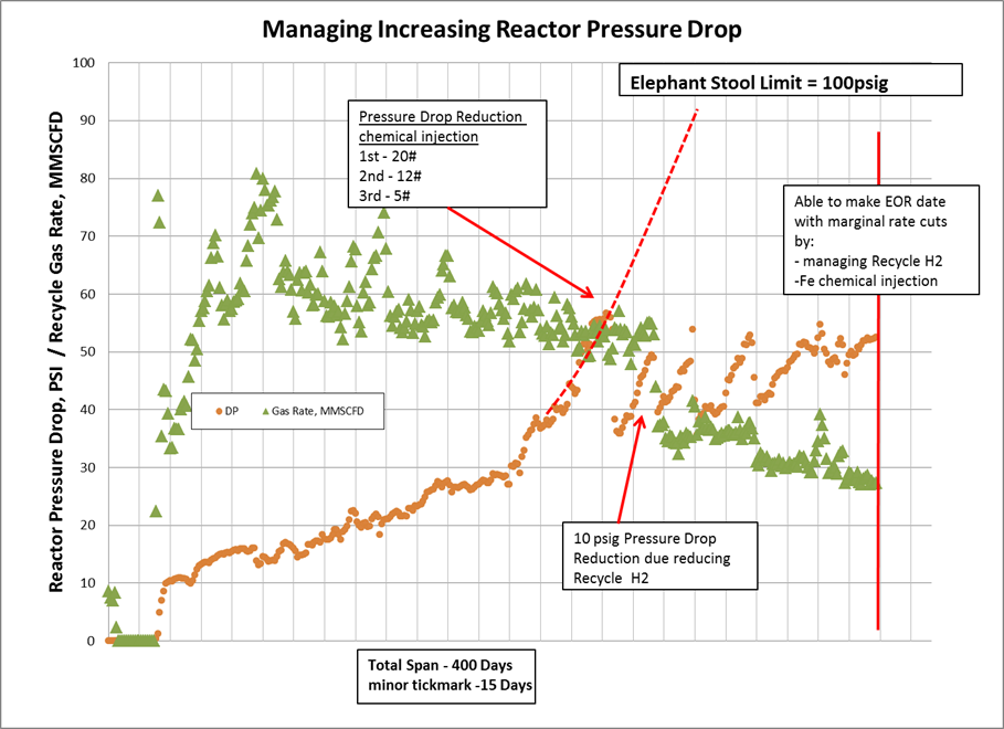
For example in a Naphtha Hydrotreater, both recycle H2 and Fe Injection agglomerant chemistry was used to extend cycle length. Compressor spillback was used to reduce hydrogen forward flow (caution need to ensure compressor stays away from surge).
ERIC LIN (Norton Engineering Consultants, Inc.)
High pressure drop in bed 1 is normally caused by contaminants in the feed that may not be picked up by the feed filters due to insufficient specification. Whereas most hydrotreaters can get by with simple cartridge filters, hydrocrackers can generally benefit from an automatic backwash-type feed filter. These filters generally use either UCO or filtered feed as a backwash medium and the process is automated by a high pressure drop setpoint.
If the high pressure drop were to occur beyond bed 1, then the ratio of graded catalyst in each bed should be calculated. If the ratio is greater than 2.5:1 from one layer to the next (i.e. active catalyst to support catalyst or support to larger support), then there exists the possibility that catalyst is migrating from bed to bed. If the ratio is fine, then the reactor internals, specifically the redistributors after quenches, require attention. The Licensor would have designed the reactor internals to accomplish a preferred flow regime and to minimize the pressure drop between beds. As most reactor internals are proprietary, a consultation with the Licensor is typically required.
VERNON MALLET (Honeywell UOP)
Methods of mitigating bed 1 and lower beds pressure drop can best be described as a process of identification of those factors either collectively or individually contributing to the pressure drop issue. Generally, bed 1 pressure drop escalation can be identified as feed processing (which may include feed types, feed contaminants and amount and type of contaminant), mechanical related or catalyst related. Pressure drop issues related to lower beds are much more difficult to identify and therefore during operation it is difficult to lessen or mitigate the impact.
Bed 1 pressure drop issues related to feed processing can be lessened or mitigated by first identifying the root cause upstream of the hydroprocessing unit. Identification of contaminants requires extensive lab analysis of the various feeds that hydroprocessing units process in the cycle due to continuous changes in refinery crude slates or changes in upstream feed processing unit operations that provide varying feeds to the hydroprocessing unit. Identification of feed contaminants and monitoring changes to the upstream unit operations during the cycle may indicate opportunities for adjustments that lessen the impact of increasing pressure drop to allow the cycle to continue. Identification of feed contaminants will also provide valuable detailed information of various contaminant levels so that a robust graded bed system can be provided for bed 1 either during the cycle via a mid-cycle skim or developed for subsequent cycles. Upstream processing units providing various feed sources to hydroprocessing units may also experience higher than normal corrosion which would result in increased amounts of iron or other corrosion products that would impact bed 1 and possibly lower catalyst bed pressure drop.
Identification of particular refinery crudes that result in feeds with higher than design levels of contaminants (metals, asphaltene, and carbon residue) should be undertaken to determine root cause of pressure drop. Feed types that are more reactive resulting in polymerization and condensation to occur may also be contributing factors. Identifying particular crudes as contributors and processing these would then need to be economically evaluated against removing these crudes or conducting a mid-cycle skim or continuing the cycle at reduced feed rates to achieve the desired cycle and turnaround timeframe. Reduction in recycle gas rate will also lower apparent bed pressure drop, although a large move may accelerate rate of coking reactions.
There are chemical additives designed to reduce top bed pressure drop which in some cases have demonstrated a degree of success. A better approach is to implement a guard bed strategy which will help manage unforeseen causes of top bed pressure drop.
Identifying the cause and mitigating the impact of increasing pressure drop in lower catalyst beds of a hydroprocessing reactor is more difficult during the cycle. However, there are possible scenarios that can contribute to increasing pressure drop in the lower beds. Generally, catalyst fines are swept from the catalyst beds and removed from the reactor by the liquid and gas. This is also true for small micron size particulates such as iron sulfide. Inertia is the driving force for this particulate removal. However, what can occur is the driving force or inertia starts decreasing as the rate of vaporization increases down the reactor resulting in these smaller particulates depositing in the quench zones or lower catalyst beds. Operating with highly reactive feeds that have a higher amount of coke precursors condensing to form coke, operating at low hydrogen partial pressure in lower beds and asphaltene precipitation are also possible causes of bed pressure drop increase in the lower beds.
SERGIO ROBLEDO (Haldor Topsoe, Inc.)
The methods available to mitigate pressure drop are dependent on what the cause of said pressure drop is. Generally speaking, lowering treat gas rate will lower the pressure drop through a catalyst bed. This will of course, not reverse/correct the pressure drop but will only buy the refiner time to plan a catalyst skim or replacement. Lowering feed rate will also reduce the pressure drop, but that is usually not an attractive option due to the economic implications.
Depending on the feed type, and operating conditions, another option would be to lower the feed temperature to bed 1. This will reduce the amount of feed that vaporizes, which will directionally lower pressure drop in the bed; however, this lower reaction rate will have to be compensated in downstream beds which will lead to uneven catalyst deactivation rates.
Iron Particulates
One of the major culprits of pressure drop build-up is particulate solids that enter with the feed. As mentioned in question 21, engineering the addition of a feed filter, if one is not already present, can dramatically impact the pressure drop build profile. Despite crude desalting and feed filtration, solids may still be present in the feed. If a filter is already in place, the plant personnel should investigate changing the micron size of the filter element. It is important to keep in mind that these elements are sized either as nominal or absolute basis. An absolute size filter will not allow anything above the micron size it is rated for to pass through, whereas a nominal filter will include an efficiency rating or degree of filtration. An absolute size filter essentially has 100% efficiency in preventing particles larger than its rated size micron. Usually, a change from nominal to absolute will improve the build profile during the cycle. The material of the filter element could also be changed, but the refiner should check with their filter supplier for the appropriate solution. However, these changes may require more frequent element change-outs and/or backwash frequency. The refiner will have to decide what is feasible from a maintenance schedule standpoint when changing to a smaller size micron filter, or filter type.
Some of the frequently encountered bad actors are:
• Corrosion products (iron scale and debris)
• Catalyst fines or dust
• Coke fines
• Sediments
• Salts (Na, K, etc.)
• Large carbonaceous scale spalled from the furnace or heat exchangers
If pressure drop is a result of iron particulates, there are chemical additives that can be injected with the feed to agglomerate the iron in the catalyst bed. This will open pathways for the liquid/gas to flow through and lower the pressure drop across the bed. Typically, this has diminishing returns during each subsequent dosing. This method is also a means to extend cycle length to allow the refiner to plan a catalyst skim/change-out and will not completely solve the pressure drop issue. Check with your chemical supplier for appropriate chemical in their respective portfolio.
Carbon Accumulation
Pressure drop arising from carbonaceous accumulations in the catalyst bed may be reduced by applying a ‘Hot Hydrogen Strip’ and/or a ‘LCO Flush’. Haldor Topsoe can furnish both procedures. Alternatively, depending on the nature of the issue, certain commercial additives may be added to the feed that are intended to reduce fouling and/or pressure drop caused by carbonaceous based foulants. As before, check with your chemical supplier for the appropriate antifoulant technology.
Ensuring that the hydrogen partial pressure is maintained at recommended levels throughout the reactor will mitigate pressure drop due to exponential coke formation.
Lower Bed dP
There are a few potential causes of lower bed dP. One such cause is the presence of colloidal clays in bitumen-derived feeds being processed in gas oil hydrotreaters. These very small particles become suspended in the oil and get through filters and/or graded beds. As the temperature increases, as is the case in the lower beds of a reactor, the colloidal clays precipitate out after a certain amount of hydrotreating of the feed has taken place resulting in pressure drop issues in the lower beds. In these situations, the use of a larger size catalyst in the lower beds of a reactor will extend cycle length before pressure drop becomes an issue.
A second and more common reason for pressure drop in lower beds of HT and HCU reactors is low hydrogen partial pressure and low hydrogen availability in the bottom beds. As the temperature rises over the course of the run, hydrocracking reactions increase. If the hydrogen availability, and in turn hydrogen partial pressure is not kept at sufficient levels, carbon formation may occur, resulting in pressure drop issues in the bottoms beds.
Another cause could be if liquid quench is used. This liquid may contain particulate matter, such as iron sulfide. Just as it would cause pressure drop in the top bed, this particulate material would cause pressure drop in the bottom beds. If a filter is not already present on this stream, one should be engineered for it. Also, the use of a graded bed in future loads would be prudent.
Mitigation Steps
The approach in mitigating pressure drop would not be much different if said pressure drop developed in a lower / lag bed in the catalyst system. Lowering treat gas rate and feed rate to the problem bed would still apply, as well as, changing the temperature profile and performing a hot hydrogen sweep and/or LCO flush. Running close to the unit dP limit (dictated by either outlet collector or bed support design) will also help extend cycle length.
The refiner may also need to check, if there was a change in feed composition, that could result in feed incompatibility causing the increased pressure drop. Asphaltenes may drop out and create a large amount of coke, sludge and/or change the viscosity of the oil. Typically, a change back to the typical feed will eliminate the issue.
Other successful solutions employed to mitigate pressure drop buildup from one cycle to the next are:
• Single-phase (gas) flow scale catcher (naphtha/kero service).
• Two-phase scale catcher (diesel and heavier).
o This includes a single stage filtration tray, for larger particles, and a dual-stage filtration tray, which Topsoe calls the HELPsc™(High Efficiency Low Pressure) scale catcher.
• Improved graded bed scheme.
o Expanding the volume of the grading system will directionally improve on-stream time. However, this may not always extend the cycle length proportionally for several reasons.
o Thorough understanding of pressure drop formation mechanism is important to engineer a solution that addresses the underlying cause.
• An example where expanding the volume may fall short is with NHT units experiencing dry point in the furnace and/or which process cracked naphthas.
o One remedy is monitoring the dry point and operating the unit such that the dry point occurs in the upstream exchangers.
o Cracked naphtha challenges have been addressed in Question 21, namely nitrogen blanketing tanks and/or running the stream hot to the unit.
• Changing installed catalyst size and shape, or sock-loading a bed that is dense loaded, will also improve SOR pressure drop and may allow for longer cycle lengths.
Please also refer to Questions 27 & 28 from the 2016 Q&A and Technology Forum for further details.
Year
2019
Submitter
Process