Question 18: What are your methods to mitigate bed 1 pressure drop without a unit skim? How would your approach be different if the pressure drop developed in a different bed, say bed 3?
JOE RYDBERG (CITGO)
Mitigation of elevated pressure drop first begins with identification the nature of the pressure drop. Is the DP a result of a more gradual buildup or a step change from a unit event or upset? Was an event related to hydrogen starving of the unit or loss of recycle compressor?
The source of the fouling could be identified and controlled. In one instance, a corrosion inhibitor had been identified to have been turned off and once it had been restored, the DP leveled out. Alternatively, improved filtration has be added (10 micron to 1 micron) to mitigate pressure build if delta P is building due to particulates.
Iron Sulfide fouling: There is Iron Agglomerant chemical injection applications that can be used to mitigate pressure drop. These need to be applied very carefully and require injection quills, carrier fluid and careful monitoring. If the foulant is iron sulfide, they can work very quickly but if they are more organic in nature, they will not be effective. This is typically a last resort method that does not resolve the DP issues but extends run a couple months.
Crust Layer: Introducing an upset condition could break up a crust layer, opening up new flow pathways. If a reactor system is very sensitive to mal-distribution and temperature excursions (hydrocracking), this should be used with extreme caution. One application, a diesel hydrotreater, showed some success by employing a two-compressor operation (normal operation was one reciprocating compressor).
Coke: Hot hydrogen strip as early as possible to remove soft coke formed.
Mitigation tactic: Reduce hydrogen to oil rate can be especially effective but should be done carefully, risk of coking and higher catalyst deactivation.
DP in bed other than top: Employ H2 quenches or temperature control to lower bed operating temperature. This may be helpful if the DP build is related to coking to limit additional coke build. Temperature/flow shock the bed using quench hydrogen available. Slowly reduce all quench H2 to the bed, then quickly open the quench to rapidly cool the bed.
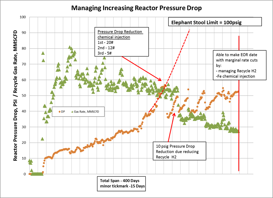
For example in a Naphtha Hydrotreater, both recycle H2 and Fe Injection agglomerant chemistry was used to extend cycle length. Compressor spillback was used to reduce hydrogen forward flow (caution need to ensure compressor stays away from surge).
ERIC LIN (Norton Engineering Consultants, Inc.)
High pressure drop in bed 1 is normally caused by contaminants in the feed that may not be picked up by the feed filters due to insufficient specification. Whereas most hydrotreaters can get by with simple cartridge filters, hydrocrackers can generally benefit from an automatic backwash-type feed filter. These filters generally use either UCO or filtered feed as a backwash medium and the process is automated by a high pressure drop setpoint.
If the high pressure drop were to occur beyond bed 1, then the ratio of graded catalyst in each bed should be calculated. If the ratio is greater than 2.5:1 from one layer to the next (i.e. active catalyst to support catalyst or support to larger support), then there exists the possibility that catalyst is migrating from bed to bed. If the ratio is fine, then the reactor internals, specifically the redistributors after quenches, require attention. The Licensor would have designed the reactor internals to accomplish a preferred flow regime and to minimize the pressure drop between beds. As most reactor internals are proprietary, a consultation with the Licensor is typically required.
VERNON MALLET (Honeywell UOP)
Methods of mitigating bed 1 and lower beds pressure drop can best be described as a process of identification of those factors either collectively or individually contributing to the pressure drop issue. Generally, bed 1 pressure drop escalation can be identified as feed processing (which may include feed types, feed contaminants and amount and type of contaminant), mechanical related or catalyst related. Pressure drop issues related to lower beds are much more difficult to identify and therefore during operation it is difficult to lessen or mitigate the impact.
Bed 1 pressure drop issues related to feed processing can be lessened or mitigated by first identifying the root cause upstream of the hydroprocessing unit. Identification of contaminants requires extensive lab analysis of the various feeds that hydroprocessing units process in the cycle due to continuous changes in refinery crude slates or changes in upstream feed processing unit operations that provide varying feeds to the hydroprocessing unit. Identification of feed contaminants and monitoring changes to the upstream unit operations during the cycle may indicate opportunities for adjustments that lessen the impact of increasing pressure drop to allow the cycle to continue. Identification of feed contaminants will also provide valuable detailed information of various contaminant levels so that a robust graded bed system can be provided for bed 1 either during the cycle via a mid-cycle skim or developed for subsequent cycles. Upstream processing units providing various feed sources to hydroprocessing units may also experience higher than normal corrosion which would result in increased amounts of iron or other corrosion products that would impact bed 1 and possibly lower catalyst bed pressure drop.
Identification of particular refinery crudes that result in feeds with higher than design levels of contaminants (metals, asphaltene, and carbon residue) should be undertaken to determine root cause of pressure drop. Feed types that are more reactive resulting in polymerization and condensation to occur may also be contributing factors. Identifying particular crudes as contributors and processing these would then need to be economically evaluated against removing these crudes or conducting a mid-cycle skim or continuing the cycle at reduced feed rates to achieve the desired cycle and turnaround timeframe. Reduction in recycle gas rate will also lower apparent bed pressure drop, although a large move may accelerate rate of coking reactions.
There are chemical additives designed to reduce top bed pressure drop which in some cases have demonstrated a degree of success. A better approach is to implement a guard bed strategy which will help manage unforeseen causes of top bed pressure drop.
Identifying the cause and mitigating the impact of increasing pressure drop in lower catalyst beds of a hydroprocessing reactor is more difficult during the cycle. However, there are possible scenarios that can contribute to increasing pressure drop in the lower beds. Generally, catalyst fines are swept from the catalyst beds and removed from the reactor by the liquid and gas. This is also true for small micron size particulates such as iron sulfide. Inertia is the driving force for this particulate removal. However, what can occur is the driving force or inertia starts decreasing as the rate of vaporization increases down the reactor resulting in these smaller particulates depositing in the quench zones or lower catalyst beds. Operating with highly reactive feeds that have a higher amount of coke precursors condensing to form coke, operating at low hydrogen partial pressure in lower beds and asphaltene precipitation are also possible causes of bed pressure drop increase in the lower beds.
SERGIO ROBLEDO (Haldor Topsoe, Inc.)
The methods available to mitigate pressure drop are dependent on what the cause of said pressure drop is. Generally speaking, lowering treat gas rate will lower the pressure drop through a catalyst bed. This will of course, not reverse/correct the pressure drop but will only buy the refiner time to plan a catalyst skim or replacement. Lowering feed rate will also reduce the pressure drop, but that is usually not an attractive option due to the economic implications.
Depending on the feed type, and operating conditions, another option would be to lower the feed temperature to bed 1. This will reduce the amount of feed that vaporizes, which will directionally lower pressure drop in the bed; however, this lower reaction rate will have to be compensated in downstream beds which will lead to uneven catalyst deactivation rates.
Iron Particulates
One of the major culprits of pressure drop build-up is particulate solids that enter with the feed. As mentioned in question 21, engineering the addition of a feed filter, if one is not already present, can dramatically impact the pressure drop build profile. Despite crude desalting and feed filtration, solids may still be present in the feed. If a filter is already in place, the plant personnel should investigate changing the micron size of the filter element. It is important to keep in mind that these elements are sized either as nominal or absolute basis. An absolute size filter will not allow anything above the micron size it is rated for to pass through, whereas a nominal filter will include an efficiency rating or degree of filtration. An absolute size filter essentially has 100% efficiency in preventing particles larger than its rated size micron. Usually, a change from nominal to absolute will improve the build profile during the cycle. The material of the filter element could also be changed, but the refiner should check with their filter supplier for the appropriate solution. However, these changes may require more frequent element change-outs and/or backwash frequency. The refiner will have to decide what is feasible from a maintenance schedule standpoint when changing to a smaller size micron filter, or filter type.
Some of the frequently encountered bad actors are:
• Corrosion products (iron scale and debris)
• Catalyst fines or dust
• Coke fines
• Sediments
• Salts (Na, K, etc.)
• Large carbonaceous scale spalled from the furnace or heat exchangers
If pressure drop is a result of iron particulates, there are chemical additives that can be injected with the feed to agglomerate the iron in the catalyst bed. This will open pathways for the liquid/gas to flow through and lower the pressure drop across the bed. Typically, this has diminishing returns during each subsequent dosing. This method is also a means to extend cycle length to allow the refiner to plan a catalyst skim/change-out and will not completely solve the pressure drop issue. Check with your chemical supplier for appropriate chemical in their respective portfolio.
Carbon Accumulation
Pressure drop arising from carbonaceous accumulations in the catalyst bed may be reduced by applying a ‘Hot Hydrogen Strip’ and/or a ‘LCO Flush’. Haldor Topsoe can furnish both procedures. Alternatively, depending on the nature of the issue, certain commercial additives may be added to the feed that are intended to reduce fouling and/or pressure drop caused by carbonaceous based foulants. As before, check with your chemical supplier for the appropriate antifoulant technology.
Ensuring that the hydrogen partial pressure is maintained at recommended levels throughout the reactor will mitigate pressure drop due to exponential coke formation.
Lower Bed dP
There are a few potential causes of lower bed dP. One such cause is the presence of colloidal clays in bitumen-derived feeds being processed in gas oil hydrotreaters. These very small particles become suspended in the oil and get through filters and/or graded beds. As the temperature increases, as is the case in the lower beds of a reactor, the colloidal clays precipitate out after a certain amount of hydrotreating of the feed has taken place resulting in pressure drop issues in the lower beds. In these situations, the use of a larger size catalyst in the lower beds of a reactor will extend cycle length before pressure drop becomes an issue.
A second and more common reason for pressure drop in lower beds of HT and HCU reactors is low hydrogen partial pressure and low hydrogen availability in the bottom beds. As the temperature rises over the course of the run, hydrocracking reactions increase. If the hydrogen availability, and in turn hydrogen partial pressure is not kept at sufficient levels, carbon formation may occur, resulting in pressure drop issues in the bottoms beds.
Another cause could be if liquid quench is used. This liquid may contain particulate matter, such as iron sulfide. Just as it would cause pressure drop in the top bed, this particulate material would cause pressure drop in the bottom beds. If a filter is not already present on this stream, one should be engineered for it. Also, the use of a graded bed in future loads would be prudent.
Mitigation Steps
The approach in mitigating pressure drop would not be much different if said pressure drop developed in a lower / lag bed in the catalyst system. Lowering treat gas rate and feed rate to the problem bed would still apply, as well as, changing the temperature profile and performing a hot hydrogen sweep and/or LCO flush. Running close to the unit dP limit (dictated by either outlet collector or bed support design) will also help extend cycle length.
The refiner may also need to check, if there was a change in feed composition, that could result in feed incompatibility causing the increased pressure drop. Asphaltenes may drop out and create a large amount of coke, sludge and/or change the viscosity of the oil. Typically, a change back to the typical feed will eliminate the issue.
Other successful solutions employed to mitigate pressure drop buildup from one cycle to the next are:
• Single-phase (gas) flow scale catcher (naphtha/kero service).
• Two-phase scale catcher (diesel and heavier).
o This includes a single stage filtration tray, for larger particles, and a dual-stage filtration tray, which Topsoe calls the HELPsc™(High Efficiency Low Pressure) scale catcher.
• Improved graded bed scheme.
o Expanding the volume of the grading system will directionally improve on-stream time. However, this may not always extend the cycle length proportionally for several reasons.
o Thorough understanding of pressure drop formation mechanism is important to engineer a solution that addresses the underlying cause.
• An example where expanding the volume may fall short is with NHT units experiencing dry point in the furnace and/or which process cracked naphthas.
o One remedy is monitoring the dry point and operating the unit such that the dry point occurs in the upstream exchangers.
o Cracked naphtha challenges have been addressed in Question 21, namely nitrogen blanketing tanks and/or running the stream hot to the unit.
• Changing installed catalyst size and shape, or sock-loading a bed that is dense loaded, will also improve SOR pressure drop and may allow for longer cycle lengths.
Please also refer to Questions 27 & 28 from the 2016 Q&A and Technology Forum for further details.