
Question 4: Does your refinery/company adopt a time-based rather than inspection-based replacement strategy for FCC reactor and regenerator hardware such as feed nozzles, air distributor, cyclones, cyclone support systems, and flue gas expansion joint bellows? If so, what is the planned service life for this equipment?
THOMPSON (Chevron)
It depends. I had to throw that in there. FCC folks always say that. Service life of each component is highly dependent on the application and varies from unit to unit. We have generally found that inspection-based replacement frequency is used as opposed to time-based. We use the results of the last unit inspection, coupled with a run history, to determine whether we need to replace a particular component.
Unit monitoring is extremely important and we do not want any surprises when we open up the unit. As an example, we would try to use cyclone erosion predictions to determine whether we are going to have an issue with cyclone wear when they get inside. We have adopted an upgrade strategy for high-wear, low-reliability components. We generally plan for at least a five-year run. And if we have components that will not make that run, then we try to address those selectively. We have developed Best Practices for most of those components.
Our expectations for typical service life of some of these components would be feed nozzles—five to 10 years; air distributor—15 to 20 years; reactor and regenerator cyclones—15 to 20 years; cyclone support systems—15 to 20 years; and, flue gas expansion bellows—15 to 20 years. Again, this service life is highly dependent on the severity of the unit and the particular configuration.
Obviously, operating conditions and run history have a big effect on the service life. The other thing that we found that is a big impact is the number of shutdowns. If you have a lot of emergency shutdowns or the unit is unstable a lot of the time, that is going to greatly affect the service life.
WARDINSKY (ConocoPhillips)
We use a combination of inspection-based and time-based replacement schedules for converter section internals; for example, feed nozzles, depending on the particular licenser nozzles used. It is not uncommon to replace feed nozzle tips on each turnaround. We generally recommend that everyone have a spare set of nozzle tips or nozzles around ready for replacement on turnaround.
We would typically start looking at replacing regenerator internals, such as cyclone systems and air distributors, after 15 to 20 years of service or if significant sigma phase embrittlement is evident from metallurgical analysis. Reactor disengager and cyclone systems can last longer—25 years or so is not uncommon—before metallurgical changes, such as carbide formation, start to limit welding repairs. This assumes that these equipment items are not replaced sooner during capacity expansions. Flue gas expansion joint bellows replacement is completely based on inspection criteria, except for bellows upstream of flue gas expanders, which typically are replaced every turnaround.
ASDOURIAN (Sunoco Inc.)
Sunoco relies on an inspection-based replacement strategy. The inspection-based strategy for the listed items will vary by component. Many factors come into play when making these determinations. Note that the inspection for all but one of the components—that being the flue gas expansion joint bellows—must be done when the unit is down. And even on the bellows, a complete visual inspection cannot be performed on the expansion unit when the unit is running. Therefore, these two must be looked at when the unit is down.
The inspections are performed using guidance and knowledge provided by these documents: API-RP571—Damage Mechanisms Affecting Fixed Equipment, API-RP579— Fitness for Service, and API-RP936—Inspection and Testing Monolithic Refractory Linings and Materials. These are the documents our Inspection and Reliability folks utilize.
The listed components, and others, are subjected to a document review as early as 24 months prior to the turnaround. The historical inspection records are reviewed by the team and a determination is made of the likely condition of the components. These are reviewed by the business team during the Turnaround Preparation meetings. An inspection work scope is then generated and assigned to each of the components. Upon gaining access to the equipment, a condition assessment occurs utilizing all of the documents. The conditions are noted in the inspection report and items that revealed excess wear and damage will be noted in recommendations for future repair or replacement.
JIM WEITH (Mustang Engineering)
One thing I did not hear addressed was the flue gas piping, as I said I worked on some time ago. We learned from the metallurgical folks—who can explain this better—that apparently things migrate in stainless piping. This was a hot-wall pipe. After 12 to 14 years, it starts cracking. We did have that experience. Every time we had a thermal cycle, we would come up and find a crack in our flue gas piping. Then, we would have to schedule in time to get that fixed. And of course, it was always at some out-of-the-way place that was nearly impossible to get to. So ultimately, we bit the bullet and replaced the flue gas piping in its entirety.
WALKER (UOP)
I agree with that. What we do is with the entire flue gas is cold-wall for a new unit. That includes the line, the orifice chamber, and the slide valve.
WARDINSKY (ConocoPhillips)
The only place nowadays where you expect to see a hot-wall system would be upstream of the expander and those areas do require special attention from the mechanical folks to make sure the metallurgy that exists there is still in good shape.
Submitter
Question 5: What is the shortest possible time between oil out and entry for maintenance on large inventory, high capacity FCC units? How is this achieved?
HOWELL (Holly Refining)
With FCCs at 27,000 bpd and 9,000 bpd capacity, neither of our units really qualifies for high throughput or large capacity. However, in discussions amongst the members of the panel, we found that throughput and inventory are not necessarily good indicators of how quickly you can move oil-out to maintenance-in.
Historically, Holly has obtained our first entry permits for vessels in the FCC complex 36 to 48 hours from oil-out. During a recent unplanned outage in one of our units, we were still able to open the external manways within 48 hours of oil-out. We were able to do a visual inspection, which was our first-entry in the complex, about 24 hours later at 72 hours from oil-out. We were unable to enter the reactor for three more days, however, mostly due to coke buildup in the reactor vessel. In fact, we were not able to steam because of the circumstances of the shutdown.
With our infrequent FCC shutdowns, we found that the best method for getting into the vessels rapidly is using a set of Evergreen procedures. The latest version of those procedures is stored electronically on the company Internet. Several days prior to any shutdown, operators conduct a Safety Task Review with the engineers, Operations management, and shift supervisors. The procedure is read through with a critical eye. We make any changes necessary at that time. As the unit is shut down, procedures are checked off and annotated so that after the shutdown, we can go back and incorporate those into the most current, correct version of those procedures.
WARDINSKY (ConocoPhillips)
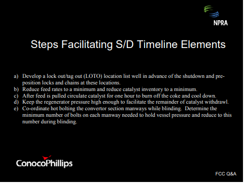
ConocoPhillips operates four FCCs with more than 450 tons inventory. The largest in our system is 650 tons. Three of these run more than 80,000 bpd throughput. The shortest period between oil-out and regenerator maintenance that we have been able to achieve is 48 hours. Getting into position to isolate the converter section from the main fractionator is a first key step. There are several steps that can facilitate the shutdown time elements, as shown on the list. First, you want to make sure you have a lock-out/tag out location list and plot limit blind list well in advance of the shutdown. Assign teams to go out and get those blinds in and positions tagged out. Reduce feed rates to a minimum. Reduce catalyst inventory to a minimum. Circulate catalysts just long enough to burn off the coke and cool it down. Again, one of the main factors in gaining access is getting catalyst out. Keep the regenerator pressure high enough to facilitate catalyst withdrawal. You might want to look at supplemental compressors for that. And then, get your boiler makers working on the manways, hot bolting them as you are blinding.
THOMPSON (Chevron)
FCC shutdown timing is set by requirements to isolate the equipment and remove the catalyst and oil. We have considered three days as pacesetter. Unfortunately, our larger units tend to be a little longer than that. We find that the roadblocks to rapid entry are typically catalyst withdrawal and isolation. That includes reaction mix blind installation.
To speed the catalyst withdrawal, we have gone to either multiple withdrawal points or we use of external catalyst coolers to basically allow us to withdraw catalysts at accelerated rates. As far as getting the reaction mix blind in, we have a couple of units that have the Zimmermann and Jansen mix valves that allow us to isolate the fractionator from the reactor. However, you still have to put a blind in because those systems will not allow you to get entry with just the closed valves.
ASDOURIAN (Sunoco Inc.)
Sunoco successfully opened the doors for entry into the reactor regenerator on one occasion within 30 hours of pulling feed on an FCCU. This particular unit has a 750-ton inventory and runs in excess of 80,000 bpd. However again, this was just one occasion. Typical for us is 48 to 60 hours. The timing associating with catalyst de-inventorying is probably the single greatest contributor to being able to expeditiously gain access. Other factors contributing to expediting the process are dumping catalyst via multiple nozzles and the experience level of the Operations staff that are on duty at the time when this is occurring.
KEVIN PROOPS (Solomon Associates)
We do not have data on the oil-out/oil-in or oil-out to mechanical entry, but we do have data available for what is Best Practice on FCC turnaround duration overall. This data is from 278 FCC turnarounds between 2000 and 2006. Out of those 278, we have seen 10 or 12 units of all scale—from less than 25,000 bpd to well over 100,000 bpd —that define Best Practice. This is a line that is defined as three times the unit capacity of 1,000 bpd plus 290, which gives you hours of downtime; so again, three times capacity plus 290. What that equates to is for a 50,000 bpd unit, you are looking at about 18 days of downtime. For a 100,000 bpd unit, it is about 25 days of downtime. So clearly, we do see scale effects on this. Since we have many clients that have small refineries and small units that worry that they cannot achieve the same performance as big refiners do, I would like to reinforce that there are some things smaller refineries and smaller units do seem to do better. One of them is shorter FCC turnarounds.
MATT BAILEY (Valero Energy)
I have a question on resid crackers. Are people seeing more issues with high CO levels in the reactors upon initial manway openings and what are people doing if this is encountered?
WALKER (UOP)
CO is a combustion flue gas. That should all be gone early in the shutdown. Am I missing something here?
MATT BAILEY (Valero Energy)
Yes. We have had this experience and I have talked about it with some other folks in the industry. On initial breaks on the reactor, you go to sniff that reactor at that manway. And despite having a good ventilation on the reactor, if there is a lot of coke inside the reactor due to either a breach in the riser termination device or some other mechanical failure that is occurred, there is a lot of coke contained inside that reactor, There is actually some smoldering that goes on inside that reactor as a result of maybe not cooling down the reactor during the decommissioning step. I am just wondering if anyone else has had that experience.
WALKER (UOP)
I understand the question now. We are talking about on the reactor side. Yes, I have heard of this scenario and yes, you do have to be very careful, particularly with resid units or other units that have a history of building up coke in the reactor. You do need to be cognizant of this when you first break open the manways. You also need to be ready to snuff that out with steam or close the manways back up again until you can get further cooling.
THOMPSON (Chevron)
I want to add that it can also be a problem on the regenerator side if you shut down in an emergency basis and have unregenerated catalyst in the regenerator. You can generate a high CO environment. And when you open the manway, if the catalyst is hot, you could get a detonation. That is something to check very carefully before you fully open things and enter.
JIM WEITH (Mustang Engineering)
I have two comments. Many, many years ago, we had a 5,000 bpd FCC with maybe 40- ton inventory. We have a novel feed nozzle arrangement—Ventory-type—that our licensor had provided for us and it plugged off about every six weeks. So for about the first six months until we replaced those, we were shutting down every six weeks to pull those nozzles out and clean them. We got pretty adept at that although we did not have to enter the reactor. All we had to do was de-inventory the regenerator. So it was: shutdown, cool down, de-inventory, pull the nozzles, clean them, put them back in, re-inventory, and up again. Feed-out to feed-in was typically 36 hours, as I recall. We got pretty adept at it after the third or fourth time. That was a genesis of an article written in the Oil & Gas Journal some time ago about using diagrams for unit startups, which can be applied to shutdowns as well.
The second example occurred at a Los Angeles refinery. You might anticipate that people were reluctant to have any emissions so they felt they always had to shut the air blower down before the catalyst extend pipes lost their seals. This resulted in a lot of catalyst being left behind in the regenerator. Then, you had to open up and vacuum out, which took a couple days because it was hot. Generally, we had one or two personnel burn incidences each time that happened. This could have easily been rectified by at least putting trickle valves or some sort of a heel device on the secondary cyclones, if not both sets of cyclones so they could run the air blower longer.
PHILLIP NICCUM (KBR)
This is a question for Ralph Thompson or anyone else who would care to answer. For units that have a valve between the reactor and the main fractionator, have there been issues with an inability to close that valve after it has been in service for a while, perhaps, due to coking somewhere in the system?
THOMPSON (Chevron)
I am not aware of the valve coking up to the point where it could not be closed. However, I think that is a potential concern because if you have a long run, you have a lot of coking. And of course, there is a point where you could have heat loss. At least, there is a potential for some coking there. I must admit that we do not have enough run experience on those systems to be able to answer that question one way or another. Certainly, I mentioned that you really do need to be able to install a blind, in addition to the valve, so that is another consideration in that installation.
WARDINSKY (ConocoPhillips)
Phil, I assume you are talking about the multiple-use, isolation blind device valve? Then yes, we have several of those in our system. Thus far, I think we are about two or three years into a run using one of them on one unit and it has worked fine. It has not failed.
WALKER (UOP)
The traditional gate valve-type: You could ask the audience here, but I know a number of people who have had trouble shutting those at the end of the run due to coke formation. You clear the coke out and you can use it during the startup, but problems closing them are not uncommon.
ASHOK MATHUR (KBR Solutions)
I just want to warn against storing procedures only on the Internet. I have two procedure manuals myself. We had a shutdown during complete power failure. Not even the PC was working so I was very happy that one guy had a hard copy in a drawer. Also, your IP friends can let you down when your server is down. And when you are starting up, you have no access to anything. So I really would like to make a plea: Keep a hard copy of your procedures somewhere in a drawer, even if your Quality people do not like it.
BOB LUDOLPH (Sunoco Inc.)
I would like to address Phil Niccum’s question regarding the history of closing these valves and whether it has been a problem. We have one location that had a Zimmermann and Jansen installation. I am aware of one occasion where we had difficulty closing that. We eventually did. I cannot stress enough the maintenance of these valves. When you come down for a turnaround, pack and seal them properly. Go through all the proper procedures and they will be reliable for you. Also, the hydraulic gun that is used for sealing it is a very valuable piece of equipment. There is not really a substitute that you could find in a refinery for one of these devices, so protect it that it does not get misplaced.
SHELLY ROMMELMAN (Washington Group International)
To piggyback off the gentleman’s question regarding coke formation in the dilute phase of the reactor: Say your refiner has a few close-couple cyclones and they choose to reduce our water-make by turning off their dome steam. Do you guys have any recommendations to minimize coke formation for startup or shutdown?
WARDINSKY (ConocoPhillips)
If you are not using dome steam on a close-coupled cyclone system, you are probably going to be looking at a lot of coke in the reactor. So the first thing I would say from a maintenance standpoint is prepare to get in there with a crew of people with jackhammers to go at it. It is probably going to add some turnaround time. We have had some failures of closecoupled systems in the crossover ducts where we have not seen any indication of that, in terms of a yield shift. But when you went in on turnaround, there was coke the size of a Volkswagen up in the reactor. I think that is how they phrased it. They got to the point where they were looking at having to dynamite it out. I do not think we got that far along. I think we started using some jackhammers and got it out. It will delay your turnaround time because if you are doing any work lower down in the reactor or the stripper vessel, it is going to have to wait until you get all that coke out of there.
WARREN LETZCH (Shaw, Stone & Webster)
I would have to say the same thing. I think you would be much more advised to try to reduce the stripping steam or something else if you felt you had a sour water problem and address that issue. I would not have thought that the amount of dome steam you were putting in was all that significant compared to, say, the dispersion and stripping stream that you put through the unit. In my opinion, the coking issue in the top of a reactor like that is such a safety issue that I do not really understand why anyone would even consider doing that, based on the talk we had this morning.
WALKER (UOP)
You could probably get away with less dome steam if you had very clean feed than if you had heavier feed there. My observation is that there is a pretty strong correlation there.
Submitter
Process
Question 6: Some CO and waste heat boilers operate with bypass stacks separated by seal pots or isolation valves. Maintenance of these seal systems can be expensive and these seal systems can be sources of poor reliability. What design upgrades and operating practices have enabled you to eliminate these bypass systems?
HOWELL (Holly Refining)
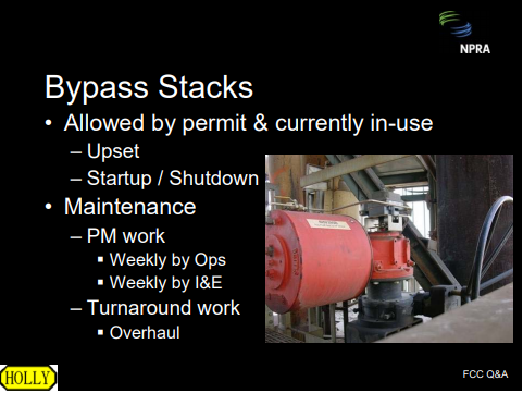
Holly Refining continues to use bypass stacks with diversion valves at both of our refineries. Those stacks and diversion valves are allowed by permit and we use them during startup/shutdown manning upset conditions. Both our Operations and Maintenance groups are assigned weekly preventative maintenance tasks to ensure operability when we do have to throw these valves. Those preventative maintenance tasks include weekly partial exercise in both the valve and the positioner. During scheduled turnarounds, valves are disassembled, inspected, and often reworked. Because we have CO boilers in both locations, we do not foresee any major design changes to these systems. Certainly at this time, we do not see any need that we might end up removing the diversion valves from our systems.
WARDINSKY (ConocoPhillips)
Flue gas heat removal equipment in FCC service has been a major source of unplanned feed outages and maintenance work. Elimination of bypass ducting around this type of equipment necessitates improved reliability off the heat removal equipment.
Steps to improve the reliability of the CO boiler and waste-heat boiler systems include those described below. I want to emphasize that if your boiler feed water is coming from another part of the plant, such as the Utility part, do not ignore it. You really need to have your unit engineers on the FCC pay attention to boiler feed water chemistry because in some cases, that chemistry has lead to failures in this type of equipment. We have also experienced failures in this equipment due to poor design of the intermittent blowdown (IBD) systems with deposits of sludge and solids inside the tubes. Obviously, make sure that you are putting enough boiler feed water to the tubes. We do not want to dry them out because that will cause them to fail. This equipment is typically hard to inspect and we do not do a good job on most turnarounds, in my opinion, of inspecting this kind of equipment. Obviously if you have had repeated failures of this equipment during a run that are not process related, then I would suggest that you look at replacing equipment with a better design.
THOMPSON (Chevron)
We would agree that CO boiler reliability has generally been poor and often does not meet the run-length requirements. This necessitates the coupling of the CO boiler from the flue gas train. Generally, we prefer to take one of two approaches. The first approach, which is preferred, is to change the operation so we operate in complete CO combustion. Often, that requires regenerator modifications. It will also necessitate increased oxygen demand and might require supplemental air or oxygen. It does have benefits in improved regeneration, high cat activity, and improved yields. Unfortunately, there are times when that is not possible, such as when you are feeding resid. We operate several units of the SSW R2R design that have twostage regeneration and those have a first-stage system that separates combusts the CO. The heat removal is non-fired and has been very reliable. The CO incinerator does have a bypass system, but we have not had to use it.
WALKER (UOP)
A field boiler is generally less reliable than most of the FCC equipment. For a grassroots unit, we would try to design for a complete combustion, if at all possible, in order to eliminate a CO boiler. For high resid feedstocks, we would use catalyst cooling to the maximum extent. We would then use partial combustion for very high resid feedstocks. We recommend complete combustion with the cat cooler for feedstocks having up to around 3% or 5% concarbon, depending on the refiner’s comfort level and partial combustion being on that level. If partial combustion is justified and a CO boiler is installed, we would recommend a bypass stack with a diverter valve.
PHIL NICCUM (KBR)
Operating in a partial combustion does offer advantages for catalyst activity maintenance for heavy feedstocks, particularly those with a lot of vanadium. On several occasions, we would design units that could be operated either in complete CO combustion or partial CO combustion and allow the refiners to change the operation as their feedstock or other requirements change.
Submitter
Process
Toledo Rally Spotlights RFS Threat to Refineries
Video Media
RFS: Fix the Mess
Video Media
AFPM Pres. and CEO Testifies on the RFS
Video Media


Question 7: Is your company either considering, or actually implementing, FCC projects that include reduced CO2 emissions (greenhouse gas reduction-GHGR) as an offset/credit?
WARDINSKY (ConocoPhillips)
We do not have any current FCC projects that plan on utilizing some form of CO2 offset or credit in the emissions analysis. ConocoPhillips has performed a limited modeling study to evaluate the effect of operational changes on CO2 emissions from the FCC. Also, the study indicated that there is very little you can do to reduce overall emissions without also overall significantly reducing unit throughput or conversion. One obvious adjustment is to increase feed preheat to reduce coke yield and get back conversion by increasing equilibrium catalyst activity. However, the increased CO2 emissions from the feed heater nearly offset the reduced CO2 emissions from the regenerator flue gas stack. FCC energy efficiency improvement projects that we have been implementing recently within ConocoPhillips include replacement of steam turbines with electric motors and optimization of feed preheat furnaces. Other opportunities to improve FCC energy efficiency include recommissioning out-of-service flue gas expanders and increasing heat integration between the main fractionator and gas plant reboilers.
As an informational note: In the 1980s, Air Products reported on an FCC process utilizing O2 enrichment for coke combustion with CO2 recycle and sequestration. This process presents several technical and economic challenges to FCC operations.
HEATER (BASF Catalysts)
As Mike mentioned, it is important to remember that the FCC runs in heat balance. All the heat needed to run the process will eventually come out as CO2 either in the flue gas, the CO boiler or the feed heater. Two main sources of CO2 generation are from the combustion of coke and from the CO boiler/feed preheater stack gas. Optimum design of the CO boiler and feed heater burners can mitigate CO2 production. CO2 from the flue gas, when looked at in the big picture, is very minor compared to the CO2 generated from the fuel produced by the FCC; for example, gasoline and diesel fuel. When in petrochemical mode (C3s and C4s are going to petrochemical market), that CO is reduced. Likewise, when slurry goes to carbon black, that CO2 is reduced.
Process