


Question 24: What is your engineering design practice for selecting metallurgy for hydroprocessing unit’s amine systems? How does chloride level impact the metallurgy selection?
JOE RYDBERG (CITGO)
At CITGO Lemont Refinery, the base practice is to install post weld heat treated carbon steel piping for the main run of the pipe upon initial fabrication. For a set length downstream of control valves, 304 stainless steel is installed to try and mitigate the corrosive effects of flashing across the valve. However, in recent years, there has been a notable increase in the amount of corrosion that has been observed on the carbon steel lines. In areas that have been found to be corroding rapidly, an installation of 304 stainless steel has been put in place of the carbon steel. The concern of chloride content and its cracking potential in the circulating stream has been weighed against the risk of carbon steel corrosion. Thus far, the very localized corrosion of carbon steel and its difficulty of detection by common NDE methods has been deemed riskier than chloride cracking concerns, and the installation of 304 stainless steel has taken place.
The reason for choosing 304 stainless steel over 316 stainless steel is the damage that has been observed is mostly localized corrosion at heat affected zones (welds). While 316 is generally better for pitting resistance in aqueous systems, the benefits it has over 304 in a general wall loss scenario are not significant enough to warrant the additional cost. We have found 304 stainless steel to be adequate in resisting corrosion (as we have a long history of its use just downstream of control valves in this very environment) to an acceptable degree. That is the primary driver behind the choice to use 304 stainless steel.
JIM JENKINS (Shell Global Solutions)
For “normal” amine service, carbon steel (CS) is the material of choice. However, hydrotreater applications that operate at higher pressure will have higher acid gas pick up in the amine. This causes higher temperatures in the contactor. For applications where temperatures exceed about 90⁰C (194⁰F), austenitic stainless steel (SS) is normally selected for the bottom 1/3 or ½ of the tower.
When chlorides are present, SS can experience chloride-induced stress corrosion cracking (CSCC) at temperatures above 60⁰C (150⁰F). Alternate materials not subject to CSCC include alloy 825, alloy 625 and alloy 2205 (duplex).
The industry generally limits the amount of chlorides in the circulating amine system. When high pressure hydroprocessing units require SS contactors, the chloride content of the amine is generally limited to 250 ppm (maximum).
In summary, recommended materials of construction for amine systems that contain chlorides:
|
Service |
MOC |
|
Lean Amine |
CS |
|
Rich Amine < 90 oC |
CS |
|
Rich Amine > 90 oC |
Alloy 825, alloy 625 and alloy 2205 (Duplex) |
CHRIS WOZINAK (Honeywell UOP)
Historically, UOP has designed Amine Scrubbers with Killed Carbon Steel that is post weld heat treated (PWHT) and has additional corrosion allowance. Due to the corrosive nature of the rich amine, the trays are upgraded to 304SS and the mesh blanket is typically 316SS. While most customers have seen success with this design, even with feed sulfur levels exceeding 3%, there are some who have seen accelerated corrosion on the wall opposite the rich gas inlet line. Typically this location will receive weld buildup, followed by application of stainless steel patch plates or weld overlay, followed by PWHT. If the unit contains chlorides, UOP is concerned about the potential for chloride stress corrosion cracking (Cl-SCC) of any austenitic stainless steels (300 series) and so we will upgrade the 304SS and 316SS to Alloy 400 (also known as Monel), which has good resistance to chlorides and H2S at moderate levels.
Year
2019
Submitter
Process
Question 25: What are your key factors around amine contactor operation in hydrotreating units?
JOE RYDBERG (CITGO)
The biggest key factor in amine contactor operation in hydroprocessing units is controlling the lean amine flow and the lean and rich amine loading. We have seen corrosion in rich amine piping likely due to elevated H2S loadings and higher velocities (both lean and rich), especially when unit rates are changed quickly.
Adjust amine circulation to maintain desired rich amine loading (Typically 0.3-0.45 mol total acid gas / mol of amine loading). Ensure sufficient amine by:
o Sampling rich amine and determining H2S loading for optimization (reduce amine circulation)
o Controlling lean amine flow based on temperature rise of amine coming in or out of contactor (relatively new )
o Set minimum amine circulation based on maximum H2S recycle content
o When pushing unit rates, amine loading, fluctuations in pressures and flows can “overwhelm” the amine and H2S can breakthrough.
o Develop calculation tools to estimate sulfur load and set lean flow rates accordingly.
Adjust amine regenerator to maintain desired lean amine loading to meet FG H2S specifications.
There have been upsets in the sulfur unit due to hydrocarbon carryover into the amine. Typically this is caused by large hydrocarbon carryover events (Loss of HPS levels, upstream Hydrocarbon fractionators). Hydrocarbons cause foaming, solids will contribute to that as well. The amine system has to be kept clean (filtered).
• Amine temperature typically controlled to 120-130F for H2S control (less critical for MDEA based systems)
• Properly designed wash water trays designed and installed to minimize entrainment / carryover of amine into recycle gas compressor (4 trays, with a water circulation to provide adequate tray loading)
• Process inlet temp should be maintained 10 degF above amine temp for vapor hydrocarbon systems to prevent condensing
o Less of a risk of condensing Hydrocarbons in Recycle H2 amine contactors
ROBERT STEINBERG (Motiva Enterprises)
Amine absorbers that remove H2S from a gas phase stream need to be operated with the proper amount of amine, at the right temperature and without liquid hydrocarbons.
Amine rates need to be high enough to remove the H2S in the sour gas and to keep the H2S concentration in the rich amine low enough to avoid corrosion. In low pressure service, such as a stripper offgas going to fuel gas, only a limited amount of H2S can be captured by the amine and the amine rate needs to be adjusted to control the H2S content of the sweet gas.
In a higher pressure contactor, such as in the recycle gas loop of most hydrotreaters, high concentrations of H2S can be captured by the amine. Allowing the rich amine to be saturated with H2S in a Recycle Gas Scrubber would lead to excess corrosion in carbon steel lines and equipment. Normally, the amine rate has to be adjusted to maintain the H2S loading in the rich amine within acceptable limits. Typically, at these amine rates there is minimal H2S remaining in the sweet gas and changes in the amine rate have negligible impact on the remaining H2S in the sweet gas. The maximum H2S loading in rich amine is normally expressed in units of moles H2S per mole of amine, the maximum acceptable limit depends on the type of amine used.
Liquid hydrocarbons should be avoided in gas-phase amine contactors as they tend to cause foaming. Liquid hydrocarbons are prevented by:
• Avoid carryover of liquid hydrocarbons in the sour gas to the scrubber. This requires proper sizing of the upstream separation vessel like a Cold Separator with good internals. As a minimum there should be some sort of inlet device to help separate gas and liquid in the Cold Separator and a mesh pad below the vapor outlet nozzle. In some cases, particularly if the unit charge rate has been increased, more sophisticated devices like a cyclone separator in the Cold Separator are needed. If the Cold Separator is not large enough, an additional knockout vessel on the vapor line between the Cold Separator and the scrubber may be helpful, such a vessel normally has internal cyclones to remove liquid carried over from the Cold Separator.
• Keep the lean amine to the scrubber hotter than the sour gas to the scrubber to prevent condensation of hydrocarbons. A minimum 10°F margin is typically used but in some cases such as very high pressure units, margins of 20-30°F may be needed. It is often a good practice to provide a lean amine heater to heat the amine up to required temperatures as there may be limited ability to provide additional cooling of the sour gas in the upstream Reactor Effluent Air Condenser (REAC). A lean amine heater would generally be provided upstream of the Lean Amine Pump so it can be a low pressure exchanger. Low pressure steam is normally an adequate heating mechanism. Avoid using higher temperature heating sources that would result in high skin temperatures and potentially degrade the amine – limiting maximum skin temperatures to less than 260°F or simply keeping temperatures lower than in the Amine Regenerator Reboiler is a good practice.
• Provide facilities to skim hydrocarbons from the sump at the bottom of the scrubber. Even with good upstream separation and high lean amine temperatures, some hydrocarbons will often accumulate. These hydrocarbons are generally insoluble in aqueous solutions and form a separate liquid phase, since the hydrocarbons have a lower density than amine solutions they tend to accumulate on top of the rich amine. Level control devices using a dP transmitter will give a false low level if a significant hydrocarbon layer is present. Measuring the hydrocarbon layer can be difficult as the amount of hydrocarbons in an external level gauge will not be the same as in the tower. Using a gauge with a small level range by first lowering the level until it is drained and then raising the level to the middle of the gauge will give the same amount of hydrocarbon in the gauge as in the vessel, this information can be used to decide how much material to skim. Alternatively, an overflow device can be provided in the vessel sump at around the 50-60% level to continuously skim whatever liquid is at this elevation.
ALFREDO VILLA (Haldor Topsoe, Inc.)
Several operating conditions should be maintained and evaluated to determine the condition of the amine system. A properly operating amine contactor will yield a clean recycle hydrogen stream and minimize impact to downstream amine regeneration equipment.
Operating with a clean amine should mitigate potential foaming, corrosion, and heat stable salt build-up in the absorber system. Monitoring the concentration and circulation rate of the amine used is crucial to maintaining good operation in the absorber. These parameters will allow for adequate hydrogen sulfide absorption and maintain target recycle gas concentration. An adequate concentration of amine will reduce the potential of corrosion in the system by maintaining low rich amine loadings. A target amine strength will depend on the type of amine circulated and should be discussed with the amine vendor. Periodic visual inspection of the amine should be conducted to note changes in color and solids content. Typically, lean amine has a pale-yellow color and should be relatively free of solids, a change in color could indicate an increase in corrosion rates. For example, a change from pale-yellow to dark green could indicate a change in the iron sulfide content of the amine and an increased solids content. Solids in the system could lead to erosion of the iron sulfide scale protecting the inside of the piping. Removal of this scale exposes unprotected metal, which could lead to further corrosion. Along with the removal of the iron sulfide scale, solids in the system could stabilize foam.
Temperature control is of importance in any amine contactor system as it can lead to poor acid gas absorption. The loading capacity of the amine is directly impacted by the lean amine temperature, the cooler the lean amine the greater its H2S removal capacity. However, it is recommended that the lean amine temperature is maintained warmer than the gas feed. Lean amine temperatures which are too low, increase the potential for condensed hydrocarbons, which could lead to foaming in the contactor. Feed gas temperature control is also recommended as a high feed gas temperature leads to a higher lean amine temperature, which reduces the capacity of H2S removal.
GARY BOWERBANK (Shell Global Solutions)
Solvent hygiene is high on the list. Poor solvent quality, which is often measured in terms of high degradation products (Heat Stable Salts) or high suspended solids, can lead to both corrosion and fouling of the system but also increase the risk of foaming events. These foaming events are the most common issue to impact operations of any amine contactor, which can result in losses of solvent (if carried over beyond KO vessel) or off specification product. Sites may often focus on treating the symptom by dosing an anti-foaming agent, however we prefer to understand the root cause and tackle that. If not linked to solvent quality; then entrainment or condensation of hydrocarbons in the contactors is the most common root cause. So, having high efficiency gas/liquid separators upstream and maintaining lean solvent at least 5oC above the gas temperature are critical.
ERIC LIN (Norton Engineering Consultants, Inc.)
Other than the type of amine used, the most important operational factors for amine gas contactors are temperature and pressure drop. Lean amine coming to the column should be at least 10°F (6°C) hotter than the sour gas to prevent condensation of hydrocarbons and cause possible foaming. Sometimes a LP Steam heater may be necessary if the lean amine is too cold from the ARU. On the other hand, if the lean amine is too hot (~25°F greater than the sour gas), there exists the possibility of appreciable amounts of amine carryover into the sweet gas. Contactors should also have alarms indicating high pressure drop normally caused by foaming. Most contactors should have the capability of periodically skimming the oil from the top of the rich amine in order to proactively prevent this from happening.
PRASAD HARDIKAR (Honeywell UOP)
The primary purpose of an amine contactor /amine scrubber is to remove H2S from the circulating recycle gas stream or remove H2S from hydrotreating unit off gases before blending hydrogen rich gas with fuel gas.
Here are key factors to be considered in various stages:
Design/ Commissioning Stage:
• Remove oil or rust inhibitors present from construction
UOP always recommend degreasing of new/modified amine column with 2 wt% soda ash neutralization solution before putting it in service. Degreasing removes grease or protective oil layer on amine contactor /scrubber trays and internals which can contribute to foaming. Hydrocarbon layer is meant for protecting trays/internals from rusting during transportation and storage.
Operation:
• Limit hydrocarbons entering with recycle gas:
• Keep lean amine 3-5°C (5-9°F) warmer than inlet gas to prevent hydrocarbon condensation and consequent foaming
• Ensure mesh blanket in upstream knockout drum is working
• Lean and Rich amine loading:
Amine loading is expressed as mole loading of H2S per mole of Amine. Lean amine loading indicates efficiency of amine regeneration unit and capacity of lean amine to absorb H2S. Rich amine loading sets maximum H2S capacity for rich amine.
Higher rich amine loading increases potential for erosion in the rich amine lines due to two phase flow in the rich amine lines especially from downstream of rich amine control valve. This can have negative effect on the operation of the amine regeneration system as the lean amine will eventually become more contaminated with iron particles and have deficient performance. It is recommended to maintain rich amine loading < 0.4 mol acid gas/mol MDEA with KCS metallurgy lines.
It is quite tempting to reduce lean amine flow during operation from an optimization perspective. However, such reduction in flow with same acid gas (H2S) content increases rich amine concentration well beyond acceptable rich amine loading as amine will continue to absorb acid gas till saturation. Hence monitoring rich amine loading is a critical factor in amine contactor operation.
• Amine Appearance and Quality
Amine appearance and quality is one of the critical aspects to monitor.
It is observed that increase in total dissolved solids (TDS), total suspended solids (TSS), heat stable salts (HSS) enhances foaming tendency in lean amine. TSS are expected to be NIL and HSS at < 0.5% for lean amine solutions. These parameters are better controlled with mechanical filtration (with activated charcoal) and it may require replacement if foaming issue persists.
Lean amine displaying a green color is indicative of the presence of solubilized iron sulfides in the amine due to corrosion or issues with amine system filtering. Lean amine with a slight green color will continue to remove H2S from recycle gas adequately, but if soluble iron sulfide buildup in the amine is not eliminated, foaming could be a potential concern.
• Amine Color Guideline:
– Light straw = amine is in good condition
– Black or dark green = corrosion is taking place
– Light green rich amine = small particulates present
• Avoid excessive foaming inhibitor as this with increase foaming tendency
• As an operational task, regularly skim out hydrocarbon layer before it starts to build up
Year
2019
Submitter
Process
Question 26: What do you do to predict Silicon breakthrough in a naphtha hydrotreater? What are the consequences to the downstream units if breakthrough occurs?
AMIT KELKAR (Shell Catalysts & Technologies)
The primary source of Silicon is the anti-foam injection at the coker. Silicon is also present in a wide variety of crudes including Maya, Canadian syncrudes and Venezuelan. It may show up in straight run naphtha due to use of Silicon based additives in upstream crude production and pipeline operations.
One way to monitor breakthrough is to track cumulative Silicon content of feed compared to the design Silicon capacity of the installed catalyst system. This requires regular feed analysis. A reasonable estimation of feed silicon can be obtained by detailed spent catalyst analysis from prior cycles. Monitoring the progression of dT across the catalyst bed is a qualitative way to monitor Si breakthrough. The catalyst at the top of the reactor gets saturated with Si first resulting in shift of dT to the lower portion of the bed. This Si “wave” can be tracked by means of a plot of percent dT for each individual bed or even sections of the same bed provided adequate thermometry is available.
Another way to monitor Si is by means of a rigorous kinetic model while splits the catalyst bed into multiple “slices” and estimates an overall Si profile for different cycle lengths.
Si deposition preferentially poisons the HDN function of the NHT catalyst. In some cases, product nitrogen slip precedes Si slip. Nitrogen specification for reformer feed is 0.1 – 0.5 ppm. Increased N slip strips the chloride off the reforming catalyst and affects the metal / acid balance. It leads to fouling of recycle compressor blades, stabilizer trays, feed / effluent exchangers and overhead coolers due to deposition of ammonium chloride (NH4Cl).
High silicon (target < 0.1 ppm) in the reformer feed blocks the active sites and reduces regeneration efficiency by impacting Pt dispersion and Cl adsorption.
JOE RYDBERG (CITGO)
Silica capacity can become a run limiter especially on units that process Heavy Coker Naphtha. Typically the reactors in these units will contain a significant amount of high surface area Silica Guard catalyst in addition to the high active main bed catalyst. Silica is analyzed in the feed to ensure the unit is “on pace” with meeting its cycle length target. Silica pickup is temperature dependent. Work with your catalyst supplier to provide a total Silicon “trap capacity” number for the reactor and individually for the silica trap material, mainbed catalyst, and so on. At the end of the run, the Silica lab numbers are totalized and compared to the weight of Silica the spent catalyst “captured”. Each layer needs to be sampled and analyzed. Typically these compare pretty closely (10-20% or so). Need to make sure not to confuse Silica with Silicon. Work with your catalyst suppliers to potentially add additional Silica Guard catalyst and extend the next cycle. Tracking Silica can be an effective method to predict and schedule catalyst changes several years out. Looking at the Silica levels in catalyst samples at the bottom of the bed will also ensure that Silica hasn’t broke-through into the reformer. Typical consequences of Silica (which is a permanent poison) breaking through into the downstream reforming unit is loss of catalyst activity and yield
KA LOK (Honeywell UOP)
Regular monitoring of silicon levels in naphtha feed and reload of the hydrotreater catalyst as needed are tools to safe guard downstream catalytic units, primarily catalytic reformers. Generally silicon in naphtha hydrotreater feed is from byproducts of delayed coker antifoam. Analysis of the feed for silicon content should be on a composite sample collected over a coke drum cycle to determine a representative average concentration. Cumulative mass of silicon throughout the hydrotreater cycle can be tracked against the silicon capacity of the reactor catalyst inventory represented by the catalyst supplier. Although contaminant silicon will deposit in a relatively narrow band progressively through the reactor, a safety margin to account for catalyst bed bypassing and the length of the silicon removal zone should be included in estimating silicon breakthrough out of the hydrotreater. Periodic sampling of reactor effluent for silicon analysis near estimated end of run can be used to verify the estimate.
A hydrotreating process unit is commonly used to remove metals in the naphtha prior to feeding to a catalytic reforming unit, such as a UOP PlatformingTM unit. Reforming catalyst is very sensitive to silicon contamination. Silicon is an irreversible support poison. It reduces chloride retention and accelerates platinum agglomeration. At elevated levels this could lead to poor catalyst performance, increase in cracking, lower C5+ yield and lower activity. In addition, regular analysis of reforming catalyst for silicon concentration provides additional protection against poisoning.
SERGIO ROBLEDO (Haldor Topsoe, Inc.)
As stated in previous AFPM Q&A’s answer books (see 2014 and 2016), silicon will impact HDN activity to a greater extent than HDS (see Figure 1). Therefore, a good way to measure silicon pick-up is by tracking the feed and product nitrogen. The %HDN, and normalized WABT HDN, can then be calculated and the decline over time can be tracked.

Fig. 1 – Silicon impact on catalyst activity.
It is recommended that feed and product silicon be measured. This will allow the pounds of silicon being placed on the catalyst to be calculated and help determine when a Si breakthrough will occur. Alternatively, antifoam usage at the coker unit can be used to estimate pounds of silicon entering the naphtha unit. Check with your chemical supplier as to 1) how much pounds of silicon are present in each gallon of antifoam and 2) what percentage of that ends up in your naphtha cut, based on cutpoint.
Another important factor is to understand the silicon capacity of the installed catalyst system and its pick-up profile. A standard/max theoretical pick-up number should not be used to estimate breakthrough. Silicon capacity is dependent not only on the catalyst installed, but feed and operating conditions of the unit it is installed in. Maximum silicon pick-up in a given unit is dependent not only on catalyst type, size and shape but also on 1) silicon content in the feed, 2) feed boiling point range and 3) reactor operating temperature (Figure 2).
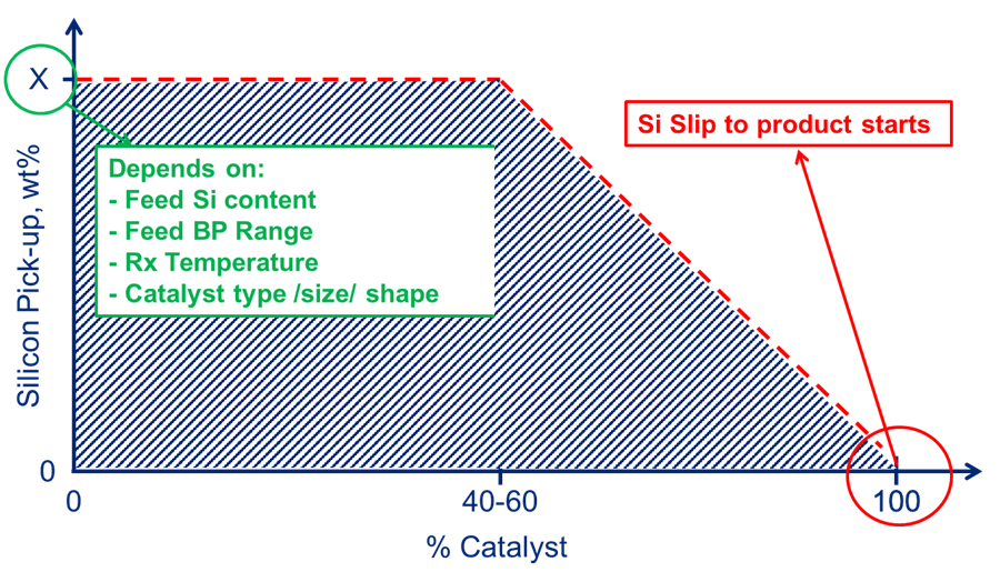
Fig. 2 – Max silicon capacity.
How sharp the pick-up profile is, and as such what percentage of maximum silicon pick-up breakthrough will occur, depends not only on catalyst type, size and shape but also on 1) feed silicon content and 2) liquid hour space velocity, or LHSV (Figure 3). Please check with your catalyst supplier for the expected pick-up tailored to the respective unit conditions.
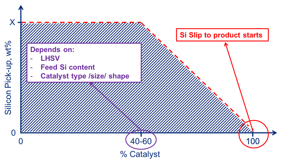
Fig. 3 – Silicon laydown profile.
Please see Haldor Topsoe’s previous AFPM responses on the subject of silicon poisoining for mitigation steps including proper catalyst design when processing silicon containing streams.
As for consequence to the downstream reformer, the silicon is a permanent catalyst poison that cannot be removed via regeneration.
Year
2019
Submitter
Process