Question 26: What do you do to predict Silicon breakthrough in a naphtha hydrotreater? What are the consequences to the downstream units if breakthrough occurs?
AMIT KELKAR (Shell Catalysts & Technologies)
The primary source of Silicon is the anti-foam injection at the coker. Silicon is also present in a wide variety of crudes including Maya, Canadian syncrudes and Venezuelan. It may show up in straight run naphtha due to use of Silicon based additives in upstream crude production and pipeline operations.
One way to monitor breakthrough is to track cumulative Silicon content of feed compared to the design Silicon capacity of the installed catalyst system. This requires regular feed analysis. A reasonable estimation of feed silicon can be obtained by detailed spent catalyst analysis from prior cycles. Monitoring the progression of dT across the catalyst bed is a qualitative way to monitor Si breakthrough. The catalyst at the top of the reactor gets saturated with Si first resulting in shift of dT to the lower portion of the bed. This Si “wave” can be tracked by means of a plot of percent dT for each individual bed or even sections of the same bed provided adequate thermometry is available.
Another way to monitor Si is by means of a rigorous kinetic model while splits the catalyst bed into multiple “slices” and estimates an overall Si profile for different cycle lengths.
Si deposition preferentially poisons the HDN function of the NHT catalyst. In some cases, product nitrogen slip precedes Si slip. Nitrogen specification for reformer feed is 0.1 – 0.5 ppm. Increased N slip strips the chloride off the reforming catalyst and affects the metal / acid balance. It leads to fouling of recycle compressor blades, stabilizer trays, feed / effluent exchangers and overhead coolers due to deposition of ammonium chloride (NH4Cl).
High silicon (target < 0.1 ppm) in the reformer feed blocks the active sites and reduces regeneration efficiency by impacting Pt dispersion and Cl adsorption.
JOE RYDBERG (CITGO)
Silica capacity can become a run limiter especially on units that process Heavy Coker Naphtha. Typically the reactors in these units will contain a significant amount of high surface area Silica Guard catalyst in addition to the high active main bed catalyst. Silica is analyzed in the feed to ensure the unit is “on pace” with meeting its cycle length target. Silica pickup is temperature dependent. Work with your catalyst supplier to provide a total Silicon “trap capacity” number for the reactor and individually for the silica trap material, mainbed catalyst, and so on. At the end of the run, the Silica lab numbers are totalized and compared to the weight of Silica the spent catalyst “captured”. Each layer needs to be sampled and analyzed. Typically these compare pretty closely (10-20% or so). Need to make sure not to confuse Silica with Silicon. Work with your catalyst suppliers to potentially add additional Silica Guard catalyst and extend the next cycle. Tracking Silica can be an effective method to predict and schedule catalyst changes several years out. Looking at the Silica levels in catalyst samples at the bottom of the bed will also ensure that Silica hasn’t broke-through into the reformer. Typical consequences of Silica (which is a permanent poison) breaking through into the downstream reforming unit is loss of catalyst activity and yield
KA LOK (Honeywell UOP)
Regular monitoring of silicon levels in naphtha feed and reload of the hydrotreater catalyst as needed are tools to safe guard downstream catalytic units, primarily catalytic reformers. Generally silicon in naphtha hydrotreater feed is from byproducts of delayed coker antifoam. Analysis of the feed for silicon content should be on a composite sample collected over a coke drum cycle to determine a representative average concentration. Cumulative mass of silicon throughout the hydrotreater cycle can be tracked against the silicon capacity of the reactor catalyst inventory represented by the catalyst supplier. Although contaminant silicon will deposit in a relatively narrow band progressively through the reactor, a safety margin to account for catalyst bed bypassing and the length of the silicon removal zone should be included in estimating silicon breakthrough out of the hydrotreater. Periodic sampling of reactor effluent for silicon analysis near estimated end of run can be used to verify the estimate.
A hydrotreating process unit is commonly used to remove metals in the naphtha prior to feeding to a catalytic reforming unit, such as a UOP PlatformingTM unit. Reforming catalyst is very sensitive to silicon contamination. Silicon is an irreversible support poison. It reduces chloride retention and accelerates platinum agglomeration. At elevated levels this could lead to poor catalyst performance, increase in cracking, lower C5+ yield and lower activity. In addition, regular analysis of reforming catalyst for silicon concentration provides additional protection against poisoning.
SERGIO ROBLEDO (Haldor Topsoe, Inc.)
As stated in previous AFPM Q&A’s answer books (see 2014 and 2016), silicon will impact HDN activity to a greater extent than HDS (see Figure 1). Therefore, a good way to measure silicon pick-up is by tracking the feed and product nitrogen. The %HDN, and normalized WABT HDN, can then be calculated and the decline over time can be tracked.

Fig. 1 – Silicon impact on catalyst activity.
It is recommended that feed and product silicon be measured. This will allow the pounds of silicon being placed on the catalyst to be calculated and help determine when a Si breakthrough will occur. Alternatively, antifoam usage at the coker unit can be used to estimate pounds of silicon entering the naphtha unit. Check with your chemical supplier as to 1) how much pounds of silicon are present in each gallon of antifoam and 2) what percentage of that ends up in your naphtha cut, based on cutpoint.
Another important factor is to understand the silicon capacity of the installed catalyst system and its pick-up profile. A standard/max theoretical pick-up number should not be used to estimate breakthrough. Silicon capacity is dependent not only on the catalyst installed, but feed and operating conditions of the unit it is installed in. Maximum silicon pick-up in a given unit is dependent not only on catalyst type, size and shape but also on 1) silicon content in the feed, 2) feed boiling point range and 3) reactor operating temperature (Figure 2).
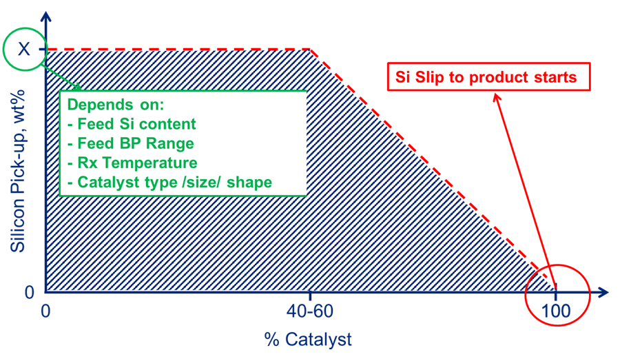
Fig. 2 – Max silicon capacity.
How sharp the pick-up profile is, and as such what percentage of maximum silicon pick-up breakthrough will occur, depends not only on catalyst type, size and shape but also on 1) feed silicon content and 2) liquid hour space velocity, or LHSV (Figure 3). Please check with your catalyst supplier for the expected pick-up tailored to the respective unit conditions.
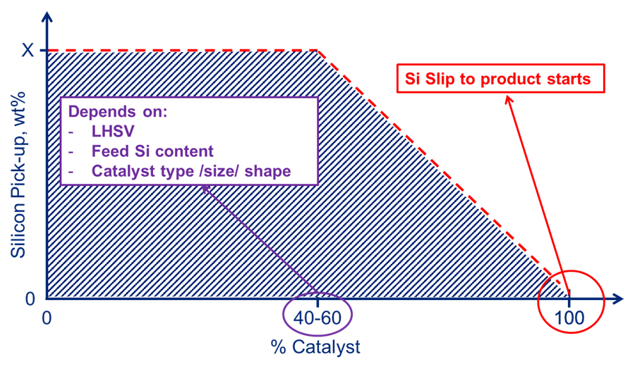
Fig. 3 – Silicon laydown profile.
Please see Haldor Topsoe’s previous AFPM responses on the subject of silicon poisoining for mitigation steps including proper catalyst design when processing silicon containing streams.
As for consequence to the downstream reformer, the silicon is a permanent catalyst poison that cannot be removed via regeneration.