General Session: Potpourri (Artificial Intelligence) : The Advent of Artificial Intelligence (AI) in Environmental Management: Impacts, Opportunities, and Risks in the Fuels Refining and Petrochemical Industry
This conference session navigates the environmental-related opportunities and challenges of artificial intelligence (AI) implementation in the refining and petrochemical industry. Our expert panelists will discuss the current state of AI and machine learning technologies, practical applications of AI in the environmental field, conceivable legal risks to using AI, and possible impacts of public access to these AI tools and available environmental data from our facilities.
Speakers: Kyong Song, Amy McDonald, Jed Anderson, Jon Bloomberg
Moderator: Joel Trinkle, Phil Fish

General Session: BWON/QQQ: New BWON Enforcement Initiatives (It's Y2K All Over Again)
This panel discussion will provide legal and industry perspectives regarding the recent new wave of EPA BWON enforcement including highlighting the common areas where EPA has identified deficiencies in proper equipment and control device design and operations. The panel will also share insights into future requirements that will likely set a new bar for enhanced monitoring and compliance similar to the global consent decrees of the early 2000s.
Speakers: Deever Bradley, Jim Fain, Justin Savage
Moderator: Dave Wall
Question 5: What is the panel's experience with hydrotreater fouling/poisoning issues arising from processing synthetic or bitumen-derived crudes? How can the impact be mitigated?
BODOLUS (CVR Energy)
This question is directed more at the bitumen-derived type of crudes. I call all of them mined crudes from tar sand sources. We process a lot of these materials at our two refineries. The crude goes under the name of Western Canadian Select, which oftentimes is not very select. Next, I want to review the categories of contaminants. You can have the elemental poisons, arsenic, and phosphorus. Typically, they are associated with the origins of the heavy oil deposit, or perhaps they are introduced during processing or transport to the refinery. We have run across organic bound chlorides. Of course, you will have some silicon contamination if some of the material was coked up north and produced naphtha where you have the silicon liability. Iron and other metals can be present in the oil, again, either introduced during processing or as part of the original deposits. One interesting situation I alluded to in a few of the other questions is that the mineral contaminant, and the clays associated with these mined tar sands, are suspended by chelating hydrocarbons. As you hydroprocess those tar sands, you remove the stability of the chelating agents, and the clays may indeed deposit on you.
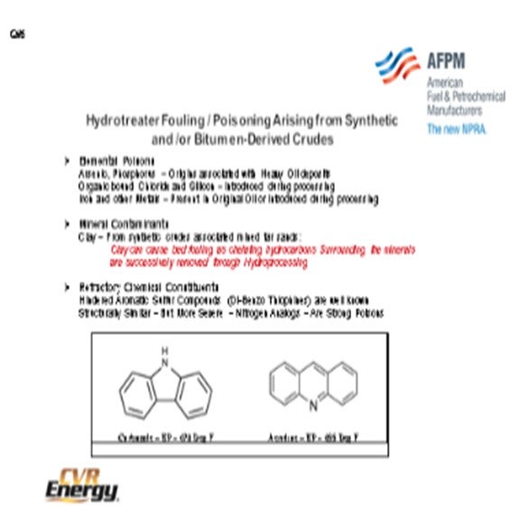
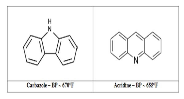
I think the question before was targeted at the next issue; that is, the refractory chemical compounds that are left behind. If these compounds have been processed before, then all that is left are the tough guys. I know that over the years, there has been a lot of emphasis put on the hindered aromatic sulfur compounds, dibenzothiophenes, and hindered dibenzothiophenes. As analytical techniques improved and you were able to look at these trace compounds a little better, we also found some nasty nitrogen-based compounds. These are similar, but they are nitrogen analogs to the dibenzo family. There is the five-membered nitrogen carbazole, and then there is a six-membered nitrogen acridine family. All of these boils between the range of 650°F and 700ºF. They are very intractable compounds. Note that the acridine shown on the right side of the slide does have an unshared nitrogen pair that goes after the metal centers, which can really tie up your catalyst.
As far as mitigation methods, I would like you to keep this mantra in mind: Treatment without proper diagnosis is malpractice. Typically, that is associated with doctors; perhaps, less likely associated with lawyers, but I feel that engineers also need to practice this mantra. So, unless you really know your poison, you will not be able to deal with it effectively.
In the mitigation plan, of course, you can always try to abate the problem externally. Avoid that crude or those particular types of materials in your refinery. If you cannot avoid them, then go about possibly removing them at an upstream unit through desalting or filtration. Then as another option, perhaps you could chemically neutralize it if you are dealing with a chemical compound.
As the fallback position during a turnaround, it is very important to meet with your catalyst vendor and stack the bed in your favor. There are many different poison guards availableto do that including silicon traps, arsenic guards, metal traps, and asphaltene destruction-type catalysts. Talk to your catalyst vendors because they will have a list of these guards that you can evaluate. So it is very important to strategically grade your bed for both activity and contaminant capture. Again, catalyst selection is important further down in the bed for dealing with the tougher actors.

ESTEBAN (Suncor Energy, Inc.)
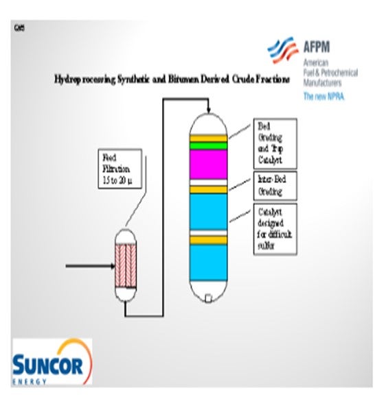
For obvious reasons, at Suncor Energy, I had access to several folks who have a great deal of experience processing synthetic crudes. We have found that a typical issue in our units is feed filtration, and we continue to struggle with it. However, good feed filtration at the 15μ (micron) to 20μ range helps prevent fouling and then, obviously, bed grading and trap catalyst.Trap catalyst targeting arsenic and silicon is used because those are the typical compounds we find to be issues. Inter-bed grading, if required, can also prevent some of the pressure drop built across the reactor.
The other key point Chris mentioned is that the synthetic crudes can often be deceiving because they may look like they have low sulfur content. But in reality, you are left with all of the difficult sulfurs. So, I would recommend pilot testing, if you are considering synthetic crudes, just to ensure that you have the appropriate activity required in your reactor.
OHMES (KBC Advanced Technologies, Inc.)
I have a couple other points about some of the contaminants. In addition to what Chris covered, we have been hearing about titanium and, in some cases, mercury. At the Annual Meeting this year, there was a really good paper and presentation on mercury. It is one of those issues where you need to be a little more eyes-wide-open about what might be coming into the plant now as you bring in these crudes. As some people have been saying, it depends on what you are getting.
This slide shows a simple graphical representation of the upgrading process. If you are getting the synthetic crudes, again, the properties can be deceptive. You think you are getting low sulfur/low nitrogen feedstock, but these materials have typically been highly processed already such that the remaining contaminants are difficult to remove. It also really depends on what else might be blended with it if you are getting synbit or dilbit. Most people are aware of the blends they are buying, but it should be monitored.
I know we talked about the Canadian crudes, but there are also the Venezuelan upgraders. We have had clients processing that material and seeing wide variations, depending on how the upgraders are performing. For instance, if the upgraders are having maintenance issues, the crude buyers may go from receiving no-bottoms crude to having a lot of bitumen in the purchased crude.
Another issue to mention is exchanger fouling. Again, people are seeing this problem in the crude vacuum units. Proactive crude quality tracking is an area where refiners have been lulled into complacency and are not actively completing. But with the new crudes being brought in, you want to make sure you have a good understanding of what you are getting. Particularly for those who are either processing this material or shale crudes, crude buyers are asking – upfront and in advance – about some of the completion chemicals being used by the upstream companies. This way, they will be able to set some limits in the crude that they may be getting and have an understanding of what is coming down the pipe in order to plan for it.
KEVIN PROOPS (Solomon Associates)
James, you mentioned filtering the reactor feed. Are you using cartridge or backflush-type filters? If it is backflush, where are you sending the backflush material?
ESTEBAN (Suncor Energy, Inc.)
The answer is “yes” in all cases. At the Denver Refinery, that has been a struggle for us. We have cartridge filters. We have not been very successful at feed filtration, although we are continuing to work on it. In Edmonton, we have a backwash system. The backwash is sent as feed to the FCCU.
BODOLUS (CVR Energy)
Our facilities and historic lab have experience with both backflush and cartridge. We have good relationship with the cartridge vendor. An interesting tradeoff in the automatic backwash filters is that the problem often comes and goes without you knowing about it. What is interesting with the cartridge filtration is that if you start buying a lot of cartridges, management wants to know why. You can then deal with the problem, if it is intermittent. Both can work, if appropriately applied. I have had experience with both, but filtration is key. On some of our units, we have had up to a six-year run. You cannot get there without filtration.
DAN WEBB (Western Refining)
Synthetic crude is a full boiling range material. If it is not, would you say that it is susceptible to polymerization? Do you have to keep it oxygen-free when you are handling it?
ESTEBAN (Suncor Energy, Inc.)
The crude itself?
DAN WEBB (Western Refining)
It is best to keep Lifecycle in a nitrogen-blanketed environment. Does it age when exposed to air?
ESTEBAN (Suncor Energy, Inc.)
Not that I know of.
OHMES (KBC Advanced Technologies, Inc.)
You blended in a lot of coker material, so all that polymerization material forms; but now, it is blended in with the crude, so to speak. We are not really seeing a lot of people nitrogen-blanketing their tanks. It is aged; it is formed; and now it can separate out differently. “What hurts you inside the plant” is actually a question we will cover later. The question asks about when you have olefin problems inside the refinery.
LEICHTY (Chevron USA, Inc.)
My experience is that the synthetic crudes in Canada are either derived from cokers, VGO hydrocrackers, or resid hydrocrackers. If derived from cokers, the products are almost always hydrotreated; and thus, no olefins should be present. As such, there should be no storage requirements that differ from conventional crude oils. Similarly, there are no special storage considerations required for synthetic crude oils derived from VGO and resid hydrocrackers since there should be no olefins present.
BODOLUS (CVR Energy)
Synthetic type crudes have a higher probability of containing elemental poisons such as arsenic, phosphorus, organic-bound chloride and silicon. Some of the contaminants track back to the original heavy oil deposits (arsenic and phosphorus) while other contaminants are introduced during the production of the synthetic crude (silicon and chlorides). For synthetic crudes associated mined tar sands, mineral contaminants such as clay can cause bed fouling as chelating hydrocarbons surrounding the minerals are successively removed through hydroprocessing.
The chemical constituents of the synthetic crude will include the residual “refractory” type compounds remaining from previous hydroprocessing. Synthetic crudes will have proportionally more aromatic sulfur and aromatic nitrogen compounds in the heavy ends of the distillate cut. By now, most synthetic crude consumers are familiar with how difficult the hindered dibenzothiophene is to process, but there are also nitrogen based analogs that can be even more challenging. The carbazole family represents the five-member nitrogen bound dibenzo aromatic compound while the acridine family is a six-member nitrogen bound dibenzo aromatic compound. Acridine is a more potent inhibitor of hydroprocessing than carbazol (C12H9N) due the basic character of the unshared pair of electrons in the aromatic plane.
Mitigation needs to be targeted at the specific cause and addressed on a case-by-case basis. Proper diagnosis of the problem is the key to treatment. Confirm the presence of the poison or fouling component with analytical data or process information. For elemental chemical poisons, apply strategies to remove the contaminant in an upstream unit or obtain poison specific bed material in the reactor unit. For mineral based fouling in secondary beds, catalyst size selection may be helpful in increasing bed void volume. For refractory sulfur and nitrogen compounds seek catalytic solutions that will help optimize severity in the active reactor beds.
ESTEBAN (Suncor Energy, Inc.)
There are several challenges with processing synthetic or bitumen-derived crudes. Fouling issues are typically a result of problems in upstream units and poor feed filtration. Good feed filters and installing a graded bed system to trap out particulates will address the fouling issues. However, not all contaminates can be filtered and some materials can come out of solution with increased saturation as material is processed through the reactor which, if possible, can be mitigated by the use of graded material on the top of subsequent beds.
To mitigate poisoning of active catalyst, proper amounts of catalyst in the guard beds, ahead of the active catalyst beds is required for contaminant removal/capture of poisons. Suncor’s experience has identified the main poisons to be nickel, vanadium, arsenic, and silicon. The initial challenge with such feeds is the measurement of the concentration of poisons. Suncor has found arsenic and silicon concentration to be especially challenging as outside lab results widely vary and some are in error by a factor as high as 10. It is our practice to have samples processed by several independent labs to confirm results and analyze spent catalyst for metals loading. The following discussion describes the effects and potential solutions for feed streams with these poisons: Arsenic is present in the bitumen-derived crude in the form of alkyl-arsenic compounds.
Arsenic interacts more strongly with nickel than other metals used in hydrotreating catalysts. Consequently, it has a severe poisoning effect on NiMo (nickel molybdenum) catalysts. Arsenic (As) reacts with nickel to form nickel arsenide (NiAs). Based on this stoichiometry, a nickel-based arsenic trap can theoretically pick up about 1.28 wt% As for each 1 wt% Ni on the catalyst. The actual capacity will depend on process conditions (in particular temperature) and the concentration of arsenic in the feed. Arsenic is a permanent poison, so it is not removed via regeneration or other means. Arsenic has an affinity for Ni which provides an opportunity for efficient trapping. Arsenic trapping capacity of trap catalyst available generally varies from 2 wt% to 4%, but arsenic slippage to active catalyst can happen before the trap bed becomes fully saturated. Experience at our Edmonton refinery has shown that active NiMo catalyst can pick up ~1 wt% arsenic as well.
The typical source of silicon in these feed streams is Antifoam chemicals used in coker units which become highly concentrated in the naphtha cuts. However, upgraders and refiners have been known to try heavier anti foams to distribute silicon into distillate as well. Accurate measurement of the concentration of silicon in feed streams can be difficult and is often provided by our catalyst vendors. Silicon forms a chemical bond with the alumina surface and hinders access to the active sites. Suncor’s experience has demonstrated trap catalyst can usually uptake 6 wt% to 9 wt% silicon [sometimes reported as silica (SiO2) which would be double in wt%]. That being said, silicon uptake is highly temperature dependent and catalyst vendors can provide pickup information regarding performance specific to each unit.
Nickel and vanadium are typically a concern above 2 ppm (parts per million). These poisons are found in high concentrations in bitumen-derived feeds but usually end up in vacuum tower bottoms products. In order to prevent high concentrations of these metals in feed streams to hydroprocessing units, careful monitoring and control of vacuum gas oil endpoint is critical. Abnormal and improper vacuum tower operations can cause a spike in nickel and vanadium in product gas oil streams. Proper attention should be paid to wash oil grid operation and potential grid damage identified to prevent high endpoint material in the gas oil streams. As well, vacuum tower product streams should be properly managed during upset operating conditions to avoid contamination of downstream unit feed streams.
In addition to fouling and poison, mitigation often these feeds can be more difficult to treat than expected due to previous treating. While on the surface some synthetic feeds appear to be low in sulfur and easy to treat, they can be deceiving because they have been previously treated and the sulfur left in the streams is more difficult to remove requiring higher reactor temperatures. In order to properly predict the impact of such feeds on each specific unit, we recommend pilot testing be performed to provide reactor performance and life cycle predictions.
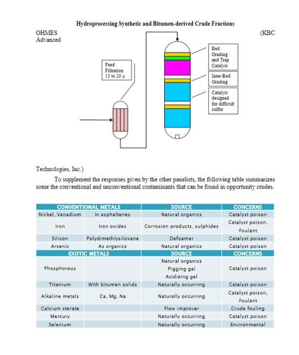
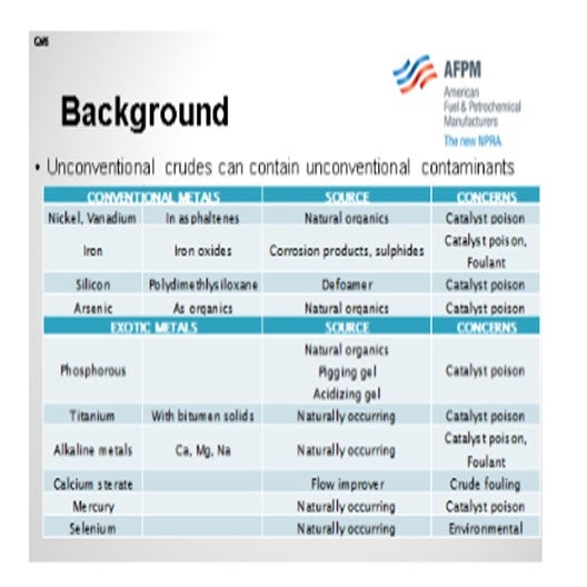
Several of the exotic contaminants are ones that most refiners do not typically track or follow. However, those refiners processing opportunity crudes have become more active in looking for these contaminants in their crudes and watching for the impact on downstream equipment. In addition, the level and “location” of said contaminants is strongly dependent on the source of the opportunity crude. The following simplistic graphic summarizes the different sources and production methods for unconventional crudes from upgraders.

Therefore, understanding the source and production method provides valuable insight into the types of contaminants to expect and how these will impact the plant.
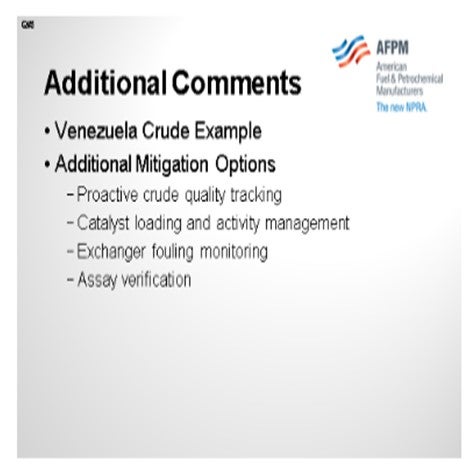
When discussing opportunity crudes, most think of Canadian synthetic crudes or shale oil crudes like Bakken and Eagle Ford. However, other crude sources exist and are processed in the industry. Venezuela has been running upgraders since the late 1990s and though their production levels continue to fall, refiners are still processing the material. Those processing Zuata crudes can confirm that the quality and cut range content vary substantially, depending on how the upgraders are being operated and how the agreements are arranged.
Some additional mitigation options are recommended:
•Those successfully processing opportunity crudes are actively monitoring crude quality, both on properties and cut range material content.
•Catalyst grading and activity tracking and management are more critical now than ever. Unconventional contaminants are highly poisonous to catalyst and can quickly deactivate catalyst.
•Exchanger fouling monitoring has now become more important than just understanding the impact on throughput and energy conservation. Exchanger monitoring packages, such as Petro-SIM™’s HX Monitor, are very useful in understanding how exchanger fouling is occurring in the facility, particularly when operating conditions and feedstock qualities are varying frequently.
•When planning and scheduling for these crudes, ensure the assays are representative of the actual material processed in the plant. While some discrepancy will always occur, having representative assays for various mixes, fields, and sources will help the refinery generate plans and operating schedules that are achievable and have sufficient flexibility to manage the natural swings and variations that occur.
BRUCE WRIGHT (Baker Hughes)
If the synthetic crude is fully hydrotreated, then few problems would occur, similar to a straight run hydrotreater feed. If the synthetic crude is only partially hydrotreated, or not hydrotreated at all, then polymer formation and deposition in the feed/effluent exchangers and reactor bed could be experienced. Baker Hughes LIFESPAN™ antioxidants, anti-polymerants, and antifoulants can effectively control polymer formation and fouling in both the feed-effluent exchangers and reactor bed.
HIROSHI TOSHIMA and STEVE MAYO (Albemarle Corporation)
Synthetic crudes from Canada, Venezuela, Urals, and elsewhere often involve inherent arsenic contamination. The effects of arsenic can be seen in all units processing synthetic feedstocks, but coker naphtha units are typically the most severely impacted. Arsenic has adverse effects on HDS (hydrodesulfurization) and HDN (hydrodenitrification) activity of hydrotreating catalyst. As little as 0.5 wt% arsenic can reduce HDS activity by 30% to 50%. Hence, it is important to protect the main bed catalyst of hydrotreaters experiencing arsenic contamination. Arsenic guard catalysts can be placed at the top of the reactor to contain arsenic penetration into the main catalyst bed for much of the cycle. These catalysts typically have high nickel content to which the arsenic is attracted.
Synthetic feedstock processed in delayed cokers produces lighter products containing, not only arsenic, but also silicon. Silicon deposition on arsenic trapping catalysts can severely impact the catalysts arsenic capacity since it covers the nickel site to which arsenic is attracted. Arsenic traps with high silicon capacity often show superior arsenic capture performance in these units.
GREG ROSINSKI, CHUCK OLSEN, and BRIAN WATKINS (Advanced Refining Technologies)
There is large variation in the quality and types of synthetic crudes, and there can be problems with trying to process many of them. In general, synthetic crudes can be classified into two basic types.
One is a blend of upgraded naphtha, distillate and gas oil range with no resid or bottoms material included. Fully upgraded synthetic crudes are more difficult to treat than might be expected from a typical feed characterization. The upgrading process typically includes several hydrotreating and hydrocracking steps, as well as coking processes to lighten up the material to make its flow characteristics easier to handle. The molecules left in the oil are the more refractory and difficult to remove species. The fractions that are pulled from the refinery’s crude processing units, however, typically have a high API along with the lower sulfur and nitrogen masking these difficulties. These crudes can also pose a difficulty with the presence of silicon which can be introduced from the coking process or through flow enhancers added after processing, and if left undetected will poison downstream hydrotreaters.
The other crude type utilizes the whole bitumen including bottoms which has been blended with other sweet synthetic or more conventional crudes. With synthetic crudes that do contain bottoms there can be significant problems with poisoning. Since these types of synthetic crudes contain bitumen they can have higher levels of Ni+V in the HVGO (heavy vacuum gas oil) compared to similar boiling range materials from conventional crude oils. This can be dealt with in the hydrotreater using an appropriately sized bed of demetallization catalysts, such as ICR132 and ICR161. Some of these crudes may also contain silicon, from upstream coking process and/or arsenic present in shale derived oils. In these cases, a combined silicon/arsenic guard such as AT734G from ART can be used to help mitigate the impact of these poisons.
Many of the synthetic crudes may also contain very fine particulates of clay or sand that are associated with asphaltenes or other heavy polycyclic molecules. These particulates can be removed through proper use of the desalter to avoid crude tower fouling. However, these small particulates typically <5 microns, when not properly removed, can pass through feed filters into the catalyst beds resulting in pressure drop issues. Often this pressure drop can occur is lower catalyst beds due to the denaturing effect of hydrotreating on the heavy molecules. The removal of sulfur, nitrogen, and aromatic saturation, as well as the heat and hydrogen present, can release the fine particulates further into the hydrotreater and cause them to precipitate out. Use of larger void spaced catalyst can help alleviate this problem to some level; however, we are not aware of anyone who has found a solution that completely alleviates this problem.
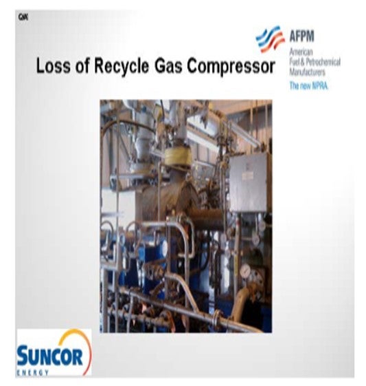
Question 6: Following an emergency shutdown that includes the loss of the recycle gas compressor, is it possible to quantify the effect on catalyst deactivation? What are the Best Practices to minimize catalyst deactivation?
ESTEBAN (Suncor Energy, Inc.)
This picture shows my favorite compressor at the refinery. She and I have a love/hate relationship. We installed a gas oil hydrotreater in 2006, a new unit with this compressor, and we have a great deal of experience with emergency shutdowns. In fact, the unit has shut down over 60 times in the last six years; so if you do the math, it is once a month. I have had the personal pleasure of being both an operator on the unit and an engineer for the unit, and then revamping it while still dealing with all of the compressor shutdowns. So, for us, that has offered some learnings and some struggles as well.
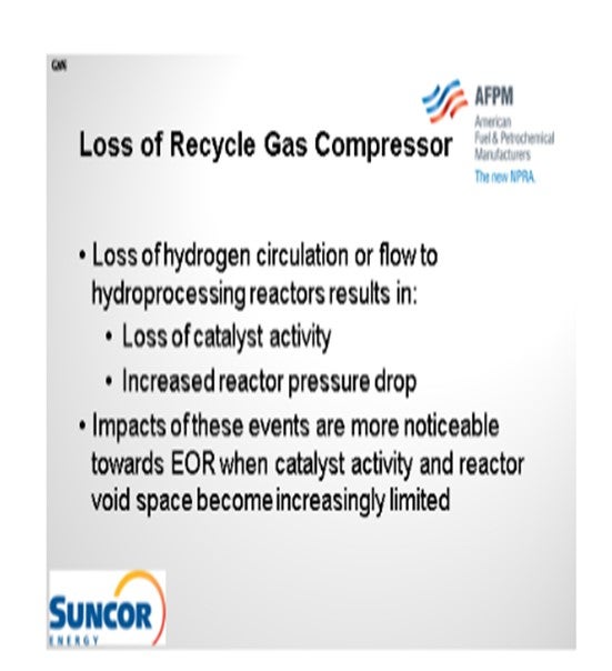
The primary impacts of loss of hydrogen circulation or flow. If you have a once-through unit are obviously loss of catalyst activity and increased reactor pressure drop. In some cases, you do not notice that these are occurring; so, at the start-of-run, you have excess void space and excess activity in the reactor. The same event may cause an increase in pressure drop, an increase in coke in the reactor, or a loss of active sites in the catalyst or access to active sites. You cannot really tell until you get closer to the end-of-run. As a result, we have experience seeing step changes in pressure drop and catalyst activity as a result.
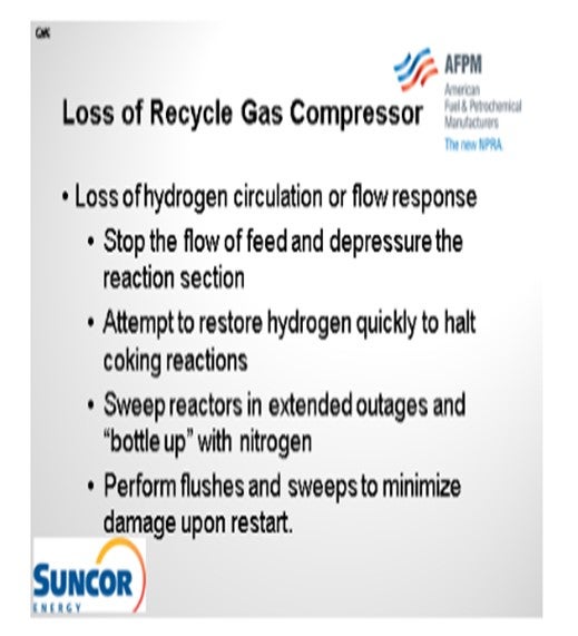
At Suncor, we have found several effective methods for minimizing the impact of loss on our hydrogen recycle gas compressor. First, we stop the flow of feed and depressure the reaction section. This action clears as much of the oil off of the hot catalyst as possible to avoid coking reactions that occur in low hydrogen partial pressure environments.
Secondly, we obviously attempt to restore hydrogen quickly to halt coking reaction in order to restore the circulation of hydrogen. For obvious reasons, this is the most advantageous action because it allows us to sweep the oil off of the catalyst and restore the hydrogen partial pressure; in addition, we can prevent liquid from pooling the reactor.
Third, we sweep reactors in extended outages and bottle up with nitrogen. So in the event that hydrogen cannot be restored quickly, the reactor should be swept by whatever means to the flare to clear as much oil from the catalyst as possible and then bottled up. At Denver, our high pressure units have integrated hydrogen circuits. While they are separate in operation, we also have an integration line between them. We just call it the ‘sweep gas line’, which is exactly how it is used: to sweep the reactor when it shuts down every month.
Lastly, where we have really gained a lot of experience and understanding is by using the flushes and sweeps recommended by catalyst manufacturers. Every manufacturer will have its own separate procedures on how to perform the flushes and sweeps. The hot strips – and then diesel and LCO (light cycle oil) flushes – are actually very effective in minimizing the impact of a loss of recycled gas event, although they do not completely mitigate the issue.
CARLSON (Criterion Catalysts & Technologies)
First of all, when discussing the response to an emergency situation like a recycle gas compressor, remember that not every unit or situation is the same. Care should be taken when applying any changes to existing procedures.
Following an event like a loss of the recycle compressor, it is, of course, important that the on-hand procedures provide a safe and reliable process for taking a potentially unsafe, undesired situation to a safe position. While consideration of HS&E (health, safety, and environmental) and equipment protection are key, a few additional steps in the procedures can minimize the potential of further lost opportunity due to any resultant catalyst damage.
Our response is a little bit different depending on whether it is a hydrotreating or hydrocracker application. For conventional hydrotreating applications (alumina-based catalyst systems), the first step is to remove heat from the reactors. This elimination involves tripping the furnace and removing any highly exothermic cracked stocks. By leaving the feed pumps on and maintaining makeup hydrogen, if possible, reactor temperatures will often begin to drop, thereby minimizing the incident. If the recycle compressor can be restarted within a short period of time, less than 15 minutes, then the impact on unit operation should be minimal. If exotherms continue to climb and do not show signs of stabilizing, then controlled depressurizing of the reactor will return the unit to a safe condition. Of course, this will trip the feed pumps and makeup compressor, initiating the sweeping of the reactants from the unit.
If the recycle compressor cannot be restarted within a short period, we recommend continuing cooldown to less than 400ºF and then following your procedures to depressure the unit to a safe holding condition.
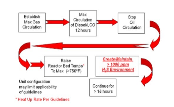
Following the completion of any required maintenance, the start-up procedure should include steps to perform a warm diesel flush and possibly a hot hydrogen strip.
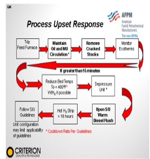
In the Answer Book, I have included a list of steps to consider when performing a restart after an extended unit trip. A key consideration during these types of unit responses is to take steps to minimize the exposure of the sulfide catalysts to a reducing environment. This means that when temperatures are above 450°F to 500°F, we need to ensure that H2S is present. Again, it is particularly important when doing the hot hydrogen strip that during the restart, you confirm that no pure hot hydrogen is being circulated. That, in and of itself, can have negative impacts on the catalyst.
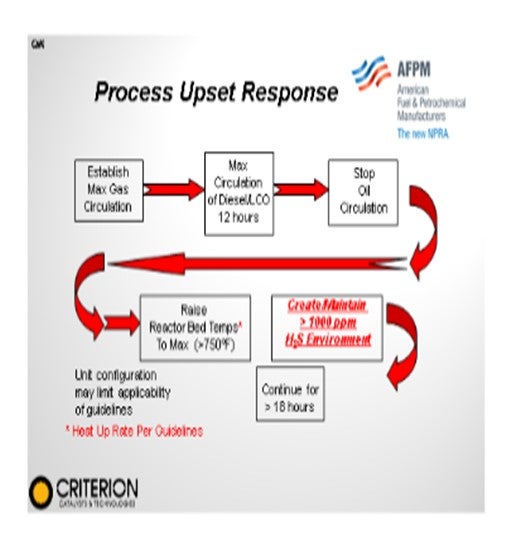
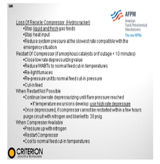
This next slide contains a lot of text that summarize the steps we recommend for hydrocracker operations. In the Answer Book, we cover the material in more detail. For hydrocracking applications, we have a further consideration for units with cracking catalysts. We advise that gas and liquid feeds be removed from the unit and that a low-rate depressurization be used to begin the sweep of reactants from the unit immediately following the trip.
After taking the unit to a safe condition, the obvious question arises about the impact on the catalyst. While the only way to evaluate and quantify catalyst condition is with a post-restart operational test run and pulse test, some qualitative indications of catalyst condition can be made prior to a restart, including:
•Time at temperature of the catalyst beds
•Hot spots observed during the event and subsequent cooldown
•H2S presence if temperature is greater than 500ºF
•Transient review of temperatures during cooldown
•review of procedure response
The other consideration is the point we are in the operational cycle. At SOR (start-of-run), the units tend to bounce back well; but if we are late in the cycle where the operating temperature is higher and contaminant loading has already elevated, then the impact of these trips tends to be felt more.
SERGIO PIMENTEL (CITGO Petroleum Corporation)
If feed is removed from the unit, it is recommended to immediately shut down the amine column, if you have amine circulations, to preserve H2S in the system. But if that trips the recycle compressor, then you might not want to do it because you would probably be depressurizing the unit quickly to a fuel gas system or to a flare. Hydrogen is not coming back to the reactor, so you should leave the amine column running.
CARLSON (Criterion Catalysts & Technologies)
That is correct. It is important to remember that if your beds are still at elevated temperatures upon unit restart, then we will again need to protect the catalysts from potential hydrogen reduction. In this case, we recommend that upon the restart of the recycle compressor, the amine system should be kept out of service to allow the H2S content to build up in the recycle circulating gas to prevent possible reduction.
SUBHASH SINGHAL (Kuwait National Petroleum Company)
We do it differently at KNPC. When there is loss of a recycle gas compressor, we keep the liquid feed going in and use this as a cooling media after reducing the hydrogen partial pressures and bringing down the temperatures. Liquid feed is used as a cooling media.
CARLSON (Criterion Catalysts & Technologies)
Right. That was what I mentioned on the first slide. For conventional hydrotreating applications, if it is just alumina-based catalysts, we recommend that you leave in your straight run feed. You will want to pull your cracked feeds; but yes, you can cool down your reactors on a conventional hydrotreating unit with straight run feeds. It is just in hydrocrackers that we suggest removing all feeds.
SUBHASH SINGHAL (Kuwait National Petroleum Company)
I think a lot of those hydrocrackers are not straight run feed. The hydrotreated feed from it mostly exists at desulfurization. We still keep in the liquid feed, and that has been quite effective.
CARLSON (Criterion Catalysts & Technologies)
Exactly, and you will see a lot of variations on the practices within the industry.
LEICHTY (Chevron USA, Inc.)
At Chevron, we have concluded that it is always better to leave feed in the reactor upon loss of recycle hydrogen, regardless of whether it is a hydrotreater or hydrocracker. The basic premise is that without recycle hydrogen or feed, there is almost no flow through the reactor to carry away heat. Also, reactor temperature indication is stagnant, and there is a higher probability of undetected localized hot spots that could lead to a temperature excursion. If feed is left in the unit, excess heat in the reactor has a medium to be carried away, thereby minimizing the potential for de-methylation-type hydrocracking reactions and temperature excursions. In addition, with the flow in the unit, operators have a better picture of what is thermally happening in the reactor, which enables them to quickly respond to a temperature excursion by depressuring the reactor.
ESTEBAN (Suncor Energy, Inc.)
For units equipped with a recycle gas compressor, it is one of the most critical pieces of equipment; and as such, an emergency shutdown of this critical piece of rotating equipment can result in significant adverse impacts to unit operation and catalyst performance. Similarly for units without recycle streams that operate in once-through fashion, the loss of hydrogen flow to the reactor can have the same detrimental impacts. The primary concern with the loss of recycle gas or the loss of hydrogen flow to the reactor in general is the potential for coking due to the presence of oil on hot catalyst with significantly reduced hydrogen availability partial pressures. The result of coking can be seen both in a loss of catalyst activity and ultimately an increase in reactor pressure drops. Given the nature of the emergency and the state of the unit before and after a shutdown, it is possible to determine the impact on catalyst activity once the unit is brought back online and is in stable operation.
The Suncor Energy, Inc. Denver Refinery has a great deal of experience with loss of recycle gas compressor events on a gas oil hydrotreater. The recycle gas compressor has seen very poor reliability primarily due to electrical issues related to the variable frequency drive unit that is used as the driver for the compressor motor. On average once a month this machine and subsequently the entire unit experience a complete shutdown. While some efforts have been successful in improving the compressor’s performance it remains one of our big rocks. However, on a positive note the experience gained from these events has provided us with supporting data to confirm our Best Practices. Typically, most trips early in a catalyst run do not appear to be as detrimental to reactor performance as those later in the run due to the excess void space and catalyst activity available. It is possible to see the impact from these events on catalyst activity simply by comparing the normalized reactor weighted average bed temperature (WABT) prior to and post shutdown, but it is our experience that noticeable step changes in WABT are more pronounced and noticeable towards the end of run. In conjunction with catalyst activity the effect on reactor pressure drop is also more noticeable towards the end of run. Both catalyst activity and reactor pressure drop are related here because loss of activity is a direct function of the formation of pressure drop due to coking and sloughing of materials from upstream equipment.
In order to minimize the impacts of loss of hydrogen events our experience has shown that the following Best Practices are effective:
1. During a loss of hydrogen event immediately stop the flow of feed oil to the reactor and depressure the high-pressure circuit to aid in sweeping oil from the reactor. It is critical to depressure quickly and at an adequate rate to sweep the oil off the catalyst and with a properly designed system it is possible to sustain minimal catalyst activity loss.
2. Attempt to restore the flow of hydrogen first following the event to provide cooling to the reactor, as well as increase hydrogen availability halting coke formation.
3. Given extended outages sweep the reactor as best as possible without stripping catalyst, potentially with the use of makeup hydrogen or integrated hydrogen streams from other units. The most effective way to sweep the reactor while minimizing catalyst stripping is to pressure up and depressure the high-pressure circuit a few times. Following a sweep, the reactor should be “bottled up” with a nitrogen blanket.
4. Upon restart of the unit it is effective and advantageous to perform the flush and hot sweep procedures recommended by many catalyst manufacturers to reduce pressure drop accumulation. Our experience has shown that performing a diesel/ light cycle oil (LCO) flush upon restart of our gas oil hydrotreater has resulted in smaller step changes in both reactor pressure drops and catalyst activity following shutdown events. (It is important to note that caution should be taken prior to reintroduction of feeds to monitor reactor temperatures closely identifying hot spots and non-uniform profiles which may indicate the potential for reactor walk/ run away.)
CARLSON (Criterion Catalysts & Technologies)
When considering a response to an emergency shutdown it must be mentioned that not all situations or units are alike, and care should be taken when applying any changes to existing procedures.
Following an emergency event such as a loss of recycle compressor it is of course important that the procedures on hand provide a safe and reliable process for taking a potentially unsafe undesired situation to a safe position. While HS&E consideration and equipment protection are key; and while all circumstances are not the same, a few additional steps in the procedures can minimize the potential lost opportunity due to catalyst damage. For conventional hydrotreating applications, Criterion suggests the following approach be incorporated into existing operating procedures for conventional hydrotreaters to mitigate the loss of a recycle compressor.
For conventional hydrotreating applications (alumina-based catalyst systems) the first step is to remove heat from the reactors. This involves tripping the furnace, and removing high exothermic cracked stocks. By leaving the feed pumps on and maintaining makeup hydrogen, if possible, reactor temperatures will often begin to drop.
If the recycle compressor can be restarted within a short period of time (less than 15 minutes), impact on unit operation should be minimal. If exotherms continue to climb and do not show signs of stabilizing, then controlled depressurizing of the reactor will return unit to safe condition. This will of course trip the feed pumps and makeup compressor, sweeping the reactants from the unit. If the recycle compressor cannot be restarted within a short period, we recommend continuing cooldown to less than 400°F and following your procedures to depressure unit to a safe holding condition.
Following completion of any required maintenance, the start-up procedure should include steps to perform a warm diesel flush and possibly a hot hydrogen strip.
A hot hydrogen strip can be beneficial in minimizing impact on the catalyst by removing soft coke/coke precursors that may have thermally condensed on the catalyst due to elevated temperatures and low hydrogen partial pressures.
For hydrocracking applications, we have further considerations. For units with cracking catalysts, we advise that gas and liquid feeds be removed from the unit and that a low-rate depressurization be used to begin the sweep of reactants from the unit.
Loss of Recycle Compressor:
•Stop liquid and fresh gas feeds.
•Stop heat input.
•Reduce system pressure at the slowest rate compatible with the emergency situation.
Restart of Compressor (if amorphous catalysts or if outage less than 10 minutes
•Close low-rate depressurizing value
•Reduce WABTs to normal feed cut-in temperatures
•Re-light furnaces
•Re-pressure unit to normal feed cut-in pressure
•Cut in feed
When Restart Not Possible:
•Continue low-rate depressurizing until flare pressure reached
•If temperature excursions develop, use high rate depressure
•Once depressured, if compressor cannot be restarted within a few hours purge circuit with nitrogen and blanket to 30 psig (pounds per square inch gauge)
When Compressor Available:
•Pressure up with nitrogen
•Restart compressor
•Cool to normal feed cut-in temperatures
Following the taking of the unit to a safe condition the obvious question of the impact on the catalyst arises to help in planning the return to normal operations. While the only way to evaluate and quantify catalyst condition is with a post-restart operational test run and pulse test, some qualitative indications of catalyst condition can be made prior to a restart, including:
•Time at temperature of the catalyst beds,
•Hot spots observed during the event and subsequent cooldown,
•H2S presence, if temperature greater than 500°F,
•Transient review of temperatures during cooldown,
•Review of procedure response, and/or
•Evaluation of unit condition prior to event.
SUBHASH SINGHAL (Kuwait National Petroleum Company)
The catalyst may coke up if the temperature run away is not controlled. In many severe cases, the reactor internals may get damaged. In a high pressure unit like the hydrocracker, if the recycle gas compressor trips, you must ensure that the heaters are cut off and feed is maximized to cool the catalyst beds before you start reducing system pressure to control reactions.
GEORGE ANDERSON (Albemarle Corporation)
It is possible to precisely quantify the effects of an emergency shutdown on catalyst deactivation after restarting the unit, but it is not possible to accurately predict the quantified effects prior to restart. At best, some directional assessments can be made based on the conditions in the unit before, during and after the shutdown. To quantify the effects of the emergency shutdown on catalyst deactivation, you need to have a reliable baseline on catalyst activity and deactivation profile prior to the shutdown and you need to assess the lined out unit performance (preferably with the same feed and operating conditions) giving the same product properties after restarting the unit. Normalization techniques can be used to make corrections back to the baseline operating conditions if necessary. The HDS, HDN, HDA (hydrodealkylation), HDM (hydrodemetallization), and conversion functions can all be affected differently by an emergency shutdown.
Best Practices for minimizing catalyst deactivation in hydrotreaters is usually not appropriate for use in hydrocrackers due to safety considerations. The discussion below ONLY applies to hydrotreaters operated without any conversion (hydrocracking) catalyst. Hydrocracker shutdowns require special considerations. Consult your hydrocracker licensor and hydrocracking catalyst supplier.
To minimize catalyst deactivation, you would like to avoid emergency shutdowns altogether. However, to the extent that this is not possible, the best alternative is to manage a controlled shutdown. In general, to minimize deactivation, you want to minimize coke creation conditions in the hydrotreater. Depending on the circumstances of the shutdown, the actual response will vary, but maximizing hydrogen partial pressure, minimizing temperature, and removing coke precursors are directionally the correct course of action. Feed should be stopped. Furnaces should be turned off. To maximize partial pressure, makeup hydrogen should be added to the extent possible. If hydrogen flow is completely lost, minimizing loss of hydrogen already in the unit is important. If temperatures rise or hot spots develop, it may be necessary to depressure. If possible, when reactor temperatures reach about 570°F (300°C), a lighter feed should be used to remove any condensed aromatic species (soft coke) from the catalyst. When 480°F (250°C) is reached liquid feed can be stopped and the reactor can be further cooled with makeup gas. After the minimum unit temperature is reached, the unit can be depressured.
When restarting the unit, whether from a controlled or uncontrolled shutdown, it can be helpful to basically reverse the controlled shutdown procedures noted above. The reason is to start up the unit with a lighter feed and then run the treat gas at maximum rate to react as much soft coke as possible. Once the unit has begun running on typical feed, standard unit monitoring procedures can be applied to assess the impacts of the shutdown on catalyst activity and stability. If activity loss from the shutdown is excessive, a hot hydrogen strip may be able restore some performance.
One final note to keep in mind is that the amount of deactivation a catalyst will incur from an emergency shutdown is highly variable and depends on the process application, the feed being processed, the operating conditions, product specifications/targets, the specific details of what occurs during the shutdown and restart, the catalyst properties, and where the unit/catalyst were in their life cycle.
ROBERT WADE (Advanced Refining Technologies, Worms, Germany)
Reducing reactor temperature and sweeping with H2 will help minimize deactivation due to coke formation. ART recommends that for loss of the recycle gas compressor cold feed should be used to reduce reactor temperature below 400°F. In addition, make up hydrogen should be used to sweep the reactors. If the recycle gas compressor cannot be recovered within an acceptable period, then the feed should be pulled once the reactor temperatures are reduced below 400°F, and the reactor should be swept with make up H2 to remove residual liquid. This sweep should continue until the recycle gas compressor is recovered and feed is reintroduced. If the shutdown will be prolonged, then the reactor may be parked under N2 (nitrogen gas) below200°F.
A comparison of reactor temperature at the same conditions and severity using the same feed should be performed to quantify the amount of catalyst deactivation. If this is not possible, then previously established normalization parameters may be used to make a reasonable comparison of reactor temperatures before and after the emergency shutdown.
A hot H2 strip may also be performed once the recycle gas compressor is restarted to recover activity; however, this has a limited ability to recover all of the catalyst activity and is highly dependent on the current and prior operation conditions and stability.
BRIAN WATKINS (Advanced Refining Technologies)
There are two main types of acidic renewable “distillates” available. Triglyceride-based (animal fats or vegetable oils) or pyrolysis oils to be considered when co-processing is an option at the refinery. Grace is leading development of technologies to be utilized for the process of either of these types of oils in a petroleum refining environment.
Triglyceride-based oils derive their acidity mainly from free fatty acids in the oils. The level of impact of corrosion on processing equipment will depend on the type of feedstocks (animal fats or vegetable oils) and their level in the overall blend going to the refinery processes. To evaluate co-processing of these oils in a hydrotreater, several other factors must be understood as well:
•Triglyceride-based oils have a new suite of metals contaminants. They are typically lean in nickel and vanadium but very rich in calcium, magnesium, phosphorous, and other transition metals. Left unchecked, these metals can have a strong detrimental effect on the catalyst bed. Advanced Refining Technologies has studied the treating of these oils extensively and recommends a pretreatment system to remove metals. Guard beds have been suggested, but the suitability of a guard bed depends on its size and the amount of oil to be processed; it is likely to require bed replacement much sooner than a typical VGO hydrotreating guard bed. The combination of a separate pretreatment system and an in-situ guard bed is typically the approach preferred for commercial operation.
•Triglyceride oils also typically contain between 10 wt% and 15 wt% oxygen. The removal of this oxygen creates a high level of water, carbon dioxide, and carbon monoxide, and due to the higher oxygen concentration, releases heat at a much higher rate than desulfurization of VGO. Care must be taken to ensure that the hydrotreating unit can handle additional heat release.
•Triglyceride oils release higher than typical amounts of water, carbon dioxide, carbon monoxide, and propane when hydrotreated. One must review the downstream gas system to ensure that higher volumes of these products will be appropriately handled by the existing equipment.
•In this type of system, production of carbon monoxide happens via the decarbonylation route. To minimize the production of carbon monoxide, some process conditions can be changed, including increasing the available hydrogen, and selecting a catalyst system that is designed for deoxygenation. However, if co-processing renewable stocks, these moves are likely to have an impact on the non-bio-based portion of the feedstock and must be evaluated against the reduction in carbon monoxide.
Pyrolysis oils are a wide class of oils that are produced via cooking biomass in an oxygen free environment. The level of acidity and other properties ultimately depends on the production process with a typical pH range from 2.0 to 4.0. These oils are newer to commercial markets, and experience is limited in being processed in existing refining equipment. It is safe to say that the points below do not apply to all commercially available oils; however, the following points should be considered:
•These oils are typically very hydrogen deficient, and the average molecular weight can be quite large. They easily lay down on the surface of an extruded catalyst to condense (form coke), and thus coking and pressure drop increases in a hydrotreater is an important concern. Catalyst activity could be manipulated degree to compensate, but the range of compensation may not be wide enough, depending on the quality of the pyrolysis oil.
•There are often miscibility concerns when co-processing with standard VGO material. Phase separation could also ultimately lead to unintended coking in the unit, including the clogging of feeding equipment.
•These oils often have extremely high metals levels and may need to be pretreated in some fashion to remove those metals.
•Another option is to consider processing these oils in other units in the refinery (FCC or coker). Though not without issues, these units may be more suitable to handle the metals levels and the coking tendency of pyrolysis oils.
In all cases, one should closely examine the blending percentage of the renewable oil to be co-processed as a key variable. Minimizing this percentage will minimize disruption to an existing unit. In addition, one should also closely examine the regulatory environment to determine if there are benefits to co-processing or if standalone processing (100% renewable) adds additional benefits in the form of tax credits.

Question 7: What must a refiner consider when evaluating mild hydrocracking) as a way of increasing diesel production in his/her gas oil hydrotreater?
CARLSON (Criterion Catalysts & Technologies)
For grassroots design, developing the project scope and your considerations can actually be a lot easier when starting with an empty plot space. However, for existing hydrotreaters, there are a lot of significant considerations that need to be reviewed if you are considering moving to mild hydrocracking operation, as it is usually not just a drop-in catalytic solution.
The first consideration is how the mild hydrocracking operation mode is projected to impact your overall refiner configuration and operations and what revamp scope will be needed to get that level of performance. Increased hydrogen demands, reduction of FCC VGO feed, and product quality targets all must be evaluated to ensure that facility-wide economics support the proposed project. In most cases, FCC conversion benefits require feeds to be available to maintain FCC capacity.
Instead of going for mild hydrocracking, often just optimizing your FCC pretreat operations or improving the fractionation on the backend can provide quite a bit benefit without going down the mild hydrocracking route.
However, if you are going for mild hydrocracking, the second consideration will be determining your targeted operation. This includes developing the project scope and requires an evaluation of different catalyst systems and their yield impacts on the refinery, their respective cycle lives, and how all of this information fits together, all of which is largely dependent on the individual design and configuration, feed types, and contaminant levels.
Other Considerations: There will be additional naphtha production. We would like all volume yield gains to be incremental diesel, but you are going to produce some naphtha which will have to find a home in the refinery somewhere. The FCC pretreat, by itself, is also going to have significantly shorter cycles. Typically, these cycles are halved. But again, that depends on your starting point and the kind of FCC pretreat unit you have.
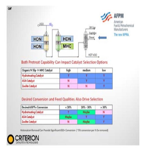
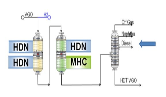
Catalyst system design considerations depend on your conversion targets, the selectivity needs for this to work in your refinery, and your existing equipment. In specifying an MHC (mild hydrocracking) catalyst system, remember that the balance of hydrotreating versus cracking catalyst and the potential addition of reactor volume are largely influenced by feed qualities and the desired level of conversion. As many of the feeds processed are high in contaminants, the pretreat section is required to ensure that a sufficient cycle life can be maintained while both meeting any product targets and minimizing nitrogen slip into the cracking section of the reactor.
HDS (hydrodesulfurization) functionality is going to remain an important criterion for some people. However, HDN (hydrodenitrification) capability is often more important as it is going to influence the cracking catalyst selection and performance due to the nitrogen slip, which really is going to end up dictating the type of long-term conversion benefits that will occur during the operational cycle.
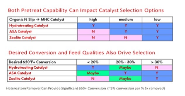
You can look at a lot of different catalyst systems, such as those outlined on the slides. Zeolite-containing products provide the highest level of conversion but tend to be more sensitive to the nitrogen slip, which can limit their long-term cycle performance. You can go to amorphous silica-alumina (ASA), which has more nitrogen capability and tolerance, but which tends to achieve a lower level of conversion. Also, if you have units with very high levels of nitrogen in the feed or relatively low capability for HDN performance, then you can actually consider using conventional hydrotreating catalyst and just operating in a mild hydrocracking mode of operation. This mode will give you lower conversion; however, for a lot of units, it can still provide significant benefits.
Once the facility economics are confirmed and the conceptual scope of the revamp has been determined, the detailed unit design considerations will need to ensure the safe, effective, and reliable long-term operation of the unit.
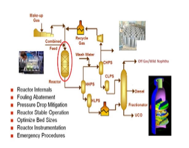
Although operation using only the existing reactor volume offers a capital advantage, it can also have technical and economic considerations. The relevance of these constraints varies from refinery to refinery; therefore, careful technical and economic evaluation is advised before converting the unit operation. Several design issues should be fully considered, including:
•Reactor internals capability
•Fouling abatement and pressure drop mitigation
•Reactor instrumentation and control needs
•Reactor bed sizes (are they too long?)
•HS&E procedure development.
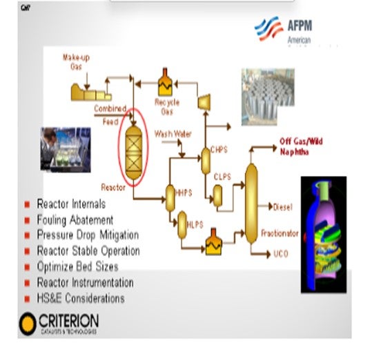
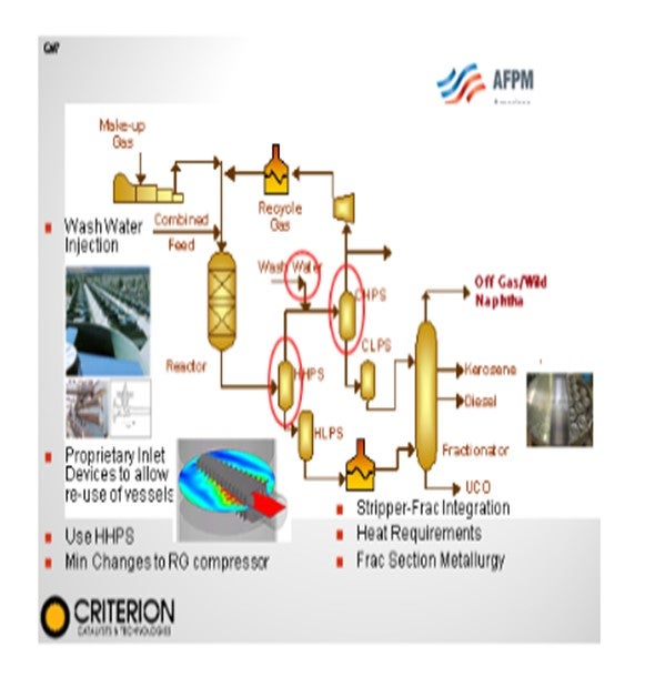
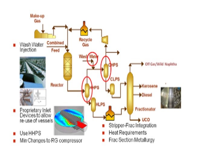
In a revamp design, significant changes to unit heat balances and flow regimes will impact the downstream recovery and fractionation section of the unit. Product separation capabilities may be a serious issue, depending on existing configuration. If a fractionation section is in place, a tower internals revamp, by itself, can often provide a low-cost solution to the increased diesel production. With this operational shift, the increased conversion will also result in more vapor traffic that needs to be accommodated in the safe operation of the unit. Final considerations also include any additional requirements for waterwash, gas treating, and metallurgy upgrades.
BODOLUS (CVR Energy)
Kevin covered a lot of these issues, particularly on the catalyst change, type, and amount. Hydrotreating catalyst alone might not give enough cracking, and hydrocracking catalyst may give too much if you just want to take that short little step from diesel production in a gas oil mild hydrocracking. Of course, as hydrocracking increases, the reactor dynamics change again. You need better temperature management. You may need to supply more hydrogen, if not a lot more hydrogen, and you must manage that hydrogen for both consumption and quench purposes.You have to be able to handle the product light ends, as well as heavier ends. Remember, if that product is a diesel product coming out of a mild hydrocracker, then you have to be careful about meeting your specifications for ULSD and/or cold flow properties.
In general, my recommendation is to involve the catalyst vendors, and that is plural. I suggest you go to multiple vendors. They do not always like a three- or four-way horse race, but it often provides you with a little more of an idea of where you might be.
Economics to consider, as mentioned, are a hydrocracker and an FCC, kind of two pumps for the same well. You have to be careful about the competitive economics with the FCC as you encourage more mild hydrocracking. Also, consider rationalizing the naphtha production because of hydrogen supply as a result of that naphtha production.
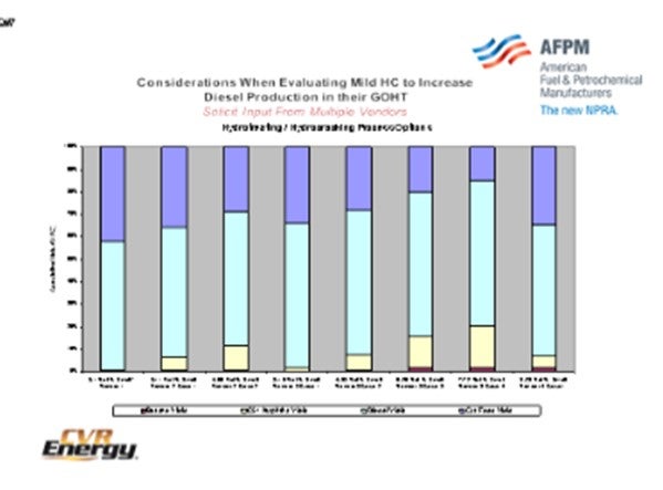
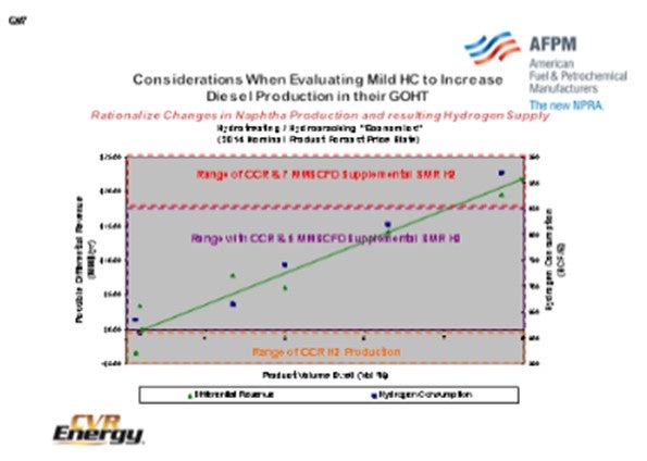
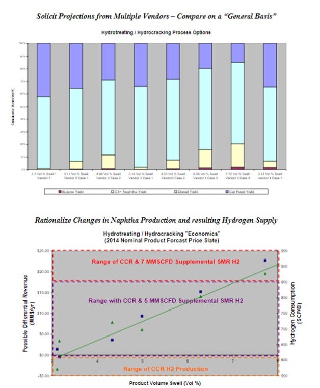
I want to briefly go through some of a case study. This slide contains a collection of data that we obtained from four catalyst vendors on different yield slates for a particular mix that we were considering. This was early on in the project. To get started, we narrowed it down, normalizing the data, and put together a single-range graph to frame up the options on the first round. As you go up in volume swell on your product, you make more potential revenue. This is net revenue on the refinery after taking most things into consideration over the cat as well. Of course, as you climb up this money line with more hydrogen consumption, as shown on the right-hand side, you can get an idea where you are.
The boxes are other ranging variables that we know we can get to this part with the current production of CCR, in terms of hydrogen. The next box up is where we might have to bring in perhaps as much as 5 million scf (standard cubic feet) of supplemental hydrogen from an SMR (steam methane reformer). And then in order to cover the top end of our range, we wanted to make sure we knew the liability of importing hydrogen from an SMR. So the buzz phrase for this: Know the size and price early so you can figure out your economics and determine what will really pay out for mild hydrocracking.
UNIDENTIFIED SPEAKER
Do any of the panelists have experience with anyone trying to do mild hydrocracking in a ULSD unit, say, to adjust T90?
CARLSON (Criterion Catalysts & Technologies)
We have done a number of designs, and we have units in operation in which we have a mild hydrocracking component in the back bed either for controlling endpoint or, as you will hear in some of the other responses, for some other benefits, for example, cold flow.
UNIDENTIFIED SPEAKER
Do you have to maintain a treat gas hydrogen availability constraint to do that?
CARLSON (Criterion Catalysts & Technologies)
It is going to depend on the operating pressure of the unit and the space velocity. If adding a mild hydrocracking component, we confirm that there is enough treat gas to not only minimize deactivation rates but also to quench that bottom bed when the conversion is not desired. This verification can provide the ability to adjust conversion levels for seasonality or market needs. Total treat gas availability can be higher in order to meet this flexibility. The minimum is typically going to be around 4:1; but again, a more detailed review is always required.
LEICHTY (Chevron USA, Inc.)
It also depends on the feedstocks being processed. If your feed is 100% straight run, then you may be able to get by with three times the chemical consumption for your treat gas ratio. The ultimate determining factor is the reactor outlet partial pressure and fouling rate at that pressure. Without any specific data, a four-to-one ratio would be fairly conservative.
UNIDENTIFIED SPEAKER I am talking about the pooled amount of hydrocracking. Do you think 3:1 would be okay?
LEICHTY (Chevron USA, Inc.)
It could be sufficient; but again, it really boils down to the catalyst fouling rate at the outlet hydrogen partial pressure.
JEFF JOHNS (Chevron Products Company)
I am interested in the commercial experience. How low do you have to get the nitrogen slip to get a reasonable amount of conversion – say, more than 10% to 15% – in a mild hydrocracking unit?
CARLSON (Criterion Catalysts & Technologies)
We have done reviews where, as you saw, it depends on your catalyst system. We have units running in excess of 400 ppm (parts per million) or 500 ppm nitrogen into the cracking section of the reactor, which might not be a cracking section where you want to put in zeolite catalyst. So you can either utilize a catalyst system with conventional alumina or use ASAcatalyst systems. And if you look at the cycle economics, you might have to evaluate it based on your projected yield shift from start-of-run to end-of-run. You will get better performance early on, and you might end up at an end-of-run performance that did not result in a big benefit from that cracking bed. However, the overall cycle economics can be favorable. If you really want to put in high zeolite catalyst and be pushing the conversion up to the 25% to 35%, then you musthave the pretreat capability of getting the nitrogen down sub-100 ppm. We have a couple of papers on the web where you can see some case studies.
SERGIO PIMENTEL (CITGO Petroleum Corporation)
In ULSD units with no specific cracking bed, what is your experience trying to adjust the cold properties, like pour point adjusting severity?OHMES (KBC Advanced Technologies, Inc.)From what we have seen, you really do not have a big impact. In fact, if you look at the cold flow profile of the components from feed to product, it is basically the same. You just happen to crack away some of the very heavy components. So yes, if you want to crank up severity and over-treat, getting a little backend destruction will slightly improve cold properties. But normally, you are only going to get about 5°F, 10°F, or 15°F distillation shift on most units without having some kind of cracking catalyst. You really will not see a big impact, maybe just a couple of degrees of pour point or cloud point.
CARLSON (Criterion Catalysts & Technologies)
That actually ties into our next question.
UNIDENTIFIED SPEAKER
We operate our hydrocrackers with 95% conversion with 5% bleed fed to FCC unit. This 5% bleed is purely for PNA (polynuclear aromatics) management. Is there a more effective way to have a better PNA management to increase the conversion in terms of advancements in engineering within the fractionator, guard bed, or clear beds? Is there a way to increase the conversion and reduce the bleed?
OHMES (KBC Advanced Technologies, Inc.)
I think we will answer your question on that a little bit later.
LEICHTY (Chevron USA, Inc.)
You have to be able to control the PNAs in order to avoid fouling in the second-stage effluent coolers and catalyst with a recycle operation. I am not aware of any ways to do that other than to bleed, so that is what we monitor and optimize.
CARLSON (Criterion Catalysts & Technologies)
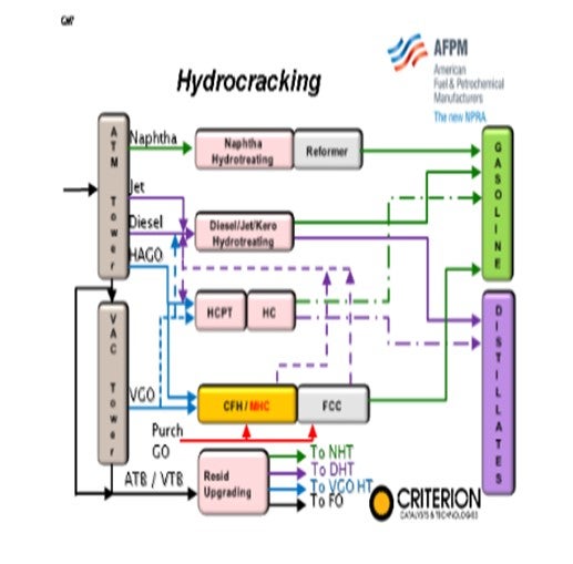
With a continued trend and long-term forecast of strengthening distillate margins many refiners look to ways of maximizing their facilities ULSD production. One area of focus is the FCC pretreat/FCC complex that typically has been designed and optimized to maximize the conversion of 650+ material into the gasoline pool, typically with a minimization of production and recovery of distillate boiling range material.
Looking at existing FCC PT (FCC pretreat)/FCC complexes, the pretreat unit objectives have tended to change over the past decade with the move to clean fuels production. In the past, the FCC PT units overall value proposition has been a combination of environmental compliance via sulfur removal and increased FCC yields. During the period of 500 ppm sulfur diesel and 300 ppm sulfur gasoline production, the pretreat objectives often were set to produce either a side-draw blendable low-sulfur diesel stream or resultant on-spec FCC naphtha product or both, with the bonus being improved FCC yields via aromatic saturation and nitrogen removal. The extent of FCC yield improvements often were a function of desired operational cycle life and available hydrogen for the pretreat units. Hydroprocessing catalyst systems were developed utilizing cobalt molybdenum (CoMo) and nickel molybdenum (NiMo), depending on these objectives and constraints.
In today’s clean fuel operations, much investment has been made in ULSD and FCC naphtha HDS with few refiners now achieving environmental compliance via previously designed pretreat units. An additional result of the global drive towards clean fuels is the continued advances in catalyst technology that have provided significant gains in both HDS and HDN performance. These technology gains are being utilized to drive new FCC pretreat designs to very high levels of performance and have provided refiners the option of revisiting how best to maximize the value of existing FCC pretreat units.
This has resulted in many units shifting catalyst system designs in order to provide higher levels of nitrogen removal and aromatic saturation by using more high activity NiMo catalysts, resulting in maximizing FCC conversion capability. If distillate maximization is desired, many FCC pretreat units can be revamped to effectively operate in an MHC mode of operation. This more severe operation is performed with higher reactor temperatures and often by modifying the catalyst system to include a more active conversion catalyst such as an amorphous silica-alumina (ASA) or zeolite.
In considering mild hydrocracking operations for VGO hydrotreating, a comprehensive facility constraint and capability review is vital to ensure that the project scope provides both the desired yield based economic return, as well as the longer-term objectives of reliability and operational flexibility to respond to market changes.
What is VGO MHC? VGO MHC typically refers to a mode of operations and catalysts system design intermediate to the severity of a conventional FCC pretreat unit and a high conversion (~65+%) hydrocracker. They typically serve two purposes: both improving FCC feed quality, as well as increasing distillate production.
It can be a low-cost alternative for difficult feeds and heavy oil conversion.
•Typically 1000 to 1500+ psig pressure
•Conversion levels usually between 20% and 60%
•Simplified process design
•Selective hydrogen consumption
•Excellent FCC feed quality
•Existing VGO units successfully revamped
•Unique configurations for cases where high quality distillates required
For grassroots designs, the project scope can actually be more clearly defined as you are starting with an empty plot space; however, with revamps of existing VGO hydrotreaters, significant considerations exist as this is usually not a catalytic drop-in solution.
Focusing on revamps of existing units, the first consideration is how will the projected MHC mode impact existing refinery configuration and downstream operations and what revamp scope will be required to provide the desired performance. Increased hydrogen demands, reduction of FCC VGO feed, and product quality targets need to be evaluated to ensure facility-wide economics support the proposed project. FCC conversion benefits require that in most cases feeds are available to maintain FCC capacity. Often, optimized FCC PT operation and improved product recovery, by itself, can provide significant gains with minimal costs.
Determining the optimal targeted operation and process scope requires an evaluation of catalyst system designs with their predicted yields slates and cycle life estimates, all of which are largely dependent on the individual design and configuration, feed types, and contaminant level, as well as the scope of the proposed revamp.
Depending on the conversion and distillate selectivity required, all alumina, alumina/ASA, or alumina/zeolite stacked systems can be considered. Higher conversions can be achieved by alumina/ASA stacks and even higher by alumina/zeolite stacks compared to total alumina system. In specifying an MHC catalyst system, the balance of hydrotreating versus cracking catalyst and the potential addition of reactor volume is largely influenced by feed qualities and desired level of conversion. As many of the feeds processed are high in contaminant metals, sulfur, and nitrogen, the pretreat section is required to remove these contaminates to ensure a sufficient cycle life can be maintained while both meeting any product targets and minimizing nitrogen slip into the cracking section of the reactor. Feed quality, reactor and catalyst system specified determine the ultimate S and N removal capability for a given cycle life; HDS functionality can remain an important criterion for some MHC units depending on existing product specifications that are dependent on-site refinery constraints and capabilities; however, HDN capability often is more important as it influences the cracking catalyst selection and performance due to remaining nitrogen heteroatoms, reducing cracking reactions. As mentioned, zeolite-containing products can provide highest ultimate levels of conversion; however, they tend to be the most sensitive to nitrogen slip, reducing their long-term effectiveness in such cases. Amorphous silica-alumina cracking catalysts provide increased levels of nitrogen tolerance with a lower level of conversion capability, and for units with limited HDN capability conventional pretreat catalyst, can be operated in a MHC mode, however, with a reduced conversion capability.
Once the facility economics are confirmed and the conceptual scope of the revamp has been determined, the detailed unit design considerations need to ensure the safe, effective, and reliable long-term operation of the unit.
Although operation in the mild hydrocracking mode using only the existing reactor volume offers many potential advantages, it can also have technical and economic constraints. The relevance of these varies from refinery to refinery and a careful technical and economic evaluation is needed before converting the unit operation. Several Issues should be fully considered:
•Conversion of VGO streams may leave the FCC underutilized, unless there is additional FCC feed available (e.g., from imports or there is additional FCC pretreat capacity e.g., due to de-bottlenecking)
•Additional hydrogen should be available as unit expansion and/or higher conversion will require more hydrogen consumption.
•The mild hydrocracking operation will result in additional naphtha that may need additional processing
•Seasonal demand factors may lead to operation for gasoline in summer and middle distillate in winter so that the advantage can only be realized for a part of the year.
The FCC pretreat unit will have shorter cycles operating in the MHC mode. Typically cycles are halved (although this depends on the feed, operating conditions and conversion target).
In a revamp design due to the changing in operating conditions, yields and reactor catalyst system design, significant changes to unit heat balances and flow regimes will impact the downstream recovery and fractionation section of the unit.
Product separation capabilities may be a serious issue depending on existing configuration; in case that a fractionation section is in place the tower internals discussed earlier can provide a low-cost solution to the increased diesel production.
•The increased conversion will result in more vapor traffic that needs to be accommodated for safe operation of the unit.
•Additional requirements for waterwash, gas treating, fractionation section equipment constraints need to be reviewed and addressed.
Key to MHC success is this full consideration and review of unit capabilities, constraints and refinery benefit combined with a unit specific catalysts system designed for balancing pretreat and cracking activity optimizing facility value.
BODOLUS (CVR Energy)
Simply increasing severity in a gas oil hydrotreater will not produce the desired selectivity to diesel products. It is preferred that some fraction of the hydrotreating catalyst be changed out. Catalyst vendors can assist in selecting the specific hydrocracking catalyst, but a catalyst change is just one of the many things to consider. Temperature and hydrogen supply management within the reactor need to be considered as the reaction chemistry moves from hydrotreating to hydrocracking. Quench flows and internal metallurgical limits need to be carefully evaluated.
The fractionator will need to be evaluated to determine if it can handle and produce the desired diesel cut. Note that making the distillation range in the fractionator does not guarantee that the product will meet all other specifications of ultra-low sulfur, cetane or cold flow properties. Post-treat or a “polishing” step may be needed to reach sulfur targets.
As with all other refinery slate changes, overall economic considerations include the impact that increased diesel/reduced gas oil/increased hydrogen consumption has on the facility.
Evaluation Program:
•Involve catalyst vender(s) in yield criteria and validate with economics.
•Solicit projections from multiple vendors and compare on a “general basis”
.•Economics need to consider hydrocracker competing with FCC unit. •Rationalize changes in naphtha production and resulting hydrogen supply.See the following slides.
SUBHASH SINGHAL (Kuwait National Petroleum Company)
The right choice of a catalyst makes the difference in achieving max diesel yield. Once we rightly define our objective while procuring the catalyst, the catalyst suppliers can offer the right mix of catalyst to achieve the refiner’s objective. If the refiner has a highly active catalyst that is suited for jet/naphtha production, even reducing the catalyst temperature does not help much.
STEFANO MELIS (Albemarle Corporation)
A common way to increase diesel production is to increase the operating severity of an existing VGO hydrotreater. Conversion in the unit is mainly thermal, but catalyst changes can increase the relative contribution of catalytic cracking if the unit is capable. Operating a VGO hydrotreater in MHC mode yields a moderate conversion increase of typically 5% to 15% over the course of a cycle, depending on unit pressure. Almost all of the converted product falls in the diesel boiling range and an improvement in bottoms quality (in particular S and N content) is also realized, however, at the cost of additional hydrogen and a significant reduction in unit cycle length.
Technical feasibility of such solution is often limited by associated processing equipment. Sufficiently high compressor capacity, hydrogen availability and quench capability are important. Downstream fractionator design is also critical to ensure the increased diesel make can be fully captured.
Even more critical is the economic evaluation. The value of the extra diesel produced is offset by a reduction in cycle length, in some cases halved compared to normal operation, with corresponding additional downtime, production loss and catalyst cost. The consequences of reduced bottoms production must also be evaluated as it typically reduces throughput to the FCCU. Finally, the effect of improved bottoms quality should be evaluated, as a significant improvement in FCCU operation and product quality is anticipated; in particular, higher FCC conversion associated with lower feed N content and improved product quality due to lower S content in all FCC products.
ROBERT WADE and CHARLES OLESEN (Advanced Refining Technologies, Worms, Germany)
There are a number of considerations when designing a catalyst system for mild hydrocracking service. This mode of operation tends to have higher fouling rates than conventional high pressure hydrocracking (HCU) service, and also has two competing constraints compared to a single constraint for the typical high pressure service. In a mild hydrocracking operation, cracking conversion is controlling at SOR; and as the hydrotreating (HDT) catalyst deactivates through the run, the HDS and HDN conversion will start to become controlling. This means it is critical to understand how the H2 partial pressure varies throughout the run and the impact this has on the expected fouling rate of both the HDT and HCU catalysts. In addition, it is important to having a good understanding of the nitrogen slip to the HCU catalyst so that the activity of the HCU catalyst is properly balanced against desired selectivity.
The addition of HCU catalyst to an existing hydrotreater will come at the cost of decreased HDS/HDN catalyst volume. This will reduce the activity and life of the HDT section. The HCU catalyst does have some level of HDT activity, but not enough to overcome the decreased volume of HDT catalyst. Figure 1 below summarizes pilot plant data which demonstrates how the HDS activity of the catalyst system is impacted by the addition of HCU catalyst. The addition of a small amount of HCU catalyst has little or no impact on HDS activity, but higher volumes of HCU catalyst result in decreasing HDS activity.
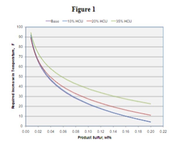
The changes in HDT activity need to be balanced against the cracking activity of the catalyst system as shown in Figure 2 below. Not surprisingly, increasing the amount of HCU catalyst results in higher levels of conversion.
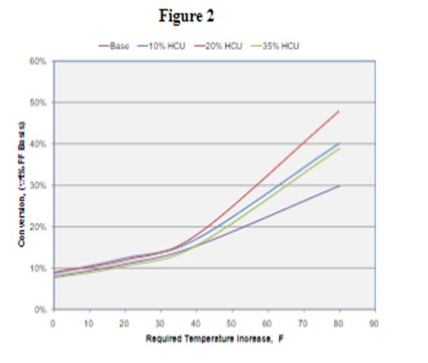
Achieving the proper balance of HDS/HDN activity and cracking activity is a challenge and the system is best customized on a case by case basis. The volume and type of HCU catalyst needs careful consideration in order to provide the desired conversion and minimize production of excess gas and naphtha. This is especially important as the cycle progresses and the reactor temperatures approach EOR.
A mild hydrocracking system will make more light products so the product recovery section needs to be evaluated to ensure it can handle the increase in lighter products. In addition, there will be an increase H2 consumption and corresponding increase in heat release (higher exotherms). Consideration needs to be given to make up H2 requirements and temperature control scheme to make sure they are adequate for the expected changes.

