


Question 8: How do you improve cold flow properties in a hydrocracker?
LEICHTY (Chevron USA, Inc.)
I will discuss several considerations including crude and product PNA distribution, feed effects, distillation performance, catalyst selection, and operating parameters.
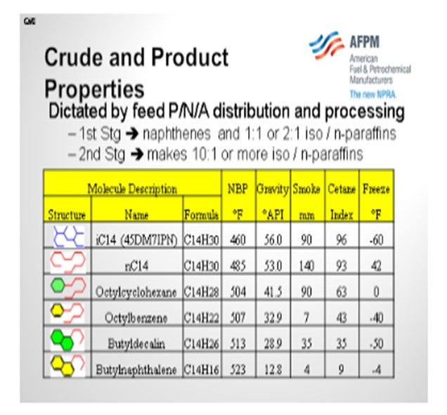
If you take a look at the molecular structure and properties of hydrocarbons in the C14 series, you will notice that the n-paraffins have the worst cold flow properties. Some of the multi-ring aromatics are also not good. So, when looking at crude purchases, waxy Far East crudes or some of the new shale-derived crudes will have worse cold flow properties because there are more paraffins in the feed. Moreover, any overlap in the feed (material that boils below the recycle cutpoint) will negatively impact cold flow properties since overlap material will contain more n-paraffins than the hydrocracked products. Finally, the proportion of product generated by the first stage versus second stage will also have an impact on cold flow properties. This is because the first-stage hydrocracker product tends to be 1:1 or 2:1 isoparaffin-to-normal paraffin ratio, whereas second-stage products can make 10:1 iso-to-normal paraffin ratio or better. Obviously, the more isomerization you get, the better your properties will be.
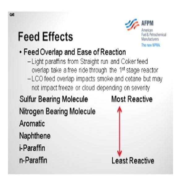
Now let’s consider feed overlap and ease of reaction. Light paraffins from straight run and coker feed, whether they boil below or above the recycle cutpoint, will tend to take a free ride through the first-stage reactor because they are the least reactive molecules and will negatively impact product cold properties. LCO feed overlap will impact the gravity, smoke, and cetane, but it may not impact the freeze or cloud, depending on the recycle cutpoint and the degree of saturation.
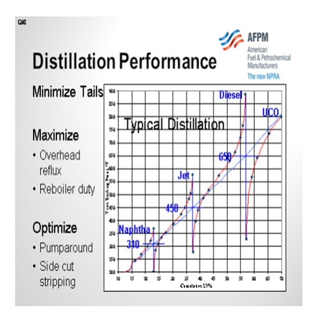
Distillation performance is probably one of the single biggest killers of cold flow properties. The cumulative distillation diagram below helps illustrate how the heavy tail of a distilled product can affect the cold properties. Cloud point and freeze point are defined by the temperature at which the first crystals of wax form in a hydrocarbon mixture as it is cooled. Sloppy distillation results in long tails which have material that will crystallize at a higher temperature. It is therefore important to have sharp distillation cuts by maximizing overhead reflux and minimizing pumparound in order to achieve high liquid-to-vapor ratio in the distillation tower. Note that it is also important to maximize reboiler duty in order to strip out the material boiling below the recycle cutpoint (the cutpoint between diesel and unconverted oil). The diagram shows approximately 5% yield that is boiling below the recycle cutpoint in the unconverted oil. With better stripping, much of this material could be recovered as on-spec diesel instead of cracked into less valuable products.
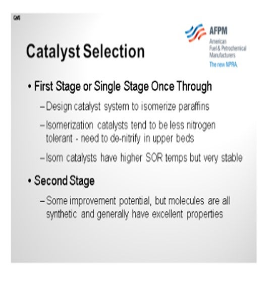
In your catalyst selection, if you have a single-stage hydrocracker, you want to design your catalyst system to isomerize paraffins to the highest degree possible. These types of hydrocracking catalysts tend to be a little less nitrogen-tolerant, so it is important to do good denitrification on the upper beds. The latest generation catalysts have higher start-of-run temperatures but have proven to be very stable over time. In the second-stage of a two-stage hydrocracker, there is not much room to improve cold properties since all of these molecules are synthetic in nature and have greater than 10:1 iso-to-normal ratio.
On this slide is a diagram showing how if you move from a conventional first-stage hydrocracking catalyst up to a newer generation that has a higher selectivity, you may require a little higher temperature in order to get the pour and cloud point reduction. The good news is that these newer generation catalysts are very stable, so you will not see a high degree of fouling over time.

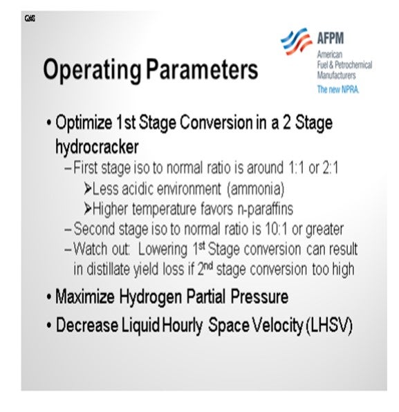
In the two-stage hydrocracker, it is important to optimize first-stage conversion. The first-stage products see a less acidic environment because of the presence of ammonia and higher temperatures. These conditions tend to favor n-paraffin production. Knowing this, it would be tempting to shift the first-stage conversion to the second stage by loading less hydrocracking catalyst in the first stage. However, in doing so, the per-pass conversion in the second stage could get so high that over-cracking will cause a reduction in distillate yield. Maximizing distillate with the desired cold flow properties therefore requires an optimization between first- and second-stage hydrocracker conversions. In any scenario, it is desirable to maximize hydrogen partial pressure and/or minimize space velocity in order to saturate diaromatics, promote cracking and isomerization, and achieve high distillate yield with good cold properties.
CARLSON (Criterion Catalysts & Technologies)
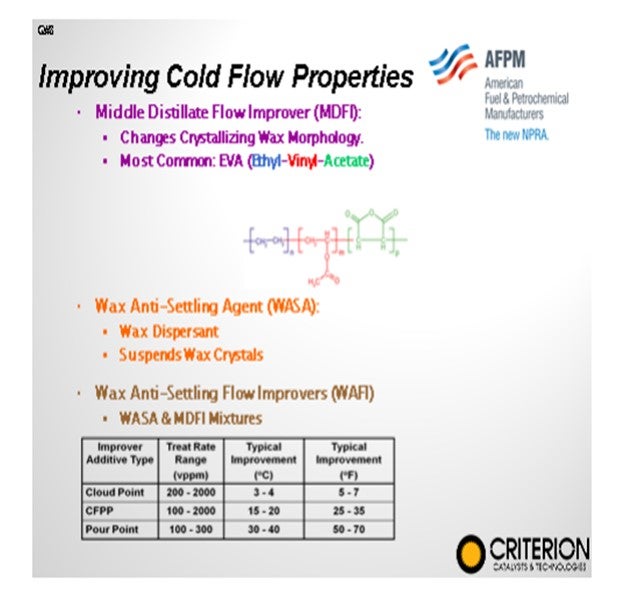
In addition to those considerations just presented, we look at middle distillate flow improvers and wax anti-settling agents. They can be effective, of course, in controlling pour point and CFPP (cold flow plugging properties), but they do not tend to help us much on cloud point. Neither of them adds to our operating cost. So, if we want to achieve significant cold flow improvement, we really need to know how to get rid of these long linear paraffins in the reactors.
To achieve a considerable improvement in cloud point, there is a need to remove the components causing the high cloud point. As discussed, reducing the feed final boiling point can reduce these components, but it can result in yield losses that may be economically unfavorable. A better approach is to install catalysts that can modify or remove the linear paraffins within the feedstock (dewax) while achieving the desired product selectivity.
Two types of reactions are used for the removal of linear paraffins: selective paraffin hydrocracking and paraffin isomerization. Cracking decreases both the melting and the boiling point, while isomerization mostly affects the melting point, leaving the boiling point largely intact. Cracking creates two smaller fragments from the original linear chain paraffin molecule that have substantially lower melting points. However, the boiling point will also shift downward, potentially moving the molecules out of the target boiling range and reducing the total diesel yield. This yield shift can occur when using conventional zeolites in hydrocracking operations.

I
somerization, as you heard, would be a preferred mechanism because it both improves the cold flow properties by lowering the melting point and it leaves the final molecule in the distillate boiling range. However, selective isomerization is difficult to do in hydrocracking applications. Selective isomerization is typically much more favorable in a clean second-stage reactor with platinum or palladium-type catalysts.
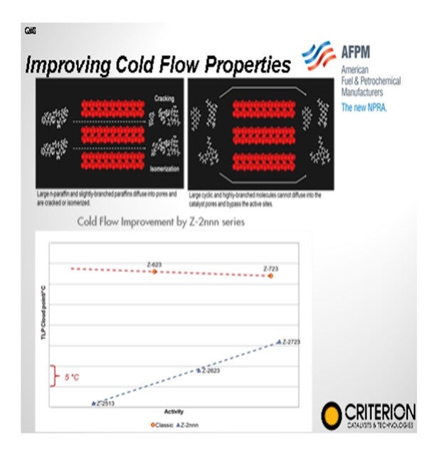
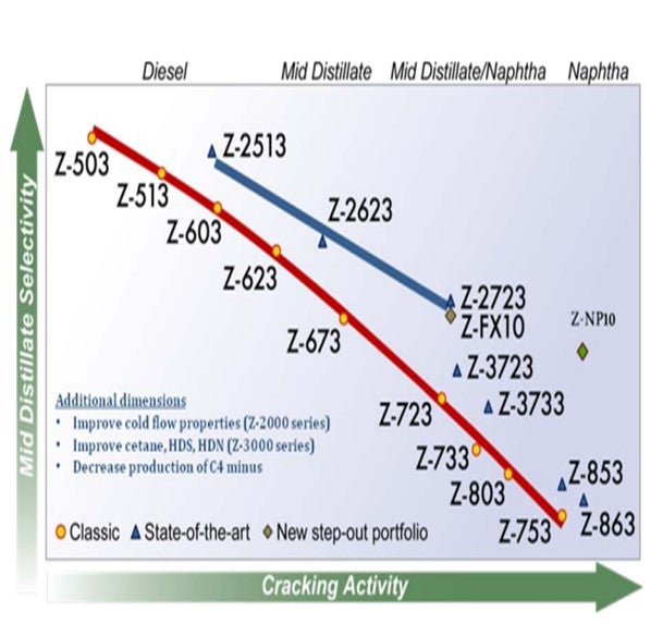
Effective dewaxing requires a proper differentiation between the linear paraffinic molecules (wax) and the rest of the feed molecules in order to achieve a high selectivity and minimize distillate yield loss. In hydrocracking, this is achieved by employing a shape-selective zeolite to preferentially convert the large linear paraffins. Criterion/Zeolyst has a portfolio of shape-selective cracking catalysts, its Z-2000 series, that selectively crack large linear paraffins resulting in an improvement in the product cloud point all along the activity/selectivity scale. These catalysts provide a boost in middle distillate yield versus conventional wide-pore zeolite catalysts due to the fact that the converted material has the tendency to reside in the distillate boiling range.
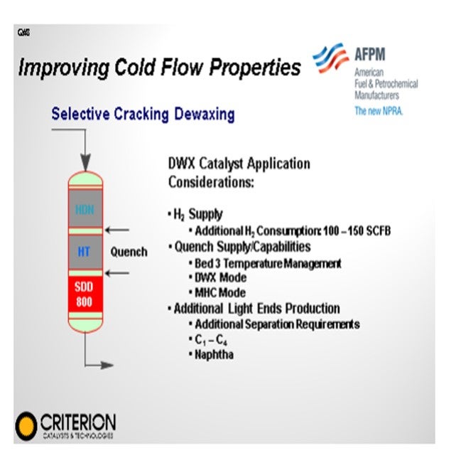
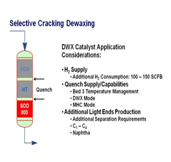
In mild hydrocracking operations, catalytic dewaxing can be employed on the backend of the upgrading process once all other properties have been already achieved. Criterion has a number of distillate feed applications where a catalyst, such as an SDD-800, can be loaded in the last bed of the reactor to assist in improving cloud point and, again, minimize distillate losses.
KEVIN CARLSON and WARD KOESTER (Criterion Catalysts & Technologies)
In the last decade, improving the cold flow properties of various feedstocks in a selective and cost-efficient way has gained increasing importance. In addition to providing a product in the specified cold flow property range, refineries apply cold flow improvement processes to avoid using cold flow additives, to reduce their kerosene blending requirements, to upgrade heavier feedstocks with higher cloud and/or pour points, and to create room in the blending pool for heavier feeds. The growing interest in cold flow improvement technologies stems from the increasingly stringent engine specifications, the processing of more paraffinic crudes, and the desire to sell the products at markets with demanding cold flow properties specifications.
There are several routes to improve the cold flow properties of distillates from a hydrocracker. Dilution by the addition of kerosene and/or cold flow improvers to the diesel pool have been the most widely applied routes. These methods are effective for pour point and cold filter plugging point (CFPP), but these have little effect on cloud point.
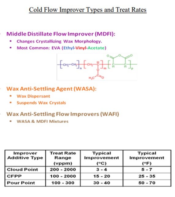
Cloud point measurement is aimed at registering the first appearance of solid particles and the additives/diluents used for improving the flow will not prevent the crystallization; rather, they delay it by modifying the shape of the crystals or by impeding their growth. Therefore, to achieve a considerable improvement in cloud point, there is a need to remove the components that cause the high cloud point. Reducing the feed final boiling point can achieve this with limited effect, but this results in relatively large yield losses that may be economically unfavorable. A better approach is to install catalysts that can modify or remove the linear paraffins within the feedstock (dewax) while achieving the desired product selectivity.
Two types of reactions are used for the removal of linear paraffins during catalytic dewaxing to improve the cold flow properties of the diesel: cracking and isomerization (selective paraffin hydrocracking and paraffin isomerization).
Cracking decreases both the melting and the boiling point, while isomerization mostly affects the melting point leaving the boiling point largely intact. Cracking creates two smaller fragments from the original linear chain paraffin molecule. These fragments have substantially lower melting point than the starting molecule and the cold flow properties, especially the cloud point, will drastically improve. However, the boiling point will also shift downward, potentially moving the molecules out of the target boiling range of the feedstock, reducing the total diesel yield. This is what can occur when using conventional zeolites in hydrocracking.
Isomerization is the preferred mechanism for converting linear paraffins because isomerized products have the same molecular weight as their parent starting molecules thus preserving yield. However, you cannot do selective isomerization under hydrocracking conditions with base metal catalysts. Selective isomerization is much more favorable in a clean second-stage environment (i.e., with very little to no H2S, NH3, unconverted organic nitrogen and sulfur-containing molecules) with employment of noble metals such as Pt (platinum) or Pd (palladium).

Effective dewaxing requires a proper differentiation between the linear paraffinic molecules (wax) and the rest of the feed molecules in order to achieve a high selectivity and to minimize distillate yield loss.
In hydrocracking, this can be achieved by employing a shape selective zeolite as the active acidic component to preferentially convert large linear paraffins. Criterion/Zeolyst has a Z-2000 series of shape selective cracking catalysts that selectively crack large linear paraffins resulting in an improvement in the product cloud point all along the activity/selectivity scale. These catalysts provide a boost in middle distillate yield versus conventional wide-pore zeolite catalysts due to the fact that the converted material has the tendency to remain in the distillate boiling range.
In mild hydrocracking applications, catalytic dewaxing can be employed at the back end of the upgrading process, where all other properties of the product (i.e., sulfur, nitrogen, aromatic content and cetane index) have already achieved the required target levels. Criterion has a number of distillate feed applications where a dewaxing catalyst, such as Criterion’s SDD-800, is loaded in the last bed of a single stage mild hydrocracker to improve cloud point while minimizing distillate yield loss.
BODOLUS (CVR Energy)
Start with catalyst vendors for recent developments in their products and capabilities. Cold flow properties are a very complicated function of catalytic selectivity. Our refineries adjust cold flow properties seasonally at the crude unit via distillation specifications and monitoring run-down tank samples. No daily or seasonal adjustments are made to the hydrotreaters/hydrocrackers for cold flow parameters. Once the catalyst selection is made, the hydrotreating and fractionation is done to accommodate distillation, flash and sulfur targets. A point worth mentioning in our system is the rationalization of the economic interactions between competitive distillate products in the finished product pool. The desire to produce high margin seasonal products (#1 kero) or solvents (mineral spirits) often impact or overly constrain the diesel cold flow properties adjustments made at the crude units.
SUBHASH SINGHAL (Kuwait National Petroleum Company)
The easiest way to achieve better cloud point/CFPP could be to adjust fractionator operations to drop some heavy kerosene to diesel inside the column (within flashpoint specs limits).
Year
2012
Process
Question 9: What do the possible causes of high pressure drop in lower beds of HT (hydrotreater) and HC (hydrocracker) units? What techniques are used to diagnose the causes prior to shut down? Are there any mitigation techniques or strategies to extend the cycle?
LEICHTY (Chevron USA, Inc.)
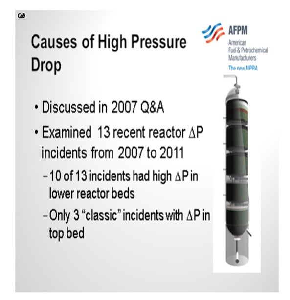
The topic of the causes of high-pressure drop was discussed in the 2007 Q&A, so you may want to refer to that transcript for additional information. At Chevron, we had a string of 13 reactor ΔP (pressure differential) incidents between 2007 and 2011. Ten of these occurred in lower reactor beds with only three of them being classic top bed ΔP incidents.
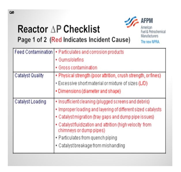
The root causes are listed in a table included with my Answer Book response. To save time, I am not going to go through each one in detail. There are a wide variety of causes for these incidents; and in some cases, multiple causes. This list shows you that there is no easy fix that will solve all of the issues. Rather, there are many steps that must be done with excellence in order to avoid ΔP issues, especially in the planning and execution of turnarounds. A checklist was developed in order to methodically approach and analyze each incident. It was also used to devise action plans to avoid future incidents. In all of our incidents, it was impossible to determine the exact root cause until the reactor was opened and inspected. Basically, we were surprised every time.

Fortunately, we have had good crime scene investigation capability that has allowed us to generate this checklist of possibilities. When performing any incident investigation, it is important to think about all of the possible causes. The following slide summarize our findings. The causes highlighted in red are ones that were actual root causes of an incident. Among them are classic feed contamination in the upper beds, catalyst quality issues with strength, and loading catalyst of the wrong dimensions. The process of catalyst loading is also critical. In the table below, we found four different root causes attributed to catalyst loading. Making sure that the catalyst loaders are properly trained and supervised is critical.
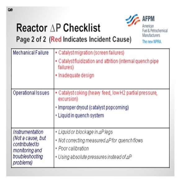
We have also seen mechanical failures in the reactors cause excessive pressure drop. In one case, a screen failure resulted in catalyst migration into the reactor internals. In another case, a quench pipe developed a leak, which then pulverized the surrounding catalyst to a powder.
Operational issues, such as loss of recycle, have been observed as a culprit of increased ΔP. We have also listed instrumentation as a category, even though it is not really a root cause, because it is critical to validate pressure drop issues and predict the point in time when the maximum allowable pressure drop will be reached.
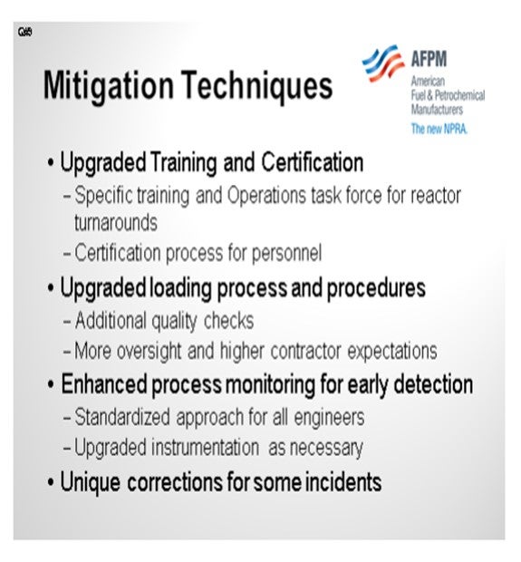
So, what did we do to mitigate this plague? We upgraded our training and certification program for operators. We now have an Operations Task Force for reactor turnarounds. This task force works with multiple hydroprocessing units across all refineries to help ensure successful turnarounds and prevent ΔP issues. There is a rigorous certification process the operators must complete to become part of the task force. Responsibilities include additional quality checks when loading, more oversight, and higher contractor expectations. We also have enhanced process monitoring for early detection, and we have standardized the approach of how all process engineers monitor for ΔP. In addition, we have upgraded instruments as necessary and made additional unique corrections.
BODOLUS (CVR Energy)
Steve gave a lot of examples. But historically, my key suspect for middle bed pressure drop is the precipitation phenomenon; that is, something dropping out as you go through the reaction profile. It brings to mind the old phrase a P-Chem (Physical Chemistry) professor used to tell us, “You know, if you are not part of the solution, you are part of the precipitant.” So as far as DP and middle beds, I always look for what might be dropping out of the solution, which could be the traditional carbon laydown if your gas-to-oil ratio is not good enough. Or in recent years, I have seen a lot of the asphaltene precipitant in middle beds that occurs as a result, again, of the destruction of the solvating compounds around the asphaltenes. They are often called maltenes.
Another key precipitation mechanism is the formation of the iron sulfides. As iron species come in with your feed, they may be part of corrosion products. They come in and may be in oxide form or part of water being brought in. But as you go through the water dew point, that iron has nowhere to go. And as you build up H2S down through the reactor profile, you have a tendency to want to form iron sulfides. Now once the iron sulfides form, they want to know where other iron sulfides are so they can hook up and precipitate; and before you know it, you have some crystals growing in the middle bed. These crystals will typically be iron sulfides.
Now I will address diagnosis, monitoring, and mitigation. Again, the mitigation is dependent upon the diagnosis of a true cause. Monitor each bed as a percentage of the overall reactor train DP. So if you are fortunate enough to have DP right across every bed, then each bed will have a percentage of the total ∆P, which normalizes out changes in gas-to-oil ratio and flow. Also, design the catalyst bed for a particular pour size, void volume, and inactivity profile, again, coming back to stacking the beds in your favor. There was an occasion where suspected precipitation in the reactor was not necessarily growing on the catalyst particles themselves like a carbon. In that case, we had good luck washing iron sulfides out with a low-temperature hydrocarbon flush. This flush can be done as a last-ditch resort when you find your DP building. The proof of that was in downstream coalescers and things like that that we would find. They became clogged when we did the flush with the oil, and analysis of that material showed it to be iron sulfides.
BODOLUS (CVR Energy)
High pressure drops in the second and/or subsequent beds of hydrotreaters may be an indication of incipient carbon laydown or other material precipitation. Excessive carbon laydown can result when hydrogen-to-oil ratios are outside required limits in successive beds. In some cases, contaminants can be introduced via quench streams adding to intra-bed pressure drop.
Precipitation of material other than carbon can occur depending on reactor conditions and feedstocks. Precipitants can include clays and minerals, most often from heavier Bitumen-derived feedstocks. For heavy feeds containing Asphaltenes, severe hydrotreating of the bulk liquid may cause precipitation of the Asphaltenes as solubility of these compounds are decreased with increasing conversion of the solvating compounds (maltenes). Other possible precipitants are fine iron sulfide particles that are produced as the degree of desulfurization produces higher hydrogen sulfide partial pressures down through the bed.
Monitoring pressure drop in all beds need to be looked at. A preferred technique is to set a base line that tracks the percentage of pressure drop through each bed versus total reactor pressure drop. This provides a simple way to “normalize” pressure drop for feed rate changes.
Mitigation efforts start with feed filtration to get as much solid material out of the feed as possible. Nominally, an efficient 25-micron filtration element is a good place to start while building a case for short-term filtration costs versus longer term bed pressure drop build. Careful selection of reactor bed grading and catalyst size can help extend cycle life. Increasing the particle size of the active catalyst bed can allow additional solids to pass through. Pay particular attention to the void volume of the previous loading and determine what future loading may be able to increase it.
On occasion, a low temperature (300°F) hydrocarbon wash can help reduce mid-bed pressure drop by changing the gas to oil ratio and bed hydraulics.
GREG ROSINSKI and CHARLES OLESEN (Advanced Refining Technologies)
There are several causes related to a poor turnaround or poor catalyst loading. A damaged or dirty outlet collector, dirty support screens or improper size grading at the bottom of a catalyst bed can all lead to high pressure drop in a lower bed. It is important that the reactor and screens be cleaned before loading any catalyst. Proper size grading of catalyst at the bottom of each bed is also important. If the catalyst size difference between grading layers is too large, smaller diameter catalyst can migrate through subsequent layers and ultimately plug the support screens or outlet collector. It is also critical to make sure nothing (tools, hardhats, etc.) gets left in the reactor during a loading.
Pressure drop in a lower bed can also be caused by the gradual accumulation of iron sulfide or other fines. These fines have small enough particles that they can be carried through upper beds. The particulates can then drop out in a lower bed. Some synthetic crudes may have fine particulates of clay or sand which can deposit in lower beds, as discussed in our answer to Question 5.
Excessive coke formation due to hydrogen starvation from poor gas distribution or low H2/Oil ratio combined with higher temperatures has also been identified as a cause of lower bed pressure drop. It is important to keep the H2/oil ratio above a specified minimum, and if reduced H2 availability is anticipated the charge rate should be reduce or cracked stocks removed for the period to ensure the minimum H2/oil ratio is maintained.
Another cause for lower bed pressure drops which we have seen involves debris or water introduced though the quench line. Quench systems should be drained and/or exercised while the catalyst is cold to prevent sudden water vaporization and breaking of catalyst pellets.
JAN KOURI (Petroval LP)
Although it is something done immediately after shutdown, getting a good composite sample of the catalyst bed may answer questions concerning pressure drop. There is a system called “PROBACAT” that is used to collect catalyst samples from within a catalyst bed. The system is capable of sampling 30’ (feet) to 40’ into catalyst beds and collect samples every 6” (inches) to 8” as it goes down.
Year
2012
Process
Question 10: Does hydrotreated product recycle count the same as fresh virgin feed for the catalyst break-in period?
BODOLUS (CVR Energy)
Yes, recycled product is generally acceptable during the break-in; but as we have discussed earlier, perhaps not all recycled product is created equal. ULSD recycled product is going to be a lot better than an ultra low sulfur gasoline recycled product that may have the residual olefins in it. And again, synthetic crudes, if fresh virgin feed or from a synthetic crude, may or may not have residual issues associated with olefins as a result of whatever production process they went through.
Generally, a break-in period is very dependent upon the catalyst type in the intended service; so, it changes a little with each unit. To reiterate again, it is important to have a good relationship with your catalyst vendor. Ask specifically what the vendor wants to see in terms of unit start-up procedures and feed specs. You need to gravitate back to the actual specifications of the feed rather than just to a catch-all term like, “Oh, okay, it is straight run material.” Take a look at the boiling point constraints if there is an endpoint limit or measurement of olefins. You want little or no olefins in this start-up material or break-in material. During the break-in, you need to monitor bed performance and keep track of the bed ∆Ps as best you can; and if you find those going off the tracks, then implement some corrective action.
There are a wide range of catalysts and catalyst prep options available. Not only is it important to select the base catalyst you want, but you have a lot of pretreatment options. The traditional oxide form can be loaded in a regular air atmosphere, but that will take the longest time in a post-turnaround interval to get you back up and running again where you have to sulfide that catalyst, in situ. If presulfided, you can shave off a little time. Now of course, there is preactivated material as well, which has a more limited break-in period. However often, depending on the catalyst, you will still have to restrict the number of cracked stocks. Some of the pretreatment vendors now believe that they have kind of a load-and-go type of catalyst which provides some cracked stock protection during the break-in period.
The key ideas this afternoon’s Principles & Practice session is going to address are a lot of these turnaround issues; because as we all know, pressures from management to shorten the break-in period after a turnaround can be significant, crushing, demanding, whatever you would want to say. As you get towards that very end of the turnaround, everyone is tired. You see the taillights of everyone leaving the site, and the last step to do is this break-in period. Everyone wants to know why it cannot happen in a couple of hours. So there is a lot of pressure at that point in the turnaround experience. The P&P session this afternoon should be good for you all to attend to learn more about this subject.
ANDREW LAYTON (KBC Advanced Technologies, Inc.)
If it is hydrocracker start-up, remember that recycle has had the sulfur and nitrogen removed. You can run into trouble if you do not realize that the nitrogen in the total feed is dropping, which can give you a temperature runaway start-up. So to some extent, recycle is not the same as virgin feed because the nitrogen has been partly removed, which can make the hydrocracker catalyst overactive at start-up. This is not such a significant consideration for normal hydrotreating catalysts without zeolite content.
STEPHEN PERRY (Motiva Enterprises)
I am not sure if I heard it or not, so to reiterate: If you are going to use recycle during the break-in period, make sure you flush the catalyst fines out to tankage before closing the recycle loop to the feed drum.
BODOLUS (CVR Energy)
Yes, that is a good point. You want to flush the catalyst fines that first couple of hours or until you see the product run clear, yes, and then go to recycle mode. Good point.
BODOLUS (CVR Energy)
Generally, the recycled product of a hydrotreater is acceptable feed during the break-in period, but the better criteria for what to use depends on the process, the compositional details of the feed, and the catalyst type. Due to the highly active state of the catalyst during break-in, it is the exotherm generated in the bed that needs to be monitored, controlled and moderated. Key input in what feed slate and break-in period to use should be provided by the catalyst vendor as there are many specific issues involved.
The ability to use recycle material also depend on the type of hydrotreating process is involved. Recycled ULSG has appreciable residual olefins and may not be appropriate as the initial start-up material. For recycled products that may have residual exothermic activity, the catalyst vendor can provide guidelines for acceptable bed temperature limits.
Care should also be paid to determining the origin of the “fresh virgin feed”. Just because the feed was derived as straight run from crude distillation may not automatically mean that it is acceptable as a start-up feed. As various “synthetic crudes” appear on the market, it is difficult to know the previous processing history of the crude fractions. Focus should be on the specific parameters the catalyst vendor requires to assure successful start-up. Start-up feed selection criteria should be based on physical and chemical parameters such as material endpoint, olefins content or aromatics constituents. Unless otherwise specified, break-in feeds for diesel units should have and endpoint less than 700°F and very low or no measurable olefins or diolefins.
Following a catalyst change-out, total time from warm-up to on-specification can vary dramatically depending upon the catalyst type and state. Catalysts can be provided in oxide form, presulfided, preactivated, or preconditioned (for cracked feed protection). Selection of the catalyst preprocessing can shorten the break-in time, but each selection has an optimal time line and preparation costs. Working with the turnaround planners well before the change-out can help establish and communicate options and alternatives.
Pressure from refinery management to shorten conditioning period after a turnaround can be significant. Delays experienced early in the maintenance process may compress the originally envisioned start-up window. Note that specific steps that can be taken to minimize overall downtime are covered in this meeting with a Principles & Practice session.
ERJA RAUTIAINEN and STEVE MAYO (Albemarle Corporation)
When giving an answer to this question we have assumed that the break-in period is the period directly after the catalyst presulfiding has been completed and the fresh feed is taken in.
After the catalyst presulfiding has been completed it is advised not to feed cracked stock during the first three days of operation. Hydrotreated product would meet this requirement; however, there are other concerns using hydrotreated product for catalyst break-in. One problem is the typically low sulfur content of the material. A minimum amount of H2S is needed to ensure complete sulfidation is maintained on a freshly sulfided catalyst. Too low H2S partial pressure may cause metal sulfides to transform into an inactive metal state, which is very difficult to transform back to a sulfide. This problem could be overcome by injection of a sulfur (S) spiking agent, such as DMDS, to the feed. The exact amount of sulfur required can be calculated with the help of phase diagrams, but we typically use between 25 ppm and 50 ppm S in the feed.
Another, more difficult to overcome, issue is the lack of coke forming components in a hydrotreated feedstock. While it is desirable to avoid the introduction of high concentrations of coke precursors, de-edging of the hyperactivity of freshly sulfided catalyst necessitates a controlled deposition of coke. Break-in with a hydrotreated product will less easily accomplish the required de-edging of catalyst activity and leave the catalyst susceptible to rapid coke deposition when cracked feedstock is added. The recommended a three-day break-in before cracked feed addition is ineffective because so little activity de-edging will occur with hydrotreated feedstock. If fresh virgin feedstock is not available for the break-in period one solution is to blend a small amount of cracked feedstock with the recirculating hydrotreated product. While not a recommended solution, it may be superior to alternatives for de-edging catalyst activity during the break-in period.
MEREDITH LANSDOWN and BRIAN WATKINS (Advanced Refining Technologies)
Hydrotreated product recycle can be supplemented for feed during the catalyst break-in period after sulfiding; however, there are several issues that need to be considered when doing so. The initial break-in period is designed so that the catalyst does not see elevated initial temperatures along with materials that could prematurely place a high level of coke down on the catalyst surface. This allows the hyperactive sites on the catalyst that are present just after sulfiding to be tempered in order to prevent this. Use of product recycle has the advantage that the material will be very low in coke precursors present in other stocks which will help prevent rapid coke laydown. It also has the advantage that if this is done to supplement a shortfall in total feed to the unit due to a limited quantity of available straight run stocks, the unit can be maintained at maximum rates, ensuring that good distribution is maintained and minimizing premature fouling.
The downfall would be if product recycle is the sole source of feed to the unit, then over a short period of time, all of the sulfur will be removed from the feed. This will increase the hydrogen partial pressure at the catalyst surface and could begin to reduce the active metals if H2S presence is not maintained to keep the catalyst sulfided. In this case it is recommended that minimum H2S levels on the order of 5000 wppm (weight parts per million) are maintained in order to keep the catalyst sulfided. It is also recommended that temperatures no higher than the final sulfiding temperature be used to also minimize any possible reduction or premature coking.
Year
2012
Process