Question 9: What do the possible causes of high pressure drop in lower beds of HT (hydrotreater) and HC (hydrocracker) units? What techniques are used to diagnose the causes prior to shut down? Are there any mitigation techniques or strategies to extend the cycle?
LEICHTY (Chevron USA, Inc.)
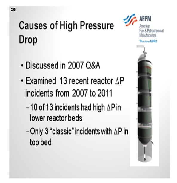
The topic of the causes of high-pressure drop was discussed in the 2007 Q&A, so you may want to refer to that transcript for additional information. At Chevron, we had a string of 13 reactor ΔP (pressure differential) incidents between 2007 and 2011. Ten of these occurred in lower reactor beds with only three of them being classic top bed ΔP incidents.
The root causes are listed in a table included with my Answer Book response. To save time, I am not going to go through each one in detail. There are a wide variety of causes for these incidents; and in some cases, multiple causes. This list shows you that there is no easy fix that will solve all of the issues. Rather, there are many steps that must be done with excellence in order to avoid ΔP issues, especially in the planning and execution of turnarounds. A checklist was developed in order to methodically approach and analyze each incident. It was also used to devise action plans to avoid future incidents. In all of our incidents, it was impossible to determine the exact root cause until the reactor was opened and inspected. Basically, we were surprised every time.

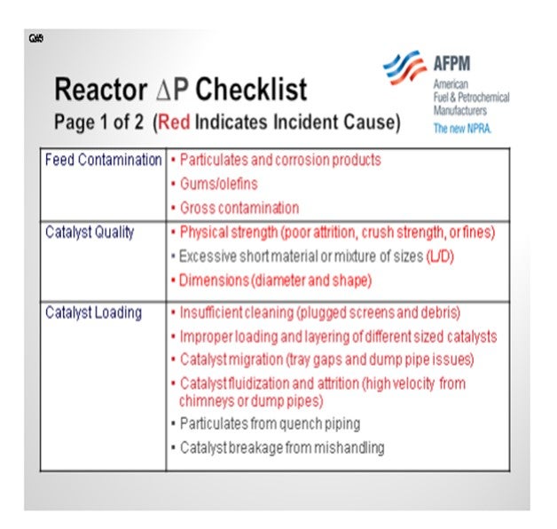
Fortunately, we have had good crime scene investigation capability that has allowed us to generate this checklist of possibilities. When performing any incident investigation, it is important to think about all of the possible causes. The following slide summarize our findings. The causes highlighted in red are ones that were actual root causes of an incident. Among them are classic feed contamination in the upper beds, catalyst quality issues with strength, and loading catalyst of the wrong dimensions. The process of catalyst loading is also critical. In the table below, we found four different root causes attributed to catalyst loading. Making sure that the catalyst loaders are properly trained and supervised is critical.
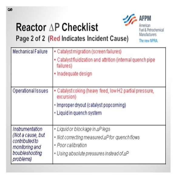
We have also seen mechanical failures in the reactors cause excessive pressure drop. In one case, a screen failure resulted in catalyst migration into the reactor internals. In another case, a quench pipe developed a leak, which then pulverized the surrounding catalyst to a powder.
Operational issues, such as loss of recycle, have been observed as a culprit of increased ΔP. We have also listed instrumentation as a category, even though it is not really a root cause, because it is critical to validate pressure drop issues and predict the point in time when the maximum allowable pressure drop will be reached.
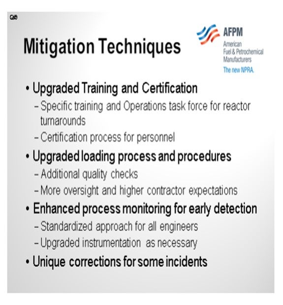
So, what did we do to mitigate this plague? We upgraded our training and certification program for operators. We now have an Operations Task Force for reactor turnarounds. This task force works with multiple hydroprocessing units across all refineries to help ensure successful turnarounds and prevent ΔP issues. There is a rigorous certification process the operators must complete to become part of the task force. Responsibilities include additional quality checks when loading, more oversight, and higher contractor expectations. We also have enhanced process monitoring for early detection, and we have standardized the approach of how all process engineers monitor for ΔP. In addition, we have upgraded instruments as necessary and made additional unique corrections.
BODOLUS (CVR Energy)
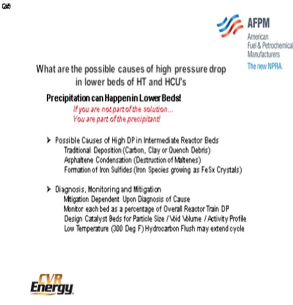
Steve gave a lot of examples. But historically, my key suspect for middle bed pressure drop is the precipitation phenomenon; that is, something dropping out as you go through the reaction profile. It brings to mind the old phrase a P-Chem (Physical Chemistry) professor used to tell us, “You know, if you are not part of the solution, you are part of the precipitant.” So as far as DP and middle beds, I always look for what might be dropping out of the solution, which could be the traditional carbon laydown if your gas-to-oil ratio is not good enough. Or in recent years, I have seen a lot of the asphaltene precipitant in middle beds that occurs as a result, again, of the destruction of the solvating compounds around the asphaltenes. They are often called maltenes.
Another key precipitation mechanism is the formation of the iron sulfides. As iron species come in with your feed, they may be part of corrosion products. They come in and may be in oxide form or part of water being brought in. But as you go through the water dew point, that iron has nowhere to go. And as you build up H2S down through the reactor profile, you have a tendency to want to form iron sulfides. Now once the iron sulfides form, they want to know where other iron sulfides are so they can hook up and precipitate; and before you know it, you have some crystals growing in the middle bed. These crystals will typically be iron sulfides.
Now I will address diagnosis, monitoring, and mitigation. Again, the mitigation is dependent upon the diagnosis of a true cause. Monitor each bed as a percentage of the overall reactor train DP. So if you are fortunate enough to have DP right across every bed, then each bed will have a percentage of the total ∆P, which normalizes out changes in gas-to-oil ratio and flow. Also, design the catalyst bed for a particular pour size, void volume, and inactivity profile, again, coming back to stacking the beds in your favor. There was an occasion where suspected precipitation in the reactor was not necessarily growing on the catalyst particles themselves like a carbon. In that case, we had good luck washing iron sulfides out with a low-temperature hydrocarbon flush. This flush can be done as a last-ditch resort when you find your DP building. The proof of that was in downstream coalescers and things like that that we would find. They became clogged when we did the flush with the oil, and analysis of that material showed it to be iron sulfides.
BODOLUS (CVR Energy)
High pressure drops in the second and/or subsequent beds of hydrotreaters may be an indication of incipient carbon laydown or other material precipitation. Excessive carbon laydown can result when hydrogen-to-oil ratios are outside required limits in successive beds. In some cases, contaminants can be introduced via quench streams adding to intra-bed pressure drop.
Precipitation of material other than carbon can occur depending on reactor conditions and feedstocks. Precipitants can include clays and minerals, most often from heavier Bitumen-derived feedstocks. For heavy feeds containing Asphaltenes, severe hydrotreating of the bulk liquid may cause precipitation of the Asphaltenes as solubility of these compounds are decreased with increasing conversion of the solvating compounds (maltenes). Other possible precipitants are fine iron sulfide particles that are produced as the degree of desulfurization produces higher hydrogen sulfide partial pressures down through the bed.
Monitoring pressure drop in all beds need to be looked at. A preferred technique is to set a base line that tracks the percentage of pressure drop through each bed versus total reactor pressure drop. This provides a simple way to “normalize” pressure drop for feed rate changes.
Mitigation efforts start with feed filtration to get as much solid material out of the feed as possible. Nominally, an efficient 25-micron filtration element is a good place to start while building a case for short-term filtration costs versus longer term bed pressure drop build. Careful selection of reactor bed grading and catalyst size can help extend cycle life. Increasing the particle size of the active catalyst bed can allow additional solids to pass through. Pay particular attention to the void volume of the previous loading and determine what future loading may be able to increase it.
On occasion, a low temperature (300°F) hydrocarbon wash can help reduce mid-bed pressure drop by changing the gas to oil ratio and bed hydraulics.
GREG ROSINSKI and CHARLES OLESEN (Advanced Refining Technologies)
There are several causes related to a poor turnaround or poor catalyst loading. A damaged or dirty outlet collector, dirty support screens or improper size grading at the bottom of a catalyst bed can all lead to high pressure drop in a lower bed. It is important that the reactor and screens be cleaned before loading any catalyst. Proper size grading of catalyst at the bottom of each bed is also important. If the catalyst size difference between grading layers is too large, smaller diameter catalyst can migrate through subsequent layers and ultimately plug the support screens or outlet collector. It is also critical to make sure nothing (tools, hardhats, etc.) gets left in the reactor during a loading.
Pressure drop in a lower bed can also be caused by the gradual accumulation of iron sulfide or other fines. These fines have small enough particles that they can be carried through upper beds. The particulates can then drop out in a lower bed. Some synthetic crudes may have fine particulates of clay or sand which can deposit in lower beds, as discussed in our answer to Question 5.
Excessive coke formation due to hydrogen starvation from poor gas distribution or low H2/Oil ratio combined with higher temperatures has also been identified as a cause of lower bed pressure drop. It is important to keep the H2/oil ratio above a specified minimum, and if reduced H2 availability is anticipated the charge rate should be reduce or cracked stocks removed for the period to ensure the minimum H2/oil ratio is maintained.
Another cause for lower bed pressure drops which we have seen involves debris or water introduced though the quench line. Quench systems should be drained and/or exercised while the catalyst is cold to prevent sudden water vaporization and breaking of catalyst pellets.
JAN KOURI (Petroval LP)
Although it is something done immediately after shutdown, getting a good composite sample of the catalyst bed may answer questions concerning pressure drop. There is a system called “PROBACAT” that is used to collect catalyst samples from within a catalyst bed. The system is capable of sampling 30’ (feet) to 40’ into catalyst beds and collect samples every 6” (inches) to 8” as it goes down.