
Question 95: What NOx reduction additives have been successfully used to rapidly decrease NOx during operational excursions or hardware failure? What alternatives to additives and hardware exist for NOx reduction? Is there a synergy for combining NOx reduction control methods that may reduce operating or project costs?
Ray Fletcher (Intercat)
Intercat has developed a line of highly successful NOx abatement additive for use in the FCC unit. These additives tend to be most effective when added on a steady state basis. These include a platinum free combustion promoter and an additive designed to reduce NOx emissions for those refineries not using platinum promoters. The NOx reducing additive is typically added at 2-3 wt% and requires base loading. Both additives will provide benefit to the refiner needing to reduce NOx emissions.
The two most common causes for NOx step changes include maldistribution within the regenerator generally caused by mechanical damage to an air grid or spent catalyst distributor and a large increase in excess oxygen. Several techniques exist for identification of maldistribution within the regenerator. The simplest technique includes plotting SOx emissions versus delta cyclone set outlet temperatures (i.e., cyclone set #1 minus cyclone set #2, etc.). Side-by-side analysis of the NOx versus delta temperature plots will indicate whether there has been a step change in temperature profile indicating maldistribution. A second technique is to use a Reaction Mix Sampling device with a portable gas analyzer. This technique involves identifying fittings that can be accessed on the regenerator, inserting the probe into the regenerator, and measuring oxygen, CO, and CO2 levels. A third method is to use multivariable linear regression to identify independent variables impacting not emissions. One refinery observed an increase in particular emissions and maldistribution when increasing their supplemental air blower rate by 20%. A second refiner observed a substantial increase in maldistribution when increasing the rate of one of three air blowers.
An additional solution to step change increases in NOx emissions is to analyze the FCC feed slate. Multivariable linear regression is often required for refineries charging multiple feeds to the refinery. Identification to a specific feedstock may lead to a rapid solution to NOx emissions.
Refiners faced with a step change increase in NOx emissions should
1) reduce flue gas excess oxygen to the lowest stable level possible,
2) avoid adding platinum-based combustion promoters,
3) for those units which are over promoted inserter adding antimony as a way to deactivate the platinum currently in the circulating inventory,
4) determine the root cause for maldistribution, and where possible, make operating adjustments to minimize this maldistribution and
5) identify any feedstocks contribute to NOx emissions.
Finally, Intercat is developing catalytic technology for post-regenerator removal of NOx emissions with highly promising results observed to date. Unfortunately, it is premature to describe this technology until additional commercial trials have been completed.
Matthew Meyers (Western Refining)
The most effective alternative other than additives and hardware is a systematic approach to stabilize the regenerator burn. Once this is accomplished, excess oxygen can be controlled to limit NOx formation. Stabilizing the regenerator burn can be complicated and involves a number of steps:
•Determine the precise regenerator level maximum (before catalyst is dropped) and minimum (the level at which the catalyst drop is stopped). The addition of a dense bed density transmitter can be useful in this regard. The spent catalyst should be entering at least 1-2 ft above the dense bed at all times.
•Spent catalyst stripper operation can be tested by changing steam rates. A single coked nozzle on a steam distributor can allow entrained hydrocarbon into the regenerator causing severe temperature maldistribution.
•A pressure survey can help find additional opportunities such as the air grid, standpipe fluidization problems, nozzle plugging or partial stripper blockage.
•Conduct multivariable linear regression to determine other opportunities. This technique has been used with success.
•The use of non-platinum combustion promoter is a very effective means of stabilizing and minimizing afterburn.
Once the regenerator burn is stable, a DMC model can be developed with an excess O2 control variable, assuming the O2 analyzer is well maintained. The controller should manipulate the main air blower (enriched O2 if applicable) to minimize excess O2 but not allow the excess O2 to drop below the operator minimum set point. Regenerator velocity can become a limit as feed rate or coke burn is maximized but can be mitigated somewhat with the use of non-platinum CO promoter. In the case of enriched O2, DMC may preferentially increase enriched O2 versus air to limit the high velocity. By controlling excess O2 between 0.7% and 1.1% excess O2, the NOx should drop substantially.
Eric Griesinger (Grace Davison Refining Technologies)
NOx reduction additives generally fall under two categories: standalone NOx reduction additives, and low NOx combustion promoters.
Standalone NOx reduction additives are catalytic based NOx control technologies that provide NOx reduction, without providing combustion promotional activity. Generally, this NOx control technology has provided slow response to mitigating elevated NOx concentrations. Grace Davison has developed a catalytic NOx reduction additive, GDNOX™ 1, which shows prospect of providing a quicker ability to curb NOx emissions. Additionally, GDNOX™ 1 has not been vulnerable to material surcharges. GDNOX™ 1 applications should be reviewed local Grace Davison sales and technical service representative for additional insight specific to the application.
Current generation of low NOx combustion promoters are typically formulated with a noble metal other than platinum. Historically, the use of platinum has been demonstrated to exhibit a correlation with elevated, and prolonged, NOx concentrations in regenerator flue stack gases. Applications of Grace Davison’s current generation low NOx combustion promoter, CP® P, when dosed in higher-than-normal rates, whether intentionally to correct other FCCU conditions or unintentionally, has shown a shortened duration of elevated NOx emissions is likely. This observation of shortened NOx emission excursion interval can provide refiner’s benefit when striving to satisfy rolling day average, or other time-based NOx emission limit constraints.
Operational variables that often have an effect on NOx emission have been found to include excess O2, regenerator hydrodynamics, platinum formulated combustion promoter, antimony-based nickel passivators, and feed nitrogen. Generally, a decrease in excess O2 will directionally lead to lower NOx emissions. While regenerator hydrodynamics are complex, a change in dense bed level, and/or temperatures, may provide conditions favorable to reduced NOx emissions. Use of platinum formulated combustion promoters and/or antimony has also been widely observed to correlate with increased NOx emissions. Oddly enough, while feed nitrogen has been found to be the contributing source to NOx emissions, typically these other variables have a stronger influence over the actual NOx emissions.
Year
2011
Process
Question 96: What are your experiences using SOx reduction additives formulated with lower rare earth content?
Ray Fletcher (Intercat)
Cerium oxide functions as an oxidant and oxygen carrier: the mixture of two oxidation states Ce(III) and Ce(IV) creates defect sites in the crystal structure where oxygen ions are missing (oxygen vacancies) – these get filled up in the regen and ceria acts as a kind of monatomic oxygen sponge. Monatomic oxygen is more reactive than O2 hence ceria catalyses oxidation reactions. Also mixing in the regen is effectively improved as oxygen is transported around the regen as the particles move around.
Most other oxidants don’t do this (e.g., Pt promotes oxidation when two molecules meet on its surface, it doesn’t sponge the oxygen). So, ceria does play a rather special role. Simply decreasing the amount of ceria works to some extent, but clearly a point will be reached where efficiency drops off.
Intercat has developed and commercialized SOx reduction additives containing 50% less cerium. What Intercat has done is to “extend” the functionality of ceria by proprietary methods to improve the overall oxidation activity of the additive thereby allowing the ceria content to be decreased at equivalent performance. At present, there are now over 28 users of this technology. In every application the lower concentration cerium additive has performed equal or slightly better than the standard SUPER SOXGETTER.
Further, Intercat is utilizing proprietary technology developed within its new owner, Johnson Matthey, for further enhancements in cerium dispersion together with new oxidation packages which will enable a 75% or greater cerium oxide reduction. These technologies include the careful construction of the physical structure of the microsphere, deployment of manufacturing technology which controls both the location and the local concentration of the cerium particles plus the addition of co-promoters to the additive. These techniques have made it possible to improve the overall oxidation activity of the additive thereby allowing the ceria content to be decreased while maintaining equivalent SOx removal performance. Two trials of this technology have been initiated and are being base loaded into two North American refineries now.
Intercat, as well as other additive suppliers, has developed rare earth free SOx reducing additive. These additives of course are lower in cost but generally require much higher concentrations in the circulating inventory. Depending on the composition of the additive this may lead to cracking dilution and possibly loss in product yield. However, it is recommended that refiners employing SOx reducing additive consider these technologies in addition to the high activity additives described moments ago.
Matthew Meyers (Western Refining)
Western Refining LLC has recently trialed several SOx reduction additives with lower levels of rare earth. The first was at half the typical rare earth levels. At 1% dosing, the result was a pickup factor of roughly 15. The second addition had zero rare earth and provided a pickup factor of roughly 5 at close to 3% dosing.
Eric Griesinger (Grace Davison Refining Technologies)
Grace Davison’s SOx reduction additives, formulated with lower rare earth content to lessen the impact of hyperinflationary costs associated with rare earth compounds, have gained wide acceptance. Within Grace’s portfolio of SOx additive products and its accounts, customers that were able to make a change to lower rare earth formulated SOx additives have done so. FCCU locations currently operating under EPA Consent Decree trial protocol have remained with the original formulation available at the start of their trial periods. Only two additional refineries are in the midst of evaluations between Grace’s Super DESOX® additive and Grace’s alternative products. Otherwise, all of Grace’s globally situated customers, existing and newly acquired, are utilizing SOx additives formulated with lower rare earth content. Grace offers three new SOx reduction additives: Super DESOX® OCI, Super DESOX® MCD, and Super DESOX® CeRO. Super DESOX® OCI, optimum cerium input; mitigates costs associated with rare earth compounds, while demonstrating on par pick-up-factor efficiency to Super DESOX® additive. Super DESOX® MCD, maximum cerium dispersion, further reduces rare earth cost exposure, yielding suitable and cost-effective balance between SOx transfer ability and slightly increased dosing rate. Additionally, Super DESOX® CeRO is formulated without rare earth compounds. All three of these new products build on the success of Grace’s Super DESOX® additive performance. These offerings provide refiners with a range flexible option, enabling a balance between rare earth inflationary exposures and dosing rates, to achieve SOx emission compliance.
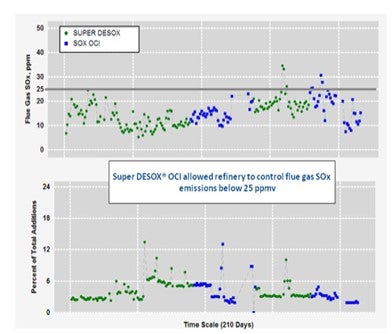
Below is an example of a refiner that historically utilized Super DESOX® and then switched to Super DESOX® OCI. Observed is the ability of Super DESOX® OCI to continue controlling SOx emissions within limits, at comparable dosing rates as was the case with Super DESOX®. Utilizing Super DESOX® OCI over Super DESOX® can result in a SOx additive cost reduction roughly 35%.
Additionally, Grace Davison’s laboratory scale research indicates that the partial burn environment performance of Super DESOX® OCI and Super DESOX® MCD is similar to that of Super DESOX®. Please contact your local Grace Davison sales and technical service representative for additional insight specific to your application.
Year
2011
Process
Question 97: Disposal of catalyst fines from the slurry tank is expensive since they are handled as a hazardous waste. Do you have a way to reinject these tank fines back into the FCC where it would recover? What are other disposal options for these oil laden fines?
Tom Lorsbach (UOP)
I have seen operations at two refineries where FCC slurry tanks were decanted, and the remaining catalyst fines were resuspended with Orbijets and an LCO circulation loop. A slipstream of this LCO slurry was recycled to the riser. In FCC Unit A (~20,000 BPD) the recycled fines partitioned approximately 2/3 to the regenerator side and out with the flue gas and 1/3 partitioned to the reactor side and back out to storage with the main column bottoms product. This refiner successfully used this technique to clean the tank.
The other refinery that attempted this technique for slurry storage tank fines recycle was less successful. The FCC unit in this refinery was larger (70,000 BPD) and the quantity of tank fines for removal was much larger. The effort to recycle LCO slurry was too slow and had to be stopped because the operation could not be completed before the active slurry tank became full. A door sheet was cut in the tank wall and front loaders were used to remove the decanted catalyst fines. These oily catalyst fines were sent to hazardous waste incineration.
Depending on the details of flue gas treating equipment, permits and local environmental regulations, recycling slurry tank fines may or may not be permissible.
Year
2011
Process
Question 98 What measures have you taken to minimize catalyst expenses due to rare earth price inflation? Please include an economic comparison of using a high rare earth catalyst at a lower catalyst addition rate versus using a low rare earth catalyst at a higher catalyst addition rate. Are there alternatives to replace rare earth in FCC catalyst? Are there any negative yield shifts with these new technologies?
Ray Fletcher (Intercat)
Rare earth is an integral component of today's FCC catalyst. Rare earth adds catalyst stability and activity, functions as a vanadium trap and is the oxidizing agent within most SOx additives. Rare earth has also increased in price by over 1500% in the last 18 months. Rare earth has a direct impact on the split between LPG and gasoline in the FCC unit. As rare earth concentration is decreased LPG yield will increase potentially leading to wet gas compressor limitations.
It is suggested that the refiner wishing to minimize catalyst based operating costs consider achieving conversion via operating parameters rather than catalyst activity consistent with unit constraints. These variables include: increasing riser outlet temperature, decreasing feed preheat temperature, recycling an intermediate cut cycle oil or slurry, etc. This strategy is typically more effective during non-summer operations given the fact that most FCC units are limited in main air blower &/or wet gas compressor capacity. An additional strategy for the refiner possessing excess main air blower & catalyst circulation capacity is to consider recycling naphtha or light LCO to the riser. Neither stream will support itself in coke thereby reducing delta coke and increasing catalyst circulation rate for deeper conversion.
Intercat has commercialized a vanadium & nitrogen trap which has in every application resulted in a substantial increase in conversion and also reductions in fresh catalyst additions. This technology enables a refiner to reduce rare earth costs directly via a reduction in rare earth on catalyst concentration at constant conversion or indirectly via a reduction in fresh catalyst addition rate. This additive based technology presents a significant advantage to the refiner in that the effect is cumulative with the improvements made to the catalyst via the catalyst supplier.
The second part of this question is difficult to answer in absolute terms. There are several factors which determine catalyst costs on a daily basis. These include the base catalyst cost which is a function of zeolite content, alumina content, rare earth content plus other factors. Few catalyst suppliers would hold the zeolite content constant while reducing rare earth composition. In order to supply an answer to this question I have assumed that the zeolite-to-matrix ratio remains constant. This implies no changes in zeolite content. Additionally, the required additive injection rate will be primarily a function of the base catalyst intrinsic activity, equilibrium metals concentration and the deactivation rate. As the rare earth concentration on the catalyst decreases the impact of the hydrothermal conditions within the regenerator will result in an increased deactivation rate. The deactivation rate will likely vary between catalyst suppliers.
I have assumed that my typical FCC unit has the following characteristics: charge rate = 41,000 BPD, equilibrium V & Ni = 1500 ppm, target equilibrium activity = 70, fresh catalyst z/m = 3.5, RE/cat: 4.2 - 0. The catalyst cost is assumed to be $3000/ton at zero rare earth. Rare earth costs are estimated assuming variable pricing in $/mTon beginning at $8000 up to $150,000. This data shows that at historical rare earth pricing of two years ago the optimal rare earth concentration (when considering only catalyst costs and not product slate selectivities) was likely greater than 3.0 wt%. At rare earth costs of $100,000 and greater the optimum appears to be less than 1.5 wt%. The last portion of this question addresses new technologies to replace rare earth. We are aware that at least one catalyst supplier is commercializing a new catalyst technology containing a rare earth replacement. We expect that after the panel has provided answers that one or more catalyst supplier representatives will update us with their particular technology. We have reviewed no commercial data defining the stability of this technology and its applicability for heavy oil crackers. We understand that these catalysts have been targeted primarily for VGO operations.
Sudhakar Jale (Grace Davison Refining Technologies)
Grace Davison Refining Technologies has responded quickly to the issues of rare earth price and availability by developing new zero or low rare earth catalysts and additives. Early in 2011, Grace commercialized a family of these catalysts, called REpLaCeR™, for both hydrotreated and resid feed processing. The family of REpLaCeR™ catalysts includes REBEL™, REACTOR™, REMEDY™ and REDUCER™. The REpLaCeR™ family of catalysts utilizes proprietary zeolites and state-of-the-art stabilization methods to deliver performance similar to current rare earth-based FCC technologies. Simply removing the rare earth from a FCC catalyst lowers the Ecat activity significantly. Unit performance will suffer, in most operations, despite higher catalyst circulation rate which results with lower Ecat activity. Catalyst additions of a low rare-earth catalyst must be increased in order to preserve Ecat activity for those units that operate at a catalyst circulation constraint.
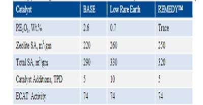
Table 1 summarizes a scenario comparing the base catalyst, base catalyst with low rare earth content and REMEDY™ technology where zeolite is stabilized with proprietary metals. The REMEDY™ technology provides the same activity as the rare earth containing zeolite and hence has the same catalyst additions. Table 1: Simply lowering the RE content will result in increased catalyst additions to hold Ecat activity.
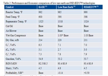
The performance data and the resulting profitability for these three scenarios are summarized in Table 2. Unit constraints for the low rare earth catalyst and REMEDY™ case are air blower, catalyst circulation and wet gas compressor. The low rare earth option where the RE content of base catalyst is lowered is less economically attractive mainly because of higher catalyst additions and the need to reduce conversion due to a wet gas compressor constraint and a catalyst that is more LPG selective. REMEDY™ technology has good activity and selectivity retention vs. the base catalyst thus providing the economic savings of $0.5/B.
The economic advantage of using REMEDY™ catalyst is plotted in Figure 1. The RE2O3 content in low rare earth catalyst is reduced by 75%. This results in a lower catalyst price, but the daily cost increases by about 30% due to higher catalyst additions. REMEDY™ catalyst has 90% lower rare earth as compared to the base case catalyst and maintained same activity and catalyst addition rate as the base case resulting in 30% daily operating cost. A refinery with 50,000 bpd operation increased the profitability by $9 mm/yr (using recent Gulf Coast Economics).
In summary, the REpLaCeR™ family of catalysts introduced by Grace reduces the RE content significantly while maintaining the activity and catalyst additions resulting in a decrease of daily costs by 30%.
Operating at Air Blower and Catalyst Circulation Constraint
Operating at Air Blower, Catalyst Circulation and Wet Gas Compressor Constraint
Profitability includes total catalyst cost
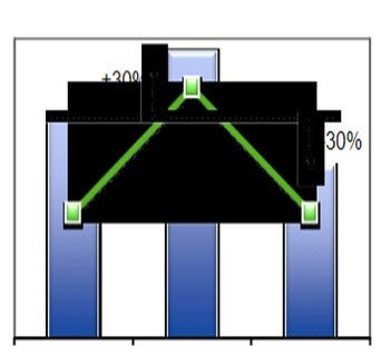
Figure 1: Economics of using REMEDY™ vs. simply reducing the RE content
Year
2011
Process
Question 99: Are there any uncommon FCC metal contaminants showing up on equilibrium catalyst in addition to Ni, V, Fe, Na, and Ca? Are metals traps able to protect the catalyst by selectively capturing Fe, Na, Ca, or any of these uncommon contaminants?
Ray Fletcher (Intercat)
Typical Contaminants
Each of these catalyst poisons may have a significant impact on the FCC catalyst circulating inventory depending upon their concentration. Vanadium will form vanadic acid resulting in the sintering of the zeolite crystal thereby reducing activity. Nickel increases hydrogen yield potentially leading to wet gas compressor constraints and increases delta coke leading to main air blower &/or regenerator temperature constraints. Both iron and calcium deposit on the surface of the catalyst particle leading to possible pore blockage and loss of bottoms conversion. At higher concentrations iron will form nodules on the surface of the catalyst particle and reduce particle density. Calcium is observed to pass through a "cliff" in which the unit conversion is a observed to drop precipitously while the measured activity drops to a much lower degree. Sodium is a permanent poison neutralizing catalyst acid sites thereby resulting in lost activity.
The classic solution to most of these issues has been to dilute the metals using purchased equilibrium catalyst thereby minimizing their effect. Each catalyst and of course your favorite additive supplier has vanadium traps for absorbing excess vanadium. Each catalyst supplier is capable of incorporating crystalline alumina for the encapsulation of nickel thereby reducing its effect on selectivity's. Antimony is well established for passivation of nickel, but the benefits are reduced when good quality crystalline alumina systems are in place. The FCC process engineer is advised to closely monitor crude unit desalter operations for maximum sodium removal. Care is also advised in receiving purchased FCC feedstocks transported cross the oceans for sea water contamination.
Intercat has recently been asked to help deal with the consequences of processing a feed contaminated with molybdenum. The source of contamination was never made clear, but it is believed that it was related to treatments being made to an upstream FCC feed hydrotreater. In this case, Cat Aid was found to be very effective at dealing with the negative side effects from this feed which included hydrogen, dry gas and coke. Hydrogen was reduced by 50% while dry gas dropped by 15%. Coke yield was improved by 6% relative. The bottoms-to-coke ratio also showed a strong improvement.
Nitrogen
Cat-Aid has also been successful particularly in the trapping of nitrogen. Refiners utilizing this technology have in every instance observed an increase in conversion together with the capability of reducing fresh catalyst additions. Typical catalyst addition rate reductions range from 15% to 50% at constant conversion. In each of these operations the activity of the circulating inventory dropped as expected. Fortunately, FCC units are run for conversion and not for activity. Each application has been considered a success. Additionally, many of these units have been able to extend the feed slate to heavier more contaminated feeds thus improving both unit flexibility & profitability.
Mercury
Mercury has been observed in some FCC units. Mercury is present in some, not all, crudes. It is reported that a "belt" of mercury appears to be associated with the boundaries between existing or ancient tectonic plates. In particular, it is reported that the largest mercury deposits in the world are located above areas in which plate subduction has occurred in combination with a degree of volcanic activity. Therefore, mercury most commonly occurs in crude oil that is derived from walls which are located at or near current or historically active plate boundaries. When present the mercury is typically present at ppb levels - perhaps several hundreds of ppb in some cases. Mercury is present in different forms, metal, organomercury compounds, inorganic mercury compounds.
Mercury is toxic metal with a relatively high vapor pressure. Because of its high density and tendency to agglomerate and "bead" it can also be concentrated in drains and other low points of process plants. The potential exists for workers to be exposed to mercury upon opening or cutting any mercury containing pipe work. Hot work would be especially dangerous in this regard. Mercury has a tendency to contact and interact with steel surfaces of pipe work and other equipment and has been found at concentrations up to 10 g/m².
Mercury compounds within crude oil can be characterized into four broad classes including: hydrocarbon soluble, water-soluble, asphaltenes and sediments. Volatile hydrocarbon soluble mercury species tend to track through the refinery with the very lightest hydrocarbon product streams. It is therefore expected that most of these species will be found in and around the streams issuing from the top of the atmospheric column. However, some mercury will boil within the VGO and residue cuts and therefore may be found within FCC units.
One particular refiner found pools of mercury in the FCC flue gas line during a shutdown! This led to multiple employee lawsuits. So it can get clearly get into the FCC. Johnson Matthey has developed a range of mercury traps entitled, PURASPEC, which are able to capture mercury species. Refiners observing mercury within their units are recommended to consider this technology.
Iron
While not a new contaminant, we have observed some interesting and unexpected side effects from high levels of iron contamination recently. It has been observed in several FCC units that as iron concentration on the equilibrium catalyst increases the uncontrolled SO2 emissions also increase. The half-life of this iron appears to be very short on the order of approximately 2 days. These increased emissions can be controlled by utilizing a SOx reducing additive, but large amounts are required as iron is very effective at increasing Sox emissions.
Rosann Schiller and Sudhakar Jale
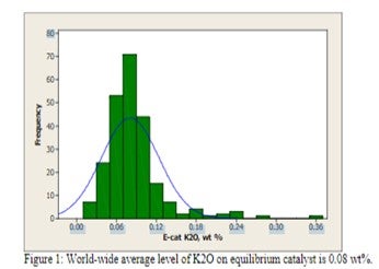
(Grace Davison Refining Technologies) Appearance of an unconventional metal on your equilibrium report can be cause for alarm, but not all metals require action on the part of the refiner. Alkali metals such as sodium and potassium are naturally occurring in crude oil and their concentration is reduced by desalting processes. However, desalter upsets can cause carry over into the FCC feedstock and result in deactivation of the FCC catalyst, particularly under the oxidizing, high temperature conditions in the regenerator. Use of alkali metal contaminated water or steam around an FCC unit can also contribute added contaminants to the catalyst. Alkali metals cause a loss in activity due to neutralization of acid sites. The result is a loss of unit conversion, but not a change in selectivity as observed with iron, nickel, vanadium, or calcium. Flushing of the metal out of the inventory with additional catalyst additions will restore catalytic activity. Typically, only low levels of potassium oxide are observed in equilibrium catalyst [Figure 1].
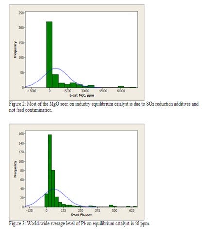
Magnesium is not of concern at low levels (<0.5 wt%), but at higher levels, it has a tendency to react with silica from the zeolite to form forsterite (Mg2SIO4), which will decrease zeolite stability and adversely affect unit conversion. Most of the MgO observed in equilibrium catalyst is due to the presence of SOx reducing additives and not feed contamination [Figure 2].
Lead is well known to cause the deactivation of combustion promoter. However in large enough concentrations on Ecat, Pb can also cause a loss in catalyst activity and conversion. Historical data reports a loss of as much as 1% conversion per 0.1 wt% Pb on Ecat. However, there are no units operating at these levels of Pb in the industry today [Figure 3].
Crude can contain significant calcium naphthenate that may not be removed by conventional desalting and will find its way to the FCC. Calcium poisoning of the FCC unit can be a serious problem, reducing bottoms cracking and catalyst activity. The severity of the impact of calcium on FCC selectivities depends mainly on the amount of incremental calcium that is deposited on the catalyst and the rate of deposition. When the incremental calcium lays down on the FCC catalyst rapidly, the apparent effects of calcium on the unit performance can be more pronounced because there is less time for the unit operator to realize what is happening, identify the root cause of the problem, and take corrective actions. Very few FCC’s operate at high levels of CaO on equilibrium catalyst [Figure 4]; however, poisoning can be evident even at lower levels of contaminant if deposition occurs rapidly.
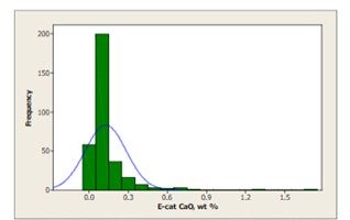
Figure 4: Less than 10 FCC's operate at levels of CaO over 0.75 wt%. The world-wide average level of CaO on equilibrium catalyst is 0.13 wt%, however, CaO poisoning can be evident even at low levels if deposition occurs rapidly.
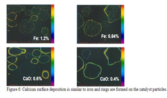
The mechanism by which calcium deactivates FCC catalyst is similar to that of iron deactivation (Yaluris et al, NPRA 2001). The distribution of Fe levels on Ecat is shown in Figure 5. Both metals poison the catalyst by depositing on the exterior surface and over time, will build up on the surface of the catalyst forming rings typically 1-5 μm thick. As the rings form [Figure 6], Fe, and Ca combine with silica, sodium and other contaminants to form low melting temperature phases, which collapse the pore structure of the exterior surface, blocking feed molecules from entering the catalyst particle and reducing conversion. The diffusion of the large molecules inside the particle is the first to be affected by this phenomenon, therefore, the ability of the catalyst to crack bottoms decreases first with a corresponding decrease in cracking activity following.
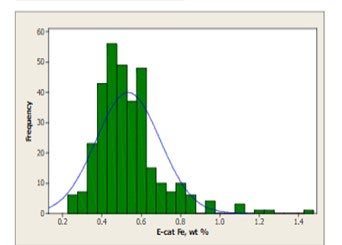
Figure 5: World-wide average level of Fe on equilibrium catalyst is 0.5wt%. The contribution from catalyst is included in this distribution. Approximately 10% of the refiners sampled operate at levels regarded as high.
As the calcium or iron builds up on the catalyst surface and the exterior surface of the particle becomes compromised, the coke selectivity of the catalyst declines due to increased mass transfer limitations, which increase residence time of cracked products inside the catalytic particle and result in higher rates of secondary reactions such as coke. The combination of the loss of coke selectivity, combined with the loss of activity, results in further loss of in-unit conversion.
Figure 7 demonstrates the impact on conversion due to calcium poisoning from a refiner who experienced a doubling of CaO on Ecat in a short period of time due to a change in both crude source and desalter operation. Other contaminants such as sodium also increased in the same time period. In this example, laboratory ACE testing of Ecat demonstrates that the incremental calcium caused a loss of approximately 5 wt% conversion.
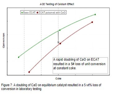
The refiner first observed an increase in bottoms and LCO yields on the unit along with a loss in coke selectivity. Increased catalyst additions were used to flush out contaminated particles and catalyst formulation was optimized to better handle future metals excursions.
Since Fe and Ca are not mobile species in the FCC unit regenerator, the usual trapping technologies, especially those based on separate additive particles are not effective for preventing cracking catalyst poisoning by Fe or Ca.
Several catalytic approaches are recommended to manage calcium issues. Optimization of the pore structure eliminates diffusion limitations. Maximization of the catalyst pore volume in the 100-600 Å range is the best for conversion of bottoms without compromising coke selectivity. Improving coke selectivity of the catalyst will improve performance by offsetting the increased coke make caused by contaminant calcium. High alumina catalysts, especially catalysts with alumina-based binder and matrices, are best suited for operations where high Fe or Ca feeds are commonly processed because they are more resistant to the formation of low melting temperature phases that can destroy the surface pore structure.
In summary, if the increase in contaminant level is temporary, an increase in fresh catalyst addition rate will improve the performance of the catalyst. If high metals feeds will remain a component of the FCC feed, the refiner should minimize the amount of deposition on the Ecat and utilize a catalyst system appropriately designed to handle the potential surface destruction. Such catalyst should contain the appropriate amount of pores in the optimum size of 100-600 Å to overcome diffusion limits. High alumina catalysts such as Grace Davison’s MIDAS® catalyst technology are ideally suited for such applications.
Year
2011
Process
Question 100: What conditions or contaminants will deactivate ZSM-5 additive? What is the half-life of ZSM-5 in clean feed operation? Will contaminants such as vanadium, sodium or other metals adversely affect the propylene selectivity of ZSM-5? What is the best way to monitor the effectiveness of the ZSM-5?
Ray Fletcher (Intercat)
The deactivation mechanism for FCC catalyst is primarily related to unit cell size reduction, and eventually, collapse or sintering of the zeolite crystal. The mechanism of ZSM-5 deactivation is quite different. The deactivation mechanism is simply the dealumination of the ZSM-5 crystal and activity is lost through the loss of active aluminum sites. The crystal structure does not collapse. The activity retention and half-life of the ZSM-5 additive in the circulating inventory is strongly affected by hydrothermal conditions within the regenerator with temperature being the dominant variable.
ZSM-5 additive activity is less affected by contaminant metals than FCC catalyst. This is due to the fact that heavy feed molecules containing contaminant metals such as vanadium are less likely to crack on ZSM-5. ZSM-5 will therefore maintain its activity longer than FCC catalyst. It is worth pointing out that a unit experiencing high equilibrium vanadium levels will likely experience a loss in conversion which reduces LPG yields. This may give the appearance of a ZSM-5 effect. The propylene selectivity will likely remain unaffected.
The activity retention difference between ZSM-5 and FCC catalyst will increase as the equilibrium metals level increases. Intercat has evaluated ZSM-5 additive half-lives for several units and has found a typical half-life of approximately 18 days with a minimum of two days and a maximum of 36 days. ZSM-5 additive activity in an operating unit is strongly affected by the catalyst replacement rate. Units having a very high replacement rate present a higher average ZSM-5 activity then units with very low change out rate.
A paper presented at the 2000 ACS conference investigated the subject of LPG selectivity differences in detail. This study reviewed additives having different ZSM-5 crystal content, different levels of additive additions in the FCC, additives from different manufacturers, additives with different silica-to-alumina ratios and additives steamed at different severities. The results of the study can be plotted on one chart (include chart).
This data demonstrates that if one additive were more selective than another the propylene yield would fall on a different line which did not occur. All additives tested at all concentrations fall on the same line. We also see that the propylene yield increases faster than butylene yield and that higher delta LPG yield leads to higher propylene yields. Additive zeolite content, type, method of manufacture, and steaming severity has no effect on the selectivity of the final LPG product. The ratio of propylene to butylene in the final product depends only on how much LPG is made. The conclusion is that ZSM-5 additive selectivity is determined by the zeolite structure alone. Therefore, measuring activity differences is more important than looking for selectivity differences with standard ZSM-5 additive. (Please note that these results apply only to standard ZSM-5 technology.)
While propylene selectivity's are determined by the ZSM-5 crystal structure, the activity and stability of the various additives are determined by the crystal stabilization technology employed plus the interaction of the crystal with the matrix. An additive containing properly stabilized ZSM-5 crystal combined with a strong matrix will result in excellent activity retention with superior propylene yields when compared to other technologies. Intercat, and other suppliers, has invested significantly in the development of ZSM-5 additive technology. This is reflected in our broad product portfolio. Intercat possesses a broad range of ZSM-5 additives maximizing propylene, butylene and octanes. Additionally, Intercat produces ZSM-5 additives which minimize LPG increase for wet gas compressor limited operations.
There are several selectivity-based ratios which can be used in monitoring ZSM-5 performance.
These include: propane olefinicity, propylene yield vs. LPG, propylene vs. conversion, propylene vs. butylene and propylene vs. gasoline. The most important of these ratios are the propane olefinicity and the propylene-to-LPG ratio.
Matthew Meyers (Western Refining)
In VGO operation with less than 0.5 ppm vanadium, the half-life was observed to be roughly 18 days. For use in an LP model or to ensure that the alkylation unit remains optimized at varying feed rates, monitor the C3= and C4= yield shifts relative to FCC feed rate. A typical vector during z additive usage might be +3 for C3= vol% of feed and +2 for C4= vol% of feed, depending on the z additive dosage rate.
Kristen Wagner (Grace Davison Refining Technologies)
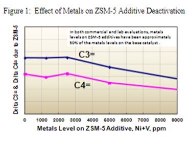
ZSM-5 based additives maintain their activity in high metals applications because they deactivate at a much lower rate than their Y-zeolite base catalyst counterparts. Grace has extensive R&D and commercial experience with ZSM-5 containing additives used in FCC units, including those that are designed for maximum propylene yield. These commercial FCC operations vary in feed metals levels, feed type, unit design and operating conditions. When analyzing commercial Ecat for ZSM-5 additive performance, it has been observed that feed metals will preferentially adhere to the base catalyst versus the ZSM-5 additive. Separation of equilibrium catalyst into its base catalyst and ZSM-5 additive components shows the ZSM-5 additive typically only contains about half the metals of the FCC base catalyst. In laboratory deactivation studies by Grace, ZSM-5 additives begin to deactivate at Ni+V loadings of 3000 ppm and greater, as seen in Figure 1 below. However, based on our current commercial experience, a ZSM-5 additive sample containing 3000 ppm Ni+V, would likely require approximately 6000 ppm Ni+V on the circulating base catalyst.
ZSM-5 additives are very stable and maintain activity much longer than other FCC catalysts or additives. The specific half-life of a ZSM-5 additive will vary from unit to unit but could easily range from two weeks to significantly longer, depending on the FCC operation. In Grace’s experience, the half-life of a ZSM-5 additive strongly depends on the operating conditions of the unit and not as much on the feed type or metals levels. Variables which will impact the half-life of a ZSM-5 additive include, regenerator temperature, unit pressure, and circulation rate, which influences the number of cracking cycles the additive undergoes in the unit each day. We have commercially observed higher than typical ZSM-5 deactivation rates in units running clean feeds but operating at higher pressure, higher circulation rates and higher regenerator temperatures.
ZSM-5 based additives are more resistant to sodium and potassium promoted zeolite destruction than Y-zeolite. Vanadium will likely have the greatest effect on ZSM-5 deactivation, however all contaminants in the FCC will have a much stronger effect on base catalyst deactivation, before they will adversely impact the ZSM-5 activity. Grace has not experienced any shifts in propylene selectivity due to contaminant levels or deactivation of ZSM-5 however more research is needed on this subject to provide a definitive answer.
For evaluating the effectiveness of ZSM-5 additives in a commercial unit, a common approach is to monitor propylene and butylene yields as a function of corrected conversion. ZSM-5 additives will increase LPG olefins for each given level of conversion. Another recommended method to measure the effectiveness of ZSM-5 additives is to analyze the increase in gasoline octane by evaluating gasoline octane as a function of reactor outlet temperature.
Grace has also been successful in evaluating ZSM-5 based additive performance using a multivariable regression approach. By utilizing a statistical tool such as Minitab, the LPG olefin or gasoline octane shifts can be quantified as a function of feed properties, operating conditions and ZSM-5 concentration.
Laboratory options also exist for measuring ZSM-5 additive effectiveness in the unit. In a controlled laboratory setting, performance comparisons can be made by taking a ZSM-5 containing equilibrium catalyst sample and a non-ZSM-5 containing equilibrium catalyst sample and analyzing them in an ACE unit or riser pilot plant, using a constant feedstock. This method is beneficial for analyzing ZSM-5 performance in commercial units that have experienced large changes in feed or operating conditions, which make ZSM-5 additive performance evaluations more challenging.
In summary, ZSM-5 based additives have excellent activity and stability even in high metals applications. Grace ZSM-5 additives have been shown to perform well with all types of FCC catalysts and FCC feedstocks and under a wide range of operating conditions and unit designs. Grace manufactured ZSM-5 additives are currently in use in over 70 FCC units worldwide and in more than half of the FCC propylene maximization operations in EMEA and Asia.
Year
2011
Process
Question 101: What analytical methods can distinguish between organic and inorganic iron (Fe) compounds in the feed? What type of iron, organic or inorganic, affects catalyst performance? Considering the relatively long reaction residence time of most laboratory test units used to measure activity, will activity testing properly reflect the actual in-FCCU activity under conditions of Fe contamination? What is your best method to monitor the catalyst performance under Fe contamination? Is ther
Dwight Agnello-Dean (BP)
We have not routinely attempted to identify the organic and inorganic iron components in our feeds. An internal expert suggested two approaches. First to determine the organic iron using ICP-OES, then wash the same sample with DI water, or slightly acidified water, and utilizing atomic absorption, determine the inorganic iron. The second approach is to determine total iron utilizing X-Ray, ICP or Atomic Absorption. Following this step remove the solids and water soluble, which would contain the inorganic iron, and rerun the hydrocarbon sample to determine the organic iron. The difference between total iron and organic iron is the inorganic iron.
As far as which form of iron affects catalyst performance, we follow the general consensus that organic iron is the issue and of primary interest. Over the last decade we have experienced catalyst performance issues that were correlated with elevated iron on the catalyst. During these events, ecat testing did not indicate an appropriate drop-in catalyst activity, which supports the questioner’s point that ecat program test methods are not adequate for this purpose. The symptoms we do look for are loss in bottoms upgrading (higher DCO yields), a drop in catalyst bulk density (ABD), a change in fluidization properties, potential circulation issues, and of course elevated iron on ecat. Across our units we don’t have a single critical iron level where we would expect problems because we consider this to be impacted by both the catalyst and the feedstock. Therefore, our current practices are to monitor our normal iron on ecat level and begin looking for other symptoms if we see the iron increase 0.3 wt.% over normal. For the units I am most closely associated with I expect to stay below 0.8 wt% iron. These units process very clean VGO feeds.
Ray Fletcher (Intercat)
Testing methods for feed stock analyses may be found in ASTM D7691 - 11 which include standard test methods for multi-element analysis of crude oils using inductively coupled plasma atomic emission spectrometry (ICP-AES). We believe that the high-performance liquid chromatography ICP-AES may be better at distinguishing organic and inorganic metal species.
It is widely accepted that organic iron in porphyries and naphthenates negatively affect the catalytic performance more than does inorganic iron.
The primary reason for the different performance effects between organic and inorganic iron is related to the size of these molecules. It is believed that small inorganic iron species are able to penetrate into the catalyst particle in most cases and disperse easily. On the other hand, large organic iron bearing molecules are typically sterically hindered and thus are unable to penetrate within the FCC catalyst particle. These molecules tend to deposit on the particle surface forming a barrier to diffusion. These iron rich layers are often several microns thick having a very rough nodular structure.
Our R&D team has found that the ECAT surface contaminated by organic iron contains a very dense amorphous iron rich layer which seals the macro, meso and micro-pores of catalyst. There is no penetration and reaction found at the interface between the iron layer and catalyst. The outer surface of an iron poisoned catalyst particle consists of a dense amorphous aluminosilicate phase with polycrystalline magnetite (Fe3O4) nanoparticles on top.
Most laboratory deactivation and testing methodologies used today are unable to accurately predict the effect of iron poisoning in a commercial unit. FCC catalyst suppliers have been active in developing special deactivation conditions to enable more accurate prediction capability with iron poisoning. None of these deactivation procedures have yet been able to accurately model an iron contaminated unit. The one test unit which may be capable of distinguishing iron effects is the circulating pilot plant. However, due to the sample sizes involved and the time & cost commitments few refiners have been willing to carry out extensive testing with this equipment.
The best method for monitoring iron poisoning is systematic and detailed unit monitoring. The focus is on "add-on iron". Most FCC catalysts contain 0.2-0.4 wt% iron depending upon the kaolin content and source. The add-on iron is the equilibrium iron less the fresh iron. Most catalyst systems are capable of handling +0.3 wt% add-on iron before negative effects are observed. Catalysts with alumina-based binding systems are usually capable of absorbing higher levels of iron at approximately 0.4-0.5 wt%.
The actual amount of iron the equilibrium catalyst is capable of absorbing without negative impact is directly related to the concentration of all contaminant metals including: nickel, vanadium, sodium, calcium plus iron. Most catalyst systems begin to observe negative effects when the total metal levels exceed 13,000 to 15,000 ppm. There are a few FCC units which regularly defy this rule of thumb having iron levels exceeding one wt%. These units are believed to be exceptions rather than the rule.
Iron nodules have been observed on the surface of equilibrium catalysts which have undergone high levels of iron contamination. The net result of these nodules has been poor blockage with a corresponding loss in bottoms conversion plus an apparent drop in ABD due to altered packing efficiencies. Many times, in spite of a lower ABD the fluidization characteristics of the unit have deteriorated. Additionally, as stated in question #99, step change increases in iron have been observed to precipitate that changes in SOx emissions. These step change increases in emissions are easily controlled by SOx reducing additive.
It is recommended that the process engineer monitor closely the levels of add-on iron and total contaminant metals. Both of these variables may be plotted against bottoms conversion or conversion. The refiner may then draw their own conclusion regarding maximum allowable iron contamination. Three methodologies exist for combating iron excursions include: 1) flush catalyst, 2) higher fresh catalyst additions &/or 3) reformulation to a more iron tolerance catalyst system.
Finally, Intercat would like to propose an alternative explanation to the underlying mechanism leading to nodule formation in iron contaminated units. It has been observed that the composition of these nodules is not solely iron but is enriched with silica. Interestingly, one would expect that beneath the iron nodules there would be silica depleted regions within the catalyst particle. However, this is not the case. The composition of the catalyst directly beneath the iron nodule has equivalent silica concentrations as those regions not affected by these nodules. This leads us to hypothesize that iron acts as a nucleating site for silica/iron nodule formation. As stated earlier, these nodules have multiple negative impacts such as reduction in conversion, reduction in ABD, and occasionally, deterioration in fluidization characteristics. (Our thanks to Dr. Diddams for sharing this hypothesis with us.)
Ann Benoit (Grace Davison Refining Technologies)
Yaluris discussed that there are two types of iron. One type is particles of inorganic iron from hardware and is usually considered benign in FCC unit performance. The second type is organic based Fe potentially coming in with the feed and/or from hardware corrosion by naphthenic acids and other corrosive feed components. This type of iron can negatively impact unit performance. (1) ACE testing is a better technique to measure the conversion impact of organic based iron contaminated catalyst, compared to traditional fixed bed MAT testing. However, ACE testing should be used together with other tests to confirm iron poisoning.
Below are several methods that can be used to monitor catalyst performance under Fe contamination:
•Ecat analysis (Fe, Na, CaO, ABD, color)
•Scanning Electron Microscope imaging (SEM)
•Optical microscope
•Ecat diffusivity
A decline in unit performance such as, reduction in bottoms conversion, and/or poor catalyst circulation coupled with an increase in equilibrium catalyst Fe levels can indicate Fe poisoning. Yaluris discussed how pore closure and nodule formation can be potentially caused by iron contamination (1). Pore closure can negatively affect bottoms conversion in the unit. An excellent way to show the actual nodules is by Scanning Electron Microscope imaging (SEM). It is important to note that some nodules may not be a problem, but there is a problem when the nodules become obviously raised from the surface and all over the catalyst particle. A drop in ABD (apparent bulk density) on Ecat can indicate nodules formation due to iron poisoning as Ecat does not pack as densely. The ABD change, pore plugging and the potential for particles to stick together can negatively impact unit catalyst circulation.
Optical microscope is another method to indicate iron poisoning. Ecat samples with iron poisoning will show glassy reflections under an optical microscope with illumination. (1) The color of Ecat could potentially indicate high levels of Fe. Ecat samples can have a reddish brown tint when poisoned by iron.(1) In addition to Ecat Fe levels, Na and CaO should be monitored as well. Fe in the presence of Na and/or CaO can act as a fluxing agent which can aggravate the effects of Fe.(1)
Year
2011
Process
